Table of Contents
Advertisement
Quick Links
Catalyst 6800IA Switch Hardware Installation Guide
First Published: 2013-09-23
Last Modified: 2014-07-28
Americas Headquarters
Cisco Systems, Inc.
170 West Tasman Drive
San Jose, CA 95134-1706
USA
http://www.cisco.com
Tel: 408 526-4000
800 553-NETS (6387)
Fax: 408 527-0883
Text Part Number: OL-30278-02
Advertisement
Table of Contents

Related Manuals for Cisco Catalyst 6800IA


Summary of Contents for Cisco Catalyst 6800IA
- Page 1 Catalyst 6800IA Switch Hardware Installation Guide First Published: 2013-09-23 Last Modified: 2014-07-28 Americas Headquarters Cisco Systems, Inc. 170 West Tasman Drive San Jose, CA 95134-1706 http://www.cisco.com Tel: 408 526-4000 800 553-NETS (6387) Fax: 408 527-0883 Text Part Number: OL-30278-02...
- Page 2 Cisco and the Cisco logo are trademarks or registered trademarks of Cisco and/or its affiliates in the U.S. and other countries. To view a list of Cisco trademarks, go to this URL: www.cisco.com/go/trademarks . Third-party trademarks mentioned are the property of their respective owners. The use of the word partner does not imply a partnership relationship between Cisco and any other company.
-
Page 3: Table Of Contents
Port LEDs and Modes STACK LED Console LEDs Ethernet Management Port LED Rear Panel FlexStack-Plus Ports and LEDs RPS Connector Cisco RPS 2300 AC Power Connector Power Supply Modules (Applies to the Catalyst 6800IA-48FPDR Switches) Catalyst 6800IA Switch Hardware Installation Guide OL-30278-02... - Page 4 Removing an SFP Module Connecting to SFP and SFP+ Modules Connecting to Fiber-Optic SFP and SFP+ Modules Connecting to 1000BASE-T SFP 10/100/1000 PoE and PoE+Port Connections 10/100/1000 Port Connections Auto-MDIX Connections Where to Go Next Catalyst 6800IA Switch Hardware Installation Guide OL-30278-02...
- Page 5 Finding the Serial Number Technical Specifications A P P E N D I X A Environmental Specifications Specifications for the Catalyst 6800IA Switches Connector and Cable Specifications A P P E N D I X B Connector Specifications 10/100/1000 Ports (Including PoE)
- Page 6 Contents Cables and Adapters SFP Module Cables Cable Pinouts Console Port Adapter Pinouts Catalyst 6800IA Switch Hardware Installation Guide OL-30278-02...
-
Page 7: Preface
A vertical line, called a pipe, indicates a choice within a set of keywords or arguments. [x | y] Optional alternative keywords are grouped in brackets and separated by vertical bars. Catalyst 6800IA Switch Hardware Installation Guide OL-30278-02... - Page 8 Use the statement number provided at the end of each warning to locate its translation in the translated safety warnings that accompanied this device. Statement 1071 SAVE THESE INSTRUCTIONS Catalyst 6800IA Switch Hardware Installation Guide viii OL-30278-02...
-
Page 9: Related Documentation
Obtaining Documentation and Submitting a Service Request For information on obtaining documentation, submitting a service request, and gathering additional information, see the monthly What's New in Cisco Product Documentation, which also lists all new and revised Cisco technical documentation, at: http://www.cisco.com/c/en/us/td/docs/general/whatsnew/whatsnew.html... - Page 10 Preface Obtaining Documentation and Submitting a Service Request Catalyst 6800IA Switch Hardware Installation Guide OL-30278-02...
-
Page 11: Product Overview
C H A P T E R Product Overview The Catalyst 6800IA switches are Ethernet switches to which you can connect devices such as Cisco IP Phones, Cisco Wireless Access Points, workstations, and other network devices such as servers, routers, and other switches. -
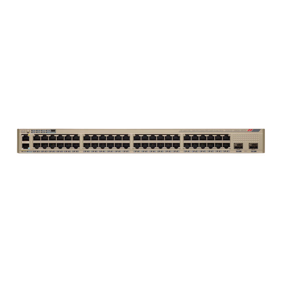
Page 12: Front Panel
• Ethernet management port • RJ-45 console port • LEDs • Mode button The Catalyst 6800IA-48FPD switch is shown here as an example. Other switches have similar components. Figure 1: Catalyst 6800IA-48FPD Front Panel Mode button and switch LEDs 10/100/1000 PoE+ ports... -
Page 13: Poe And Poe+ Ports
The ports provide PoE+ support for devices compliant with IEEE 802.3af, IEEE 802.3at, and ePoE and also provide Cisco prestandard PoE support for Cisco IP Phones and Cisco Aironet Access Points. The maximum switch power output is 740 W. Intelligent power management allows flexible power allocation across all ports. -
Page 14: Sfp+ Module Slots
SFP+ Module Slots If you use the USB mini-Type B console port, the Cisco Windows USB device driver must be installed on any PC connected to the console port (for operation with Microsoft Windows). Mac OS X or Linux do not require special drivers. -
Page 15: Catalyst 6800Ia Switch Hardware Installation Guide
Product Overview LEDs This figure shows the switch LEDs and the Mode button that you use to select a port mode. Figure 3: Switch LEDs and Mode Button for the Catalyst 6800IA Switches or IRPS STACK LED SPEED LED PoE LED... -
Page 16: System Led
System is receiving power but is not functioning properly. Blinking amber System is sleep mode. RPS LED The RPS LED is only available on switch models that have an RPS port (Catalyst 6800IA-48FPD and 6800IA-48TD switches). Table 3: RPS LED Color RPS Status RPS is off or not properly connected. -
Page 17: Master Led
Port speed The port operating speed: 10, 100, 1000 Mb/s, or 10 Gb/s. STACK Stack member status The stack member status. Stack port status The stack port status. PoE port power The PoE status. Catalyst 6800IA Switch Hardware Installation Guide OL-30278-02... -
Page 18: Catalyst 6800Ia Switch Hardware Installation Guide
PoE is off due to a fault. Noncompliant cabling or powered devices can cause a PoE port fault. Use only standard-compliant cabling to connect Cisco prestandard IP Phones and wireless access points or IEEE 802.3af-compliant devices. You must remove any cable or device that causes a PoE fault. -
Page 19: Stack Led
Express Setup mode. To disable Express Setup, Contact Cisco TAC. Even if PoE mode is not selected, this LED still shows PoE problems if they are detected. -
Page 20: Console Leds
RJ-45 console port Green RJ-45 console port is active. When this LED is on, the USB console port LED is off. The port is not active, and the USB console port is active. Catalyst 6800IA Switch Hardware Installation Guide OL-30278-02... -
Page 21: Ethernet Management Port Led
Amber POST failure. Rear Panel The rear panel of the Catalyst 6800IA-48FPD and 6800IA-48TD switches have FlexStack-Plus ports, a fan exhaust, an RPS connector, and an AC power connector. Figure 5: Catalyst 6800IA Switch Rear Panel Catalyst 6800IA Switch Hardware Installation Guide... -
Page 22: Catalyst 6800Ia Switch Hardware Installation Guide
Rear Panel FlexStack-Plus ports RPS Connector Fan Exhaust AC power connector The rear panel of the Catalyst 6800IA-48FPDR switches have FlexStack-Plus ports and power supply module slots. Figure 6: Catalyst 6800IA Switch Rear Panel FlexStack-Plus ports PS OK LED Power supply slot (with blank module) -
Page 23: Flexstack-Plus Ports And Leds
Product Overview FlexStack-Plus Ports and LEDs FlexStack-Plus Ports and LEDs The Catalyst 6800IA switches support stacking with the FlexStack-Plus ports on the switch rear panel and a 0.5-meter FlexStack cable. Figure 7: FlexStack-Plus Ports LED for Stack port 1 LED for Stack port 2... -
Page 24: Cisco Rps 2300
The Cisco RPS 2300 has two output levels: –52 V and 12 V with a total maximum output power of 2300 W. All supported and connected switches can simultaneously communicate with the RPS 2300. You can configure these RPS 2300 features through the switch software: •... -
Page 25: Catalyst 6800Ia Switch Hardware Installation Guide
Product Overview Power Supply Modules (Applies to the Catalyst 6800IA-48FPDR Switches) The 1025-W power supply module is an autoranging unit that supports input voltages between 115 and 240 VAC. All power supply modules have internal fans. All switches ship with a blank cover in the second power supply slot. -
Page 26: Catalyst 6800Ia Switch Hardware Installation Guide
Product Overview Power Supply Modules (Applies to the Catalyst 6800IA-48FPDR Switches) Catalyst 6800IA Switch Hardware Installation Guide OL-30278-02... -
Page 27: Switch Installation
This section includes the basic installation caution and warning statements. Read this section before you start the installation procedure. Translations of the warning statements appear in the RCSI guide on Cisco.com. Before working on equipment that is connected to power lines, remove jewelry (including rings, necklaces, Warning and watches). - Page 28 Statement 378 Warning Attach only the following Cisco external power system to the switch: PWR-RPS2300 Statement 387 Warning Do not work on the system or connect or disconnect cables during periods of lightning activity. Statement...
- Page 29 Use the statement number provided at the end of each warning to locate its translation in the translated safety warnings that accompanied this device. Statement 1071 Catalyst 6800IA Switch Hardware Installation Guide OL-30278-02...
-
Page 30: Tools And Equipment
• Airflow around the switch and through the vents is unrestricted. • Temperature around the unit does not exceed 113°F (45°C). If the switch is installed in a closed or multirack assembly, the temperature around it might be greater than normal room temperature. Catalyst 6800IA Switch Hardware Installation Guide OL-30278-02... -
Page 31: Verifying Switch Operation
When you connect the RPS to the switch, put the RPS in standby mode. Set the RPS to active mode during Note normal operation. Attach only the following Cisco external power system to the switch: Cisco XPS 2200 Statement 387 Warning Planning and Installing a Switch Stack (Optional) Stack Guidelines •... -
Page 32: Stack Cabling
Stacking using FlexStack-Plus Modules These figures show the switches stacked in a vertical rack or on a table. The connections are redundant.A Catalyst 6800IA-48FPD switch is shown in the examples, the Catalyst 6800IA-48FPDR switch can be stacked the same way. - Page 33 Using FlexStack-Extended Hybrid module, you can combine existing stack of switches and new switches spread across multiple wiring closets into one single stack. To achieve this, the copper port on the FlexStack-Extended Hybrid module should be connected to the FlexStack-Plus port on a switch in your Catalyst 6800IA Switch Hardware Installation Guide OL-30278-02...
- Page 34 Switch Installation Stack Cabling existing network. The fiber port on the Cisco FlexStack-Extended Fiber module can be used to connect switches over long distances. You can stack up to eight switches. Figure 12: Extending Traditional FlexStack-Plus Stacks using FlexStack-Extended Modules The following image shows a mixed stack network using FlexStack-Plus, FlexStack-Extended Fiber and Hybrid modules.
-
Page 35: Stack Bandwidth And Partitioning Examples
Figure 15: Stack with Half Bandwidth Connections This figure shows a stack with a bad FlexStack cable in link B. This stack provides only half bandwidth and does not have redundant connections. Figure 16: Stack with a Failover Condition Catalyst 6800IA Switch Hardware Installation Guide OL-30278-02... -
Page 36: Power-On Sequence For Switch Stacks
• Power off a switch before you add it to or remove it from an existing switch stack. For conditions that can cause a stack master reelection or to manually elect the stack master, see the Catalyst 2960-X Switch Stacking Configuration Guide on Cisco.com. Installing the Switch Rack-Mounting Installation in other than 19-inch racks requires a bracket kit not included with the switch. - Page 37 • If the rack is provided with stabilizing devices, install the stabilizers before mounting or servicing the unit in the rack. Statement 1006 This figure shows the standard 19-inch brackets and other optional mounting brackets. You can order the optional brackets from your Cisco sales representative. Figure 18: Rack-Mounting Brackets 19-inch brackets 23-inch brackets...
-
Page 38: Attaching The Rack-Mount Brackets
Use two Phillips flat-head screws (for Catalyst 6800IA-48FPD and 6800IA-48TD) or four Phillips flat-head screws (for Catalyst 6800IA-48FPDR) to attach the long side of the bracket to each side of the switch. Figure 19: Attaching Brackets for 19-inch Racks (Catalyst 6800IA-48FPD and 6800IA-48TD) -
Page 39: Mounting In A Rack
Use the four supplied Phillips machine screws to attach the brackets to the rack. Step 2 Use the black Phillips machine screw to attach the cable guide to the left or right bracket. Catalyst 6800IA Switch Hardware Installation Guide OL-30278-02... - Page 40 Switch Installation Rack-Mounting Cable guide Number-12 Phillips pan-head screws (48-0523-01) or Number-10 Phillips pan-head screws (48-0627-01) Phillips machine screw, black (48-0654-01) Mid-mounting position Front-mounting position Rear-mounting position Catalyst 6800IA Switch Hardware Installation Guide OL-30278-02...
-
Page 41: Wall-Mounting
Figure 21: Attaching the 19-inch Brackets for Wall-Mounting Number-8 phillips flat-head screws (48-2927-01) Attaching the RPS Connector Cover If an RPS is not connected to the switch, install an RPS connector cover on the back of the switch. Statement Warning Catalyst 6800IA Switch Hardware Installation Guide OL-30278-02... -
Page 42: Mounting On A Wall
Read the wall-mounting instructions carefully before beginning installation. Failure to use the correct hardware or to follow the correct procedures could result in a hazardous situation to people and damage to the system. Statement 378 Catalyst 6800IA Switch Hardware Installation Guide OL-30278-02... - Page 43 User-supplied screws (for example, you can use # 6 wood screws with a washer head 1-inch long). When you complete the switch installation, see After Switch Installation, on page 34 for information on switch configuration. Catalyst 6800IA Switch Hardware Installation Guide OL-30278-02...
-
Page 44: Installing The Switch On A Table Or Shelf
Always use a Cisco-approved FlexStack cable to connect the switches. Note This is only supported on the stack-capable switches. Use only approved cables, and connect only to other Catalyst 6800IA switches. Equipment might be Caution damaged if connected to other nonapproved Cisco cables or equipment. -
Page 45: Removing A Flexstack Cable
When you remove the FlexStack cables from the connectors, replace the dust covers to protect them from dust. Removing and installing the FlexStack cable can shorten its useful life. Do not remove and insert Caution the cable more often than is absolutely necessary. Catalyst 6800IA Switch Hardware Installation Guide OL-30278-02... -
Page 46: Installing The Power Cord Retainer (Optional)
Installing the Power Cord Retainer (Optional) Installing the Power Cord Retainer (Optional) This section applies only to the Catalyst 6800IA-48FPD and 6800IA-48TD switches. Note The power cord retainer is optional (part number [PWR-CLP=]). You can order it when you order your switch, or you can order it later from your Cisco representative. - Page 47 Latch Smaller sleeve for thin power cords Step 4 Slide the retainer through the other latches to lock it. Figure 26: Locking the Retainer AC power cord Latches Sleeve for thin power cords Catalyst 6800IA Switch Hardware Installation Guide OL-30278-02...
-
Page 48: Installing Sfp Modules
Secure the AC power cord by pressing on the retainer. Figure 28: Securing the Power Cord in the Retainer Installing SFP Modules Installing an SFP or SFP+ Module Before You Begin When installing SFP or SFP+ modules, observe these guidelines: Catalyst 6800IA Switch Hardware Installation Guide OL-30278-02... - Page 49 If the module has a bale-clasp latch, close it. Step 6 For fiber-optic SFP or SFP+ modules, remove the dust plugs and save. Step 7 Connect the SFP cables. Figure 29: Installing an SFP Module Catalyst 6800IA Switch Hardware Installation Guide OL-30278-02...
-
Page 50: Removing An Sfp Module
Insert one end of the fiber-optic cable into the SFP or SFP+ module port. Step 3 Insert the other cable end into a fiber-optic receptacle on a target device. Figure 30: Connecting to a Fiber-Optic SFP Module Port Step 4 Observe the port status LED. Catalyst 6800IA Switch Hardware Installation Guide OL-30278-02... -
Page 51: Connecting To 1000Base-T Sfp
The automatic medium-dependent interface crossover (auto-MDIX) feature is enabled by default. For Note configuration information for this feature, see the switch software configuration guide or the switch command reference on Cisco.com. To prevent ESD damage, follow your normal board and component handling procedures. Caution Catalyst 6800IA Switch Hardware Installation Guide OL-30278-02... - Page 52 • If the LED is off, the other device might not be turned on, there might be a cable problem, or there might be a problem with the adapter in the other device. Step 4 If necessary, reconfigure and restart the switch or other device. Catalyst 6800IA Switch Hardware Installation Guide OL-30278-02...
-
Page 53: 10/100/1000 Poe And Poe+Port Connections
On a per-port basis, you can control whether or not a port automatically provides power when an IP phone or an access point is connected. To access an advanced PoE planning tool, use the Cisco Power Calculator available on Cisco.com at this URL: http://tools.cisco.com/cpc/launch.jsp... -
Page 54: 10/100/1000 Port Connections
5 100BASE-TX and 1000BASE-T traffic requires twisted four-pair, Category 5 or higher. 10BASE-T traffic can use Category 3 cable or higher. Where to Go Next Refer to the "Instant Access" chapter in the Release 15.1SY Supervisor Engine 2T Software Configuration Guide. Catalyst 6800IA Switch Hardware Installation Guide OL-30278-02... -
Page 55: Power Supply Installation
C H A P T E R Power Supply Installation This chapter applies only to the Catalyst 6800IA-48FPDR switch. It contains these topics: • Power Supply Module Overview, page 45 • Installation Guidelines, page 47 • Installing or Replacing an AC Power Supply, page 48 •... - Page 56 PS OK LED Release latch AC power cord retainer Power supply If no power supply is installed in a power supply slot, install a power supply slot cover. Figure 33: Power Supply Slot Cover Catalyst 6800IA Switch Hardware Installation Guide OL-30278-02...
-
Page 57: Installation Guidelines
Do not reach into a vacant slot or chassis while you install or remove a module. Exposed circuitry could Warning constitute an energy hazard. Statement 206 Only trained and qualified personnel should be allowed to install, replace, or service this equipment. Warning Statement 1030 Catalyst 6800IA Switch Hardware Installation Guide OL-30278-02... -
Page 58: Installing Or Replacing An Ac Power Supply
Power Supply Installation Installing or Replacing an AC Power Supply If a Cisco external power system is not connected to the switch, install the provided connector cover on Warning the back of the switch. Statement 386 Installing or Replacing an AC Power Supply... -
Page 59: Finding The Serial Number
Note Finding the Serial Number If you contact Cisco Technical Assistance, you need to know the switch serial number. You can also use the show version privileged EXEC command to see the switch serial number. Figure 36: 1025-W AC Power Supply Serial Number... - Page 60 Power Supply Installation Finding the Serial Number Catalyst 6800IA Switch Hardware Installation Guide OL-30278-02...
-
Page 61: Troubleshooting
You can also get statistics from Device Manager, from the CLI, or from an SNMP workstation. Switch POST Results POST failures are usually fatal. Contact your Cisco technical support representative if your switch does not pass POST. Switch LEDs If you have physical access to the switch, look at the port LEDs for troubleshooting information about the switch. -
Page 62: Ethernet And Fiber-Optic Cables
• Use the Mode button to show the status for all ports. • Use the show interfaces privileged EXEC command to see if the port is error-disabled, disabled, or shutdown. Reenable the port if necessary. Catalyst 6800IA Switch Hardware Installation Guide OL-30278-02... -
Page 63: 10/100/1000 Poe+ Port Connections
SFP and SFP+ Module Use only Cisco SFP or SFP+ modules in the switch. Each Cisco module has an internal serial EEPROM that is encoded with security information. This encoding provides a way for Cisco to identify and validate that the module meets the requirements for the switch. -
Page 64: Ping End Device
To troubleshoot autonegotiation problems, try manually setting both sides of the connection. If this does not solve the problem, there could be a problem with the firmware or software on your NIC. You can resolve this by upgrading the NIC driver to the latest version. Catalyst 6800IA Switch Hardware Installation Guide OL-30278-02... -
Page 65: Cabling Distance
Finding the Serial Number If you contact Cisco Technical Assistance, you need to know the switch serial number. You can also use the show version privileged EXEC command to see the switch serial number. - Page 66 Troubleshooting Finding the Serial Number Catalyst 6800IA Switch Hardware Installation Guide OL-30278-02...
-
Page 67: Technical Specifications
Storage altitude Up to 15,000 ft (4500 m) 6 Minimum ambient temperature for cold start is 32°F (0°C) Table 17: Environmental and Physical Specification for the AC Power Supply for the Catalyst 6800IA-48FPDR Switches Power Requirements Operating temperature 23 to 113°F (–5 to 45°C) –40 to 158°F (–40 to 70°C) -
Page 68: Specifications For The Catalyst 6800Ia Switches
Note supplies. Dimensions (H x D x W) 1.75 x 16.05 x 17.5 in. (4.45 x 40.77 x 44.5 cm) Table 19: Power Specifications for the PWR-C2-1025WAC (Catalyst 6800IA-48FPDR Switches) Power Requirements Maximum output power 1025 W Input voltage and Frequency... - Page 69 Technical Specifications Specifications for the Catalyst 6800IA Switches AC input voltage 9 to 4 A, 50 to 60 Hz, 100 to 240 VAC (autoranging) DC input voltage for RPS 2300 +12 V @ 4 A, –53 V @ 15 A...
- Page 70 Technical Specifications Specifications for the Catalyst 6800IA Switches Catalyst 6800IA Switch Hardware Installation Guide OL-30278-02...
-
Page 71: Connector And Cable Specifications
This appendix contains these topics: • Connector Specifications, page 61 • Cables and Adapters, page 62 Connector Specifications 10/100/1000 Ports (Including PoE) All 10/100/1000 ports use standard RJ-45 connectors and Ethernet pinouts. Figure 39: 10/100/1000 Port Pinouts Catalyst 6800IA Switch Hardware Installation Guide OL-30278-02... -
Page 72: Sfp Module Connectors
Figure 40: Duplex LC Cable Connector Figure 41: Simplex LC Cable Connector Figure 42: Copper SFP Module LC Connector Cables and Adapters SFP Module Cables For cabling specifications, refer to the following notes: Catalyst 6800IA Switch Hardware Installation Guide OL-30278-02... - Page 73 Connector and Cable Specifications SFP Module Cables • Cisco SFP and SFP+ Transceiver Module Installation Notes • Cisco 40-Gigabit QSFP+ Transceiver Modules Installation Note Each port must match the wave-length specifications on the other end of the cable, and the cable must not exceed the stipulated cable length.
-
Page 74: Cable Pinouts
Connector and Cable Specifications Cable Pinouts Cable Pinouts Figure 43: Four Twisted-Pair Straight-Through Cable Schematic Figure 44: Four Twisted-Pair Semi-Cross Cable Schematic Figure 45: Two Twisted-Pair Straight-Through Cable Schematic Figure 46: Two Twisted-Pair Crossover Cable Schematic Catalyst 6800IA Switch Hardware Installation Guide OL-30278-02... -
Page 75: Console Port Adapter Pinouts
PC. You need to provide a RJ-45-to-DB-25 female DTE adapter to connect the switch console port to a terminal. Table 22: Console Port Signaling with a DB-9 Adapter Switch Console Port (DTE) RJ-45-to-DB-9 Terminal Adapter Console Device Signal DB-9 Pin Signal Catalyst 6800IA Switch Hardware Installation Guide OL-30278-02... - Page 76 Switch Console Port (DTE) RJ-45-to-DB-9 Terminal Adapter Console Device Signal DB-9 Pin Signal Table 23: Console Port Signaling with a DB-25 Adapter Switch Console Port (DTE) RJ-45-to-DB-25 Terminal Adapter Console Device Signal DB-25 Pin Signal Catalyst 6800IA Switch Hardware Installation Guide OL-30278-02...
Need help?
Do you have a question about the Catalyst 6800IA and is the answer not in the manual?
Questions and answers