Table of Contents
Advertisement
Advertisement
Table of Contents

Related Manuals for SawStop PCS175


Summary of Contents for SawStop PCS175
- Page 1 SawStop ® 10” PROFESSIONAL CABINET SAW OWNER’S MANUAL Model PCS175...
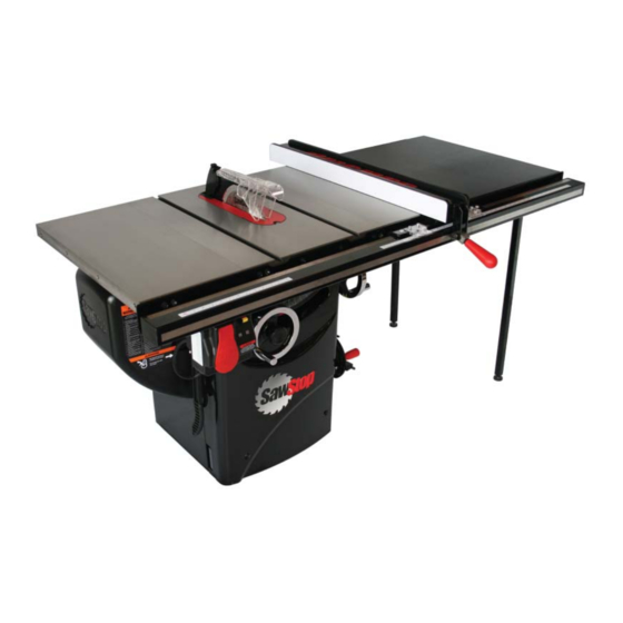
- Page 2 The saw on the front cover is shown with the optional 36 inch Professional Series II Fence Assembly. Your saw may look different. SawStop, the SawStop blade logo, and the confi guration of this product are either registered trademarks or trademarks of SawStop, LLC. Software copyright by SawStop, LLC. All rights reserved.
- Page 3 To Our Customers ® Thank you for purchasing a SawStop Professional Cabinet Saw! Your saw includes our revolutionary, award- winning safety system that tells the difference between cutting wood and cutting a person. If you ever accidentally contact the moving blade, the safety system will detect that contact and stop the blade in milliseconds to minimize any injury.
-
Page 4: Table Of Contents
Blade or Dado Installation Brake Position Adjustment Blade Guard and Riving Knife Installation Dust Collection Electrical Power Connection Re-Wiring a PCS175 Saw for 208-240V Power Changing the Plug or Power Cord on a 208-240V Saw SawStop 10” Professional Cabinet Saw... - Page 5 Using a Mobile Base Using an Out-Feed Table Changing the Brake Cartridge Installing a Brake Cartridge What to do if the SawStop ® Safety System Activates Making Adjustments to Your Saw Aligning the Table Aligning the Blade to the Tilt Axis...
- Page 6 Internal Assembly Exploded View Internal Assembly Parts List Arbor Assembly Exploded View Arbor Assembly Parts List Blade Guard and Miter Gauge Exploded View Blade Guard and Miter Gauge Parts List Literature, Hardware and Tools Parts List Accessories Index SawStop 10” Professional Cabinet Saw...
-
Page 7: Warranty
This warranty is void if the saw or any portion of the saw is modifi ed without the prior written permission of SawStop, LLC, or if the saw is located or has been used outside of the country of residence of the authorized SawStop distributor from whom the saw was purchased. -
Page 8: Safety And Warnings
A cord length over 50 feet is not recommended for 110- over 50 Feet Not Recommended 120V power. If in doubt, use the next heavier gauge. The smaller the gauge number the heavier the cord. SawStop 10” Professional Cabinet Saw... - Page 9 Professional Cabinet Saw Model PCS175 re-wired for 208-230V power is intended for use on a circuit that has an outlet that looks like the one illustrated in Sketch D. The saw has a grounding plug that looks like the plug illustrated in Sketch D.
- Page 10 22. DON’T FORCE THE TOOL. It will do the job better and safer at the rate for which it was designed. For example, do not try to cut wood faster than the motor can handle. SawStop 10” Professional Cabinet Saw...
- Page 11 27. Use only recommended accessories with the saw. Consult this manual for recommended accessories. The use of improper accessories may cause risk of injury. When servicing, use only identical replacement parts. 28. Keep the top of the saw clean and free from clutter. Cluttered areas invite accidents. SawStop 10” Professional Cabinet Saw...
-
Page 12: Warning Labels
WARNING warning labels are reproduced below: WARNING For your own safety, read the instruction manual To avoid loss of SawStop protection during coast down, before operating this saw. do not turn off Main Power until 1. Wear eye protection. blade has stopped spinning. -
Page 13: The Sawstop Safety System
® The SawStop Safety System ® This Professional Cabinet Saw is equipped with the SawStop safety system. This revolutionary technology was developed to reduce the potential for a serious injury in the event of accidental contact with the saw blade. -
Page 14: The Sawstop Safety System
® Never attempt to use a dado set or blade other than an 8 inch dado set with the SawStop dado cartridge. The use of smaller diameter blades with a brake cartridge designed for larger blades could result in a serious injury because the brake cannot be positioned correctly to stop the smaller blades. - Page 15 Similarly, stacks of two or more 10 inch blades should never be used on your SawStop saw as the combined weight of the blades may be too heavy to stop quickly. If you need to use a blade with a kerf thicker than ⁄...
-
Page 16: Unpacking Your Saw
WARNING! The saw weighs approximately 247 pounds without the extension wings and 317 pounds with the extension wings. Be careful in handling the saw to avoid injury. SawStop 10” Professional Cabinet Saw... - Page 17 Al cr us a se ca bi h or th e pi nc cu t, extension wings (two) 10” blade table saw (with pre-installed zero-clearance table insert, brake cartridge, and brake cartridge key) SawStop 10” Professional Cabinet Saw...
-
Page 18: Standing Up Your Saw
Styrofoam (see Fig. 2b). top piece of Styrofoam the bottom edge the edge of the of the saw should table should overhang the edge overhang the edge of the Styrofoam of the Styrofoam Fig. 2a Fig. 2b SawStop 10” Professional Cabinet Saw... - Page 19 (see Fig. 4). Lift the saw slowly so that it slides off the Styrofoam and onto the fl oor without damaging the cabinet. Fig. 4 SawStop 10” Professional Cabinet Saw...
-
Page 20: Assembling Your Saw
Be sure to remove all cardboard pieces from the inside of the cabinet. Fig. 6 SawStop 10” Professional Cabinet Saw... -
Page 21: Installing The Elevation Handwheel
. a se ca bin th e cu t, set screw elevation control shaft handwheel handwheel Fig. 10 elevation lock knob handwheel elevation lock knob Fig. 11 Fig. 12 SawStop 10” Professional Cabinet Saw... -
Page 22: Installing The Tilt Handwheel
Al cr us a se ca bi h or th e pi nc cu t, handwheel set screw handwheel Fig. 16 tilt lock knob handwheel tilt lock knob Fig. 17 Fig. 18 SawStop 10” Professional Cabinet Saw... -
Page 23: Installing The Dust Port
Do not operate with door open. shown in Fig. 21. Using a Phillips screwdriver, tighten each screw a little bit at a time until all three screws are securely in place. Fig. 21 SawStop 10” Professional Cabinet Saw... -
Page 24: Installing The Motor Cover
To open the motor cover press on the ribbed section on the front of the motor cover until it unlatches and swing the cover away from the cabinet. Reverse the process to close the cover (see Fig. 25). Fig. 25 SawStop 10” Professional Cabinet Saw... -
Page 25: Mounting The Extension Wings
Fig. 26 Use a straight-edge to level the extension wings with the cast iron table top and tighten all of the M8 x 20 hex bolts with a 13 mm wrench (see Fig. 27). Fig. 27 SawStop 10” Professional Cabinet Saw... -
Page 26: Mounting The Switch Box
M6 x 12 (2) holes M6 (2) Switch Box Keys (2) Blade Spacing Motor Adjustment Gauge (1) Cover Hex Key, M8 (1) Hex Keys: M3 (1), M4 (1), M5 (1), M6 (1) Tools Fig. 28 Fig. 29 SawStop 10” Professional Cabinet Saw... -
Page 27: Mounting The Accessory Holders
Tighten the screw with a 4mm hex key. Congratulations, your saw is now assembled. Note: You must install a rip fence prior to using the saw. Refer to the manual accompanying your rip fence for instructions on how to install the fence. SawStop 10” Professional Cabinet Saw... -
Page 28: Get To Know Your Saw
Tilt Angle Scale Switch Box Bypass Key Thermal Overload Switch Blade Wrenches (2) Miter Gauge Miter Gauge Slots Accessory Tool Holder Riving Knife Side Access Panel Motor Cover Dust Port Rear Access Panel Fig. 33 SawStop 10” Professional Cabinet Saw... - Page 29 Arbor Bumper Saw Blade Riving Knife Quick-Release Clamp Handle Arbor Nut Arbor Washer Brake Cartridge Cartridge Key Dust Shroud Dust Port Upper Elevation Limit Stop 0º Tilt Limit Stop 45º Tilt Limit Stop Fig. 35 SawStop 10” Professional Cabinet Saw...
-
Page 30: Preparing Your Saw For Use
WARNING! Never operate the saw without the table insert in place. CAUTION! Do not use table inserts with metal or other electrically-conductive parts that could contact the blade. This can cause the brake to be activated unnecessarily. SawStop 10” Professional Cabinet Saw... -
Page 31: Blade Or Dado Installation
You can use a dado set to cut a groove or slot in a workpiece. Other sizes or types of blades are not compatible with a SawStop saw. If you attempt to use an incompatible blade, the safety system will display an error code and prevent the motor from starting. -
Page 32: Brake Position Adjustment
Adjust the brake position as needed to set the spacing between the teeth of the blade and the closest point on the brake cartridge to between ⁄ ⁄ inch (see Fig. 40). Fig. 41 SawStop 10” Professional Cabinet Saw... - Page 33 After adjusting the brake position and before starting the saw, spin the blade by hand at least one full revolution to verify that the blade does not hit the brake (see Fig. 43). spin the blade by hand to make sure the blade does not touch the brake Fig. 43 SawStop 10” Professional Cabinet Saw...
-
Page 34: Blade Guard And Riving Knife Installation
WARNING! Use the blade guard and spreader for every operation for which it can be used, including all through-sawing. SawStop 10” Professional Cabinet Saw... - Page 35 Note: both the spreader and the riving knife are 2.3 mm (0.090 inch) thick. Do not use a saw blade with a kerf less than 2.35 mm with these tools. The kerf of a saw blade is the width of the cut produced by the blade. SawStop 10” Professional Cabinet Saw...
-
Page 36: Dust Collection
SawStop recommends the use of a dust collection system that provides at least 350 CFM of fl ow at the dust port. Attach a 4 inch diameter fl exible hose between the inlet port on your dust collector and the dust port at the ®... -
Page 37: Electrical Power Connection
The AC motor that comes with the Professional Cabinet Saw model PCS175 is rated at 1.75 hp and operates at 60 Hz. It can be used with 110-120V or 208-240V power. It comes from the factory pre-wired for 115V, which means it will work with 110-120V power. -
Page 38: Re-Wiring A Pcs175 Saw For 208-240V Power
Be sure to unplug your saw before proceeding. 2. Rewire the motor: The motor included on the PCS175 is a dual voltage motor. It is wired from the factory to run on 110-120V power. To convert the motor to run on 208-240V power, follow the steps below exactly: •... -
Page 39: V Wiring Diagram
Preparing Your Saw for Use Electrical Schematic for Re-Wiring a PCS175 Motor for 220-240V Power 110-120V Wiring Diagram Junction Box on Motor wire nut white black wire nut yellow motor white green black from contactor contactor 110-120 V 208-240V Wiring Diagram... -
Page 40: Changing The Plug Or Power Cord On A 208-240V Saw
Replacing the Power Cord Plug 230V contactor box assembly PCS-WA-025 which enables the Professional Cabinet Saw Model PCS175 to be used with 230V power comes with a NEMA 6-15P plug attached to the end of a 9 ft power cord. If you need to replace the plug with a different style plug, replace it with a 3-prong, 208-240V, UL-listed plug. - Page 41 (see Figs. 51 and 52). ground contactor power cord Fig. 51 Fig. 52 SawStop 10” Professional Cabinet Saw...
- Page 42 (see Fig. 54). A wiring diagram is shown in Fig. 55 on page 41. thermal circuit breaker contactor ground power cable Fig. 54 SawStop 10” Professional Cabinet Saw...
- Page 43 Preparing Your Saw for Use 230V PCS-WA-025 Contactor Box Wiring Diagram: THERMAL CIRCUIT BREAKER GROUND Green White Black CONTACTOR COIL COIL Green CONTACTOR BOX POWER MOTOR SWITCHBOX CABLE CABLE CABLE Fig. 55 SawStop 10” Professional Cabinet Saw...
-
Page 44: Using Your Saw
These limit stops are pre-set at the factory and should not need adjustment. If you decide to adjust the blade tilt limit stops, see tilt scale indicator page 75 for instructions. Fig. 57 SawStop 10” Professional Cabinet Saw... -
Page 45: Turning On Main Power And Starting The Motor
® Your SawStop saw is equipped with a main power switch to supply power to the SawStop safety system and a Start/Stop paddle to turn the motor on and off. Both the main power switch and the Start/Stop paddle are mounted on the switch box (see Fig. - Page 46 Double check the electrical circuit and all switch electrical connections and always use an contactor box appropriate feed rate for the material that you are cutting. Fig. 60 SawStop 10” Professional Cabinet Saw...
-
Page 47: System Status Codes
System Ready — this code indicates that all self-checks have been completed, the safety system is operating properly, and the saw is in Standby mode ready to run. SawStop 10” Professional Cabinet Saw... - Page 48 Standby mode. The brake will not be activated and the code will automatically clear within 5 seconds after contact is ended. The system will not allow the motor to start while this code is displayed. SawStop 10” Professional Cabinet Saw...
- Page 49 The overload error indicates that the system was close to fi ring the brake before it went into overload. Therefore, repeatedly attempting to cut a wet piece of wood could result in an unnecessary activation of the brake. SawStop 10” Professional Cabinet Saw...
-
Page 50: Using The Blade Guard
Lift to and then rotate up remove Fig. 63 Fig. 64 WARNING! Use the blade guard for every operation for which it can be used, including all through-sawing. SawStop 10” Professional Cabinet Saw... - Page 51 When not in use, the blade guard can be stored by inserting the bottom of the spreader in the outer slot of the accessory tool holder mounted to the side of the saw (see Fig. 33 on page 26). SawStop 10” Professional Cabinet Saw...
-
Page 52: Using The Riving Knife
The miter gauge is shown in use during a cross-cut in Fig. 72 on page 52. miter gauge in storage location Fig. 69 SawStop 10” Professional Cabinet Saw... - Page 53 Do not touch the portion of the workpiece that was cut off until the blade is stopped. WARNING! Never make freehand cuts. Never hold or touch an unsupported piece of wood while the blade is spinning. SawStop 10” Professional Cabinet Saw...
-
Page 54: Cross-Cutting
WARNING! To reduce the potential for kickback and a serious injury, move the rip fence out of contact with the workpiece when cross-cutting to prevent the workpiece from binding between the rip fence and the blade. SawStop 10” Professional Cabinet Saw... -
Page 55: Using A Fence
fl atness over time. The system also includes steel front and rear rails, a steel clamp tube, and SawStop’s proprietary design that makes the fence glide smoothly along the rail. This fence system is available in either a 36 or 52 inch version. -
Page 56: Rip Cutting
(See page 94 for instructions on making a push stick.) SawStop 10” Professional Cabinet Saw... - Page 57 Professional Series II fence where it is more easily accessible (see Fig. 78). push stick can be placed here push stick should be stored here Fig. 77 Fig. 78 SawStop 10” Professional Cabinet Saw...
- Page 58 (Fig. 80). A second featherboard can be clamped to the top of the table as discussed above, to hold the workpiece against the fence. Fig. 80 SawStop 10” Professional Cabinet Saw...
-
Page 59: Using The Saw In Bypass Mode
If that occurs and the saw is started, the shard could contact the aluminum brake pawl and cause the brake to activate. SawStop 10” Professional Cabinet Saw... -
Page 60: Using A Mobile Base
fl oor and lowered again. Fig. 83 ® ® You can learn more about the SawStop Professional Cabinet Saw Mobile Base and the SawStop Mobile ® Base Conversion Kit for use with the SawStop Industrial Mobile Base from an authorized SawStop distributor or at www.sawstop.com. -
Page 61: Using An Out-Feed Table
Professional Series II Fence System (see Fig. 84) and the Premium Fence Assembly (see Fig. 74 on page 53). Fig. 84 ® You can learn more about the SawStop Out-Feed Table from an authorized SawStop distributor or at www.sawstop.com. SawStop 10” Professional Cabinet Saw... -
Page 62: Changing The Brake Cartridge
® ® The SawStop brake cartridge (shown in Fig. 85) includes a sealed housing containing the SawStop system electronics, and an aluminum block called a brake pawl. The sealed housing also includes a high-speed actuator that pushes the brake pawl into the teeth of the saw blade in the event accidental contact is detected. - Page 63 The cartridge mounting bracket also holds a computer cable that self-aligns to the connector in the side of the cartridge. A cartridge key is used to lock the brake cartridge in place against the cartridge mounting bracket. positioning cartridge Fig. 88 SawStop 10” Professional Cabinet Saw...
- Page 64 A signifi cant force may be needed to pry the cartridge off the mounting pin if the brake pawl deformed and pinched the pivot pin when it stopped the blade. SawStop 10” Professional Cabinet Saw...
-
Page 65: Installing A Brake Cartridge
An improperly positioned brake could increase the time required to stop the blade in the event of accidental contact, or cause the brake to actuate unexpectedly if the blade comes into contact with the brake. SawStop 10” Professional Cabinet Saw... -
Page 66: What To Do If The Sawstop Safety System Activates
What to do if the SawStop Safety System Activates When the SawStop safety system is activated, the brake pawl will be pushed into the blade to stop its rotation. If the blade is spinning at a signifi cant speed, the arbor block will retract to lower the blade below the table. Both of these actions will occur within just a few milliseconds. -
Page 67: Making Adjustments To Your Saw
Making Adjustments to Your Saw Your SawStop Professional Cabinet Saw has been factory adjusted to rigid specifi cations to provide the highest quality performance and results. Additional adjustment or alignment should not be necessary. Nevertheless, your SawStop Professional Cabinet Saw has been designed to allow a wide range of adjustments and alignments to achieve the ultimate in precision. - Page 68 For measurements larger than 0.002 inch, you can adjust the position of the table to improve the parallelism between the blade and the miter slot. SawStop 10” Professional Cabinet Saw...
- Page 69 “star pattern” until all are tight. Watch the dial indicator while tightening, and if one bolt causes a signifi cant change, tighten the other bolts fi rst. SawStop 10” Professional Cabinet Saw...
- Page 70 Preferred Table Alignment Procedure. Repeat the above measurements and table alignment until you are satisfi ed with the parallelism between the blade and the miter slot. Finally, tighten the table mounting bolts. Fig. 99 SawStop 10” Professional Cabinet Saw...
-
Page 71: Aligning The Blade To The Tilt Axis
0º (this assumes the table has been aligned to be parallel ® to the blade at 0º tilt angle). SawStop cabinet saws are the only major cabinet saws that allow you to fi ne tune the parallelism of the blade to the tilt axis. - Page 72 The angle of the blade relative to the tilt axis is controlled by two bolts that bolt the secondary elevation shaft to the rear trunnion (see in Fig. 102). bottom bolt secondary elevation shaft Fig. 102 SawStop 10” Professional Cabinet Saw...
- Page 73 0.002 inch at both 0º and 45º, then the blade is parallel to the tilt axis. If necessary, you can fi ne tune the alignment by repeating the above procedure. SawStop 10” Professional Cabinet Saw...
-
Page 74: Aligning The Blade Elevation Assembly
Although all table saws suffer from some lateral blade movement due to tolerance stack-ups in machining, only SawStop cabinet saws allow you any adjustment to minimize this problem. WARNING! Always turn off the main power switch and unplug the power cord before making any adjustments to your saw. - Page 75 0º tilt angle as described on page 65. Then continue the alignment process by re-aligning the blade to the tilt axis (see page 69) and then re-aligning the blade Fig. 105 elevation assembly (see page 72). SawStop 10” Professional Cabinet Saw...
-
Page 76: Adjusting The Elevation Limit Stops
Finally, turn the upper elevation locking nut clockwise until it is tight. The upper limit stop elevation limit has now been set. Fig. 107 SawStop 10” Professional Cabinet Saw... -
Page 77: Adjusting The Tilt Limit Stops And Tilt Angle Indicator
Next, turn the 0° limit bolt clockwise until it is tight. Finally, turn the locking nut clockwise until it is tight. The 0° tilt limit stop has now been set. 0° tilt locking limit stop Fig. 109 SawStop 10” Professional Cabinet Saw... - Page 78 0°. It may be helpful locking tilt angle to remove the elevation handwheel to screws indicator Fig. 111 access the screws. Lock the indicator in place by tightening the locking screws. SawStop 10” Professional Cabinet Saw...
-
Page 79: Adjusting The Table Insert
(see Fig. 112). If the insert is too tight, turn the side and/or rear positioning screw(s) clockwise as needed to increase the clearance between the insert and the table opening. SawStop 10” Professional Cabinet Saw... - Page 80 The height of the lock-down screws can be adjusted using the included 3 mm hex key. table lock-down rear rear screws leveling leveling screw screw Fig. 114 SawStop 10” Professional Cabinet Saw...
-
Page 81: Aligning The Riving Knife And Spreader To The Blade
(using an 8 mm hex key) just enough so that you can slide the clamp along its mounting surface with some friction. Reinstall the blade and raise the blade to the fully elevated position. mounting bolts Fig. 117 SawStop 10” Professional Cabinet Saw... - Page 82 Fig. 119 WARNING! Always turn off the main power switch and unplug the power cord before making any adjustments to your saw. SawStop 10” Professional Cabinet Saw...
- Page 83 4-7 mm. Once the clamp has been properly positioned, further adjustment should not be necessary. Both the spreader and riving knife will now automatically align when installed in the clamp. SawStop 10” Professional Cabinet Saw...
-
Page 84: Adjusting The Quick-Release Clamp
If the pressure is too low these important safety devices may not function properly and a serious injury could result. In addition, the spreader or riving knife may come into contact with the blade and cause an unintended activation of the safety system. SawStop 10” Professional Cabinet Saw... -
Page 85: Adjusting The Miter Gauge
Finally, tighten the locking nut to prevent the set screw from moving. indexing Repeat the above process for the other indexing Fig. 123 stops if desired. SawStop 10” Professional Cabinet Saw... -
Page 86: Adjusting The Motor Belt Tension
45º. If there is extra play when turning the handwheel, tighten the set screw farther, but if the handwheel binds or is diffi cult to turn set screw then the set screw should be loosened. Fig. 125 SawStop 10” Professional Cabinet Saw... -
Page 87: Adjusting The Elevation Gearing
If there is extra play when turning the handwheel, tighten the set screws farther, but if the handwheel binds or is diffi cult to turn then the set screws pinion gear should be loosened. Fig. 127 SawStop 10” Professional Cabinet Saw... -
Page 88: Maintenance
84. The arbor belt cannot be tightened, and therefore must be replaced if it does not have suffi cient tension to prevent slipping under load. SawStop 10” Professional Cabinet Saw... -
Page 89: Lubrication Points
45º. rear trunnion bracket elevation handwheel shaft bushing sector gear Fig. 128 front trunnion bracket threaded rod tilt handwheel shaft bushing pinion gear worm gear Fig. 129 SawStop 10” Professional Cabinet Saw... -
Page 90: Troubleshooting
4. The voltage supplied to the motor is Ensure the motor is wired to match incorrect. the power that is being supplied. If using an extension cord, ensure the extension cord is the correct gauge. SawStop 10” Professional Cabinet Saw... - Page 91 2. The shaft of the cartridge key is 2. Try turning and removing the key while binding in the cartridge or on the pressing upward or downward on the cartridge mounting bracket. key or cartridge. SawStop 10” Professional Cabinet Saw...
- Page 92 2. The fl oor is uneven. 2. Move the saw to a level, even surface. The saw vibrates too much. 3. The bearings are worn. 3. Replace the bearings. The belts are worn. Replace the belts. SawStop 10” Professional Cabinet Saw...
-
Page 93: Professional Cabinet Saw Specifi Cations
Blade guard: polycarbonate, extends only 1” to right of blade Standard Insert: zero-clearance, phenolic core, melamine surfaces Belts: 2 V-ribbed belts— arbor belt is static dissipative Handwheels: 7” diameter, cast iron chrome plated Motor options: 1.75hp SawStop 10” Professional Cabinet Saw... -
Page 94: Professional Cabinet Saw Dimensions
SawStop 10” Professional Cabinet Saw... - Page 95 SawStop 10” Professional Cabinet Saw...
-
Page 96: Push Stick Construction
SawStop 10” Professional Cabinet Saw... -
Page 97: Auxiliary Fence Construction
SawStop 10” Professional Cabinet Saw... -
Page 98: Push Block Construction
SawStop 10” Professional Cabinet Saw... -
Page 99: Featherboard Construction
SawStop 10” Professional Cabinet Saw... -
Page 100: Drawings And Parts Lists
SawStop 10” Professional Cabinet Saw... -
Page 101: Cabinet And Table Parts List
M5x10x1 Washer PCS-035 Switch Box Cable Grommet PCS-036 Side Cabinet Access Door PCS-037 Cabinet Access Door Lock Knob PCS-038 M6 Lock Knob Retaining Washer PCS-039 M6x1.0x10 Button Head Socket Screw PCS-040 M10x1.5x25 Hex Head Bolt PCS-041 SawStop 10” Professional Cabinet Saw... - Page 102 Blade Retraction Warning Label PCS-063 Gear Warning Label PCS-064 Patent Label PCS-065 Specifi cation Label PCS-067 Main Warning Label PCS-257 Main Power Label PCS-069 System Status Label PCS-070 Table Insert Warning Label PCS-071 Professional 1.75HP Model Label PCS-259 SawStop 10” Professional Cabinet Saw...
- Page 103 This page is blank. SawStop 10” Professional Cabinet Saw...
-
Page 104: Internal Assembly Exploded View
SawStop 10” Professional Cabinet Saw... -
Page 105: Internal Assembly Parts List
PCS-103 Tilt Indicator PCS-104 M6x1.0x15 Button Head Socket Screw PCS-105 Tilt Handwheel Lock Knob PCS-106 Handwheel Handle PCS-107 Handwheel PCS-108 M6x1.0x8 Set Screw PCS-109 M5x5x25 Key PCS-110 Control Shaft Key PCS-111 Elevation Control Shaft PCS-245 SawStop 10” Professional Cabinet Saw... - Page 106 PCS-145 Elevation Gear Shaft Mounting Bracket PCS-146 Elevation Gear Shaft PCS-147 M6x15x1.5 Washer PCS-148 Elevation Pinion Gear PCS-149 Spreader Mounting Plate PCS-150 M10x1.5x25 Socket Cap Screw PCS-151 M8x1.0 Hex Nut PCS-152 Spreader Positioning Plate PCS-153 SawStop 10” Professional Cabinet Saw...
- Page 107 M5.2x10 Spring Pin PCS-168 M6x1.0x30 Socket Cap Screw PCS-169 M6x22 Pin PCS-242 Elevation Control Shaft Collar PCS-247 M5x0.8x16 Socket Cap Screw PCS-248 M20x32x2 Washer PCS-249 M6x1.0x10 Custom Set Screw PCS-250 M6x1.0x25 Socket Cap Screw PCS-261 SawStop 10” Professional Cabinet Saw...
-
Page 108: Arbor Assembly Exploded View
Arbor Assembly Exploded View SawStop 10” Professional Cabinet Saw... -
Page 109: Arbor Assembly Parts List
PCS-201 Arbor Belt PCS-202 Motor Belt PCS-203 Cartridge Cable PCS-204 Cartridge Bracket PCS-205 M6x1.0x12 Button Head Shoulder Screw PCS-206 Threaded Pin PCS-207 M8x20x2 Washer PCS-208 M8x1.25 Lock Nut PCS-209 M4x0.7x20 Flat Head Socket Screw PCS-210 SawStop 10” Professional Cabinet Saw... - Page 110 M4x0.7 Lock Nut PCS-213 M5x0.8x8 Set Screw PCS-214 Brass Pressure Ring PCS-215 Brake Cartridge for 10” Blade TSBC-10R2 Brake Cartridge Key PCS-217 Blade Spacing Attention Tag PCS-218 M5x0.8x8 Pan Head Phillips Screw (with M5 lock washer) PCS-219 SawStop 10” Professional Cabinet Saw...
- Page 111 This page is blank. SawStop 10” Professional Cabinet Saw...
-
Page 112: Blade Guard And Miter Gauge Exploded View
SawStop 10” Professional Cabinet Saw... -
Page 113: Blade Guard And Miter Gauge Parts List
Indexing Pin PCS-224 O-Ring PCS-225 Miter Gauge Head PCS-226 8-32 NCx5/8” Phillips Head Screw PCS-227 8-32 NC Nut PCS-228 Miter Gauge Handle PCS-229 M8x18x3 Washer PCS-230 Miter Gauge Bar PCS-252 Gauge Head Mounting Screw PCS-232 SawStop 10” Professional Cabinet Saw... -
Page 114: Literature, Hardware And Tools Parts List
M5x0.8x12 Spring Bearing PCS-251 Literature, Hardware and Tools Parts List Description Part No. Qty. PCS175 10” Professional Saw Owner’s Manual PCS-254 Table Saw Hardware Pack PCS-236 PCS175 Unpacking Procedure Poster PCS-255 Hex Key Tool Holder (includes M3, M4, M5, M6 hex keys) -
Page 115: Accessories
® SawStop recommends the following accessories for use with your SawStop Professional Cabinet Saw. Contact your local authorized SawStop Dealer or SawStop at 1-866-SAWSTOP for more information. 1. SawStop Brake Cartridges: Standard Brake Cartridge for 10 inch saw blades TSBC-10R2... -
Page 116: Index
(see Dado Sets) damaged: 12, 64 elevation (see Elevation) kerf: 33, 50, 79-80, 91 non-conductive: 12, 29, 46 retraction: 11, 13, 64 standard blade: 12, 29, 60, 113 with depth-limiting shoulders: 12, 29 SawStop 10” Professional Cabinet Saw... - Page 117 12-13, 29, 60, 8, 113 cuts: 12, 48, 50, 56, 60 insert: 29, 113 set: 12-13, 29, 33, 60, 62, 63, 89, 91 Depth of Cut: 51, 91 Detection of Accidental Contact: 1, 5, 11-13, 45-47, 64 SawStop 10” Professional Cabinet Saw...
- Page 118 Electrical grounding: 6, 35 power connection: 6-7, 13, 35, 44, 88 contactor box wiring diagram: 41 schematic for re-wiring a PCS175 motor for 208-240V power: 37 Elevation changing the blade elevation: 42 elevation handwheel: 14, 19, 26, 42, 90, 91...
- Page 119 Motor Belt: 27, 46, 84, 86, 88, 90 Motor Cover: 15, 22, 26 Out-Feed Table: 59 Overload (of the detection system): 45, 47 Parts Lists arbor : 107-108 blade guard and miter gauge: 111-112 cabinet and table: 99-100 SawStop 10” Professional Cabinet Saw...
- Page 120 Rear Access Panel: 26 Rear Trunnion: 27, 72 Rear Trunnion Bracket: 27, 69 Retraction: 11, 13, 64 Re-Wiring a PCS175 Saw for 208-240V Power: 36-37 cutting: 54-56 fence: 8, 25, 53, 54-56, 88, 113 narrow rip cuts: 48 Riving Knife...
- Page 121 Wet Wood: 13, 45, 47, 88 Wiring (see Electrical, power connection and schematic) Worm (see Elevation, worm or Tilt, worm) Worm Gear (see Elevation, worm gear) : 85, 86-87, 90 Wrench holder: 25, 26 Zero-Clearance Table Insert (see Table Inserts) SawStop 10” Professional Cabinet Saw...
- Page 122 This page is blank. SawStop 10” Professional Cabinet Saw...
- Page 123 SawStop, LLC 9564 S.W. Tualatin Road Tualatin, Oregon 97062 USA www.sawstop.com Main Phone - (503) 570-3200 Service - (503) 582-9934 Fax - (503) 570-3303 Email: info@sawstop.com September 2013...
Need help?
Do you have a question about the PCS175 and is the answer not in the manual?
Questions and answers
my sawstop saw tilts to 20 deg and thin it's like the gear is stripped it justs bounces
If the SawStop PCS175 saw tilts to 20 degrees and bounces as if the gear is stripped, it may be due to a problem with the tilt mechanism components such as the tilt handwheel, sector gear, worm gear, or threaded rod. These parts are involved in adjusting and holding the blade at the desired tilt angle. If they are worn, damaged, or not properly lubricated, the tilt movement may not be smooth, causing bouncing or slipping. Checking for damage and ensuring proper lubrication of the tilt mechanism is recommended.
This answer is automatically generated