Table of Contents
Advertisement
Advertisement
Table of Contents

Related Manuals for SawStop CB31230


Summary of Contents for SawStop CB31230
- Page 1 OWNER’S MANUAL 10” CABINET SAW Models CB31230, CB33230, CB51230,CB53230, CB53480...
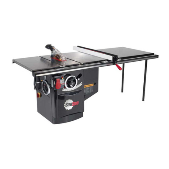
- Page 2 Copyright 2004, SawStop, LLC Patents Pending All Rights Reserved. 1st printing, December 2004 Updates of this manual may be available at www.sawstop.com The saw shown on the front cover includes the optional 36” fence and extension table. Your saw may look different.
- Page 3 To Our Customers Thank you for purchasing a SawStop cabinet saw! It is the safest, most technically advanced table saw ever made. As you will soon discover, the features of the SawStop cabinet saw establish new standards in the table saw industry.
-
Page 4: Table Of Contents
10. Connection of Dust Collection: 11. Electrical Power Connection: 11. Disconnect Switch: Using Your Saw 1. Adjusting the Blade Height: 2. Adjusting the Blade Tilt Angle: 3. Turning on Main Power and Starting the Motor: 4. System Status Codes: SawStop 10” Professional Cabinet Saw... - Page 5 8. Using the Miter Gauge: 9. Cross-Cutting: 10. Rip Cutting: 11. Changing the Brake Cartridge: What to do if the SawStop Safety System Activates Making Adjustments to Your Saw 1. Aligning the Blade Elevation Assembly: 2. Aligning the Table: 3. Aligning the Blade to the Tilt Axis: 4.
- Page 6 Cabinet and Table Assembly Parts List Internal Assembly Exploded View Internal Assembly Parts List Arbor Assembly Exploded View Arbor Assembly Parts List Miter Gauge and Blade Guard Assemblies Exploded View Miter Gauge and Blade Guard Assemblies Parts List Accessories Index SawStop 10” Professional Cabinet Saw...
-
Page 7: Warranty
You may incur a serious injury on a SawStop saw. If you decide to use the saw in Bypass mode, the safety system will be disabled and it will not activate in the event you contact the spinning blade. -
Page 8: Safety
Do not use the saw in dangerous environments. For example, do not use the saw in damp or wet locations or expose it to rain; and keep the work area well lighted. Keep children away from the saw. Make the workshop kid-proof with padlocks, master switches, or by removing starter keys. SawStop 10” Professional Cabinet Saw... - Page 9 21. This saw is packaged without a rip fence. You must install a rip fence before using this saw. Attempting to use the saw without a rip fence could result in a serious personal injury. 22. Always maintain firm control over the material being cut. Never cut any material freehand. SawStop 10” Professional Cabinet Saw...
-
Page 10: Warning Labels
Do not try to disable the brake system. Unplug the saw before changing the blade, changing the brake cartridge or servicing. Do not connect the motor directly to a power supply. Use the bypass switch only when necessary. SawStop 10” Professional Cabinet Saw... - Page 11 ���� ����� ������� ������ ���������� (On saws with 230V, single phase motors.) WARNING WARNING To avoid loss of SawStop protection during coast down, Connect Only 208-240 Volts, do not turn off Main Power until blade has stopped spinning. Single Phase Power.
-
Page 12: The Sawstop Safety System
This revolutionary technology was developed to ® reduce the potential for a serious injury in the event of accidental contact with the saw blade.SawStop table saws are the first saws ever built to be smart enough to know the difference between you and the wood you are cutting. - Page 13 ® cartridge. Never attempt to use a dado set or blade other than an 8 inch dado set with the SawStop dado cartridge. The use of smaller diameter blades with a brake cartridge designed for larger blades could result in a serious injury because the brake cannot be positioned correctly to stop the smaller blades.
- Page 14 12. Do not use table inserts, guards, fences or other devices which have metal parts that may come into ® contact with the blade. Any metal part that contacts the blade may cause the brake to activate. All SawStop accessories are specifically designed to prevent metal contact with the blade.
-
Page 15: Unpacking Your Saw
14. One owner’s manual. 15. Two hand wheels (the handle on the tilt hand wheel is not pre-installed) Other accessories such as a fence and rails, an extension table, extra brake cartridges, etc., are packaged separately. SawStop 10” Professional Cabinet Saw... -
Page 16: Get To Know Your Saw
Terminal Box Fig. 2 Dust Port Miter Gauge Blade Wrenches (2) Belt Access Door Bypass Key Spreader / Riving Knife Storage Pin Miter Gauge Slots Tilt Angle Indicator Tilt Angle Scale Disconnect Switch Fig. 3 SawStop 10” Professional Cabinet Saw... - Page 17 Upper Elevation Limit Bolt Lower Elevation Limit Bolt 0° Tilt Limit Bolt 45° Tilt Limit Bolt Brake Positioning Bolt Brake Cartridge Cartridge Key Spreader / Riving Knife Clamping Handle Riving Knife Elevation Threaded Rod Fig. 5 SawStop 10” Professional Cabinet Saw...
-
Page 18: Cabinet Saw Specifications
3 hp, 3 phase, 230 V, 50-60 Hz, TEFC (optional) 5 hp, 1 phase, 230 V, 50-60 Hz, TEFC (optional) 5 hp, 3 phase, 230 V, 50-60 Hz, TEFC (optional) 5 hp, 3 phase, 480 V, 50-60 Hz, TEFC (optional) SawStop 10” Professional Cabinet Saw... -
Page 19: Setting Up Your Saw
This saw ships without a rip fence. You must install a rip fence prior to using the saw. Refer to the manual that accompanied your rip fence for instructions on installing the fence on the saw. SawStop 10” Professional Cabinet Saw... -
Page 20: Tilt Hand Wheel Handle Installation
After removing the arbor nut and arbor washer, install the blade and reinstall the arbor washer and arbor nut. Use the blade wrenches to tighten the arbor nut securely (see Fig. 8). Fig. 8 SawStop 10” Professional Cabinet Saw... -
Page 21: Brake Position Adjustment
WARNING! Do not attempt to use saw blades made of materials that are electrically non- conductive (e.g., abrasive blades, blades with plastic hubs, etc.). The SawStop ® safety system will not allow the saw to operate if these blades are installed. - Page 22 1/16th and 1/8th inch (see Fig. 11). brake positioning bolt A close-up of the area inside the circle is shown in Fig. 12, on page 21. Fig. 11 SawStop 10” Professional Cabinet Saw...
-
Page 23: Blade Guard / Riving Knife Installation
Fig. 13 SawStop 10” Professional Cabinet Saw... - Page 24 For instructions on the operation and use of the blade guard and the riving knife, please see page 34. Note: both the spreader and the riving knife are 2 mm (0.079 in) thick. Do not use a saw blade with a kerf less than 2 mm with these tools. SawStop 10” Professional Cabinet Saw...
-
Page 25: Table Insert Installation
Fig. 16 WARNING! Never operate the saw without the table insert in place. CAUTION! Do not use table inserts made of metal or other electrically-conductive materials. This can cause the brake to be activated unnecessarily. SawStop 10” Professional Cabinet Saw... -
Page 26: Connection Of Dust Collection
(see Fig. 17). It is important to connect a suitable dust collection system to the dust port on the exterior of the cabinet. All table saws generate a substantial amount of the dust, which can be a serious physical hazard. SawStop recommends the use of a dust collection system that provides at least 350 CFM of flow at the dust port. -
Page 27: Electrical Power Connection
WARNING! this saw must be connected to a grounded metal permanent wiring system; or to a system having an equipment-grounding conductor. Failure to connect this saw to an adequate electrical ground may cause the safety system to malfunction and could result in a serious injury or electric shock. SawStop 10” Professional Cabinet Saw... -
Page 28: Disconnect Switch
When the disconnect switch is switched to OFF (see Fig. 19), electrical power is physically disconnected from both the SawStop safety system and the magnetic contactor box. The disconnect switch should be switched to OFF whenever performing any adjustments, maintenance or repairs to the saw, including changing blades, installing or removing the blade guard and riving knife, etc. -
Page 29: Using Your Saw
0 and 45 degree setpoints. These limit stops are pre-set at the factory and should not need adjustment. If you wish to adjust the blade tilt limit stops, see page 59 for instructions. Fig. 23 SawStop 10” Professional Cabinet Saw... -
Page 30: Turning On Main Power And Starting The Motor
Electrical Disconnect Switch to supply power to the saw, a Main ® Power Switch to supply power to the SawStop safety system, and a Start/Stop paddle to turn the motor on and off. Both the Main Power switch and the Start/Stop paddle are mounted on the Switch Box, which is located just below the front edge of the table and to the left of the elevation hand wheel (see Fig. - Page 31 (see Fig. 25). When the key is removed, the Main Power Switch can be turned OFF, but it cannot be turned ON. main power switch lockout key Fig. 25 SawStop 10” Professional Cabinet Saw...
-
Page 32: System Status Codes
Red LED is on solid WARNING! Always turn the Main Power Switch to OFF and disconnect the saw from the power supply before changing the blade or performing any other adjustments or maintenance to the saw. SawStop 10” Professional Cabinet Saw... - Page 33 Standby mode. The brake will not be activated and the error will automatically clear within 5 seconds after contact is ended. The system will not allow the motor to start while this error is occurring. SawStop 10” Professional Cabinet Saw...
- Page 34 The wood should be set aside to allow it to dry before continuing the cut. If necessary, you can cut the wood in Bypass Mode to prevent this error. (See page 33 for instructions on how to operate the saw in Bypass Mode.) SawStop 10” Professional Cabinet Saw...
-
Page 35: Using The Saw In Bypass Mode
Fig. 26 cleared. WARNING! Never run the saw in Bypass Mode unless necessary to cut conductive materials. The brake system will not activate when the saw is in Bypass Mode and a serious injury could result. SawStop 10” Professional Cabinet Saw... -
Page 36: Using The Blade Guard
Most table saw injuries occur when the blade guard is either not being used or not being used properly. Your SawStop saw is equipped with a narrow profile blade guard that allows you to use the rip fence when making narrow rip cuts. -
Page 37: Using The Riving Knife
Fig. 29 storage location SawStop 10” Professional Cabinet Saw... - Page 38 Do not touch the portion of the workpiece that was cut off until the blade has completed coast-down. WARNING! never make free-hand cuts. Never hold or touch an unsupported piece of wood while the blade is spinning. SawStop 10” Professional Cabinet Saw...
-
Page 39: Cross-Cutting
WARNING! to reduce the potential for kickback and a serious injury, move the rip fence out of contact with the workpiece when cross-cutting to prevent the workpiece from binding between the rip fence and the blade.. SawStop 10” Professional Cabinet Saw... -
Page 40: Rip Cutting
(See page 73 for instructions on making a push stick.) WARNING! to reduce the chance of a serious injury, always use a push stick when making rip cuts narrower than 6 inches. SawStop 10” Professional Cabinet Saw... - Page 41 Fig. 35. In the illustration, a second featherboard can be clamped to the top of the table and against the left side of the workpiece to hold the workpiece against the rip fence. Fig. 35 SawStop 10” Professional Cabinet Saw...
- Page 42 In this case, leave the blade or dado set on the arbor and continue with the instructions below. If the brake cartridge has not been actuated, remove the blade or dado set from the arbor as described on page 18. SawStop 10” Professional Cabinet Saw...
-
Page 43: Changing The Brake Cartridge
Using Your Saw 11. Changing the Brake Cartridge: The SawStop standard brake cartridge (shown in Fig. 37) includes a sealed housing containing the SawStop system electronics, and an aluminum block called a brake pawl. The sealed housing also includes a high- speed actuator that pushes the brake pawl into the teeth of the saw blade in the event accidental contact is detected. - Page 44 It may take a small amount of force to turn the key and pull it out. Make sure you turn the key 90°, as the key cannot be pulled out unless it has been fully rotated. Fig. 40 SawStop 10” Professional Cabinet Saw...
- Page 45 1/2” by 16”) along the side the blade and against the portion of the brake pawl that is locked on the blade. Using a mallet, hit the other end of the stick until the blade completely clears the brake pawl. Fig. 42 SawStop 10” Professional Cabinet Saw...
- Page 46 An improperly positioned brake could increase the time required to stop the blade in the event of accidental contact, or cause the brake to actuate unexpectedly if the blade comes into contact with the brake. SawStop 10” Professional Cabinet Saw...
-
Page 47: What To Do If The Sawstop Safety System Activates
What to do if the SawStop Safety System Activates When the SawStop Safety System is activated, the brake pawl will be pushed into the blade to stop its rotation and the arbor block will retract to lower the blade below the table. Both of these actions will occur within just a few milliseconds. -
Page 48: Making Adjustments To Your Saw
The SawStop cabinet saw uses a vertical slide elevation design for ultra smooth operation and rigidity. As shown in Fig. 43, the blade and arbor block are mounted on a large cast iron base called the elevation plate. - Page 49 If there is similar change but in the opposite direction, this indicates that the left and right surfaces of the blade are not parallel. Rotate the blade 1/4 turn and repeat the process from the beginning. If you cannot get consistent readings, try a different blade. SawStop 10” Professional Cabinet Saw...
- Page 50 If the difference is greater than 0.002 inch, you can adjust the alignment of the rear shaft relative to the front shaft to reduce the error. Fig. 45 SawStop 10” Professional Cabinet Saw...
- Page 51 To confirm that the shafts are now parallel, you can repeat the procedure described above from the beginning. Occasionally the alignment procedure will make a small change to the first measurement. If necessary, realign the rear shaft until the difference between the first and second measurements is negligible. SawStop 10” Professional Cabinet Saw...
-
Page 52: Aligning The Table
1/4 inch above the center of the arbor flange. Slide the mount forward until the measurement arm is about 1/2 inch inside the front edge of the blade. See Fig. 48. Fig. 48 SawStop 10” Professional Cabinet Saw... - Page 53 You should see the readout on the dial indicator change as you adjust the positioning screws. Adjust the screws until the readout is the same, but in the reverse direction. For example, if the initial reading was +0.006 inch, adjust the positioning screw until the reading is - 0.006 inch. SawStop 10” Professional Cabinet Saw...
- Page 54 flat against the right side of the blade, and position the base to be flush against the left side of the right-hand miter slot. See Fig. 50. Write the measurement down. combination square Fig. 50 SawStop 10” Professional Cabinet Saw...
-
Page 55: Aligning The Blade To The Tilt Axis
0º (this assumes the table has been aligned to be parallel to the blade at 0º tilt angle). The SawStop cabinet saw is the only major cabinet saw that allows you to fine tune the parallelism of the blade and the tilt axis. - Page 56 Now, slide the dial indicator toward the rear of the saw until the measurement arm is about 1/2 inch inside the rear edge of the blade. Set the readout to zero. SawStop 10” Professional Cabinet Saw...
- Page 57 0° tilt angle is - 2.5 times the misalignment measured at a 45° tilt angle. For example: if the misalignment at 45° was +0.006 inch, then the misalignment at 0° should be adjusted to ( - 2.5) (0.006) = - 0.015 inch SawStop 10” Professional Cabinet Saw...
- Page 58 If the misalignment of the blade and the miter slot is less than 0.002 inch at both 0° and 45°, then the blade is parallel to the tilt axis. SawStop 10” Professional Cabinet Saw...
-
Page 59: Adjusting The Elevation Limit Stops
Turn the upper limit bolt clockwise until it is tight. Finally, turn the locking nut clockwise until it is tight. The upper elevation limit stop has now been set. Fig. 57 upper elevation limit stop SawStop 10” Professional Cabinet Saw... - Page 60 Next, set the blade elevation to the correct minimum height. Turn the lower limit bolt clockwise until it is tight. Finally, turn the locking nut clockwise until it is tight. The lower elevation limit stop has now been set. SawStop 10” Professional Cabinet Saw...
-
Page 61: Adjusting The Tilt Limit Stops And Tilt Angle Indicator
90° to the table. Turn the 0° limit bolt clockwise until it is tight. Finally, turn the locking nut clockwise until it is tight. The 0° limit stop has now been set. Fig. 60 SawStop 10” Professional Cabinet Saw... -
Page 62: Tilt Angle Indicator
(see Fig. 63 on page 61). You can access the bolt by opening the motor cover. It will also be necessary to decrease the tilt angle to about 30° to access the 45° limit bolt. Fig. 62 SawStop 10” Professional Cabinet Saw... -
Page 63: Adjusting The Table Insert
6. Adjusting the Table Insert: The SawStop zero clearance insert has been designed to fit securely within the table opening and just below the table top. The insert is pre-cut at the factory with a 10 inch blade after all alignments to the saw have been completed. -
Page 64: Aligning The Riving Knife And Spreader To The Blade
To adjust the clamp, set the tilt angle to 0° and remove the table insert. Make sure the spreader is installed, and lower the blade elevation to zero. Remove the blade and set it aside for a moment. horizontal positioning bolts Fig. 66 SawStop 10” Professional Cabinet Saw... - Page 65 Next, loosen the vertical positioning bolts using the included 5 mm hex L- wrench. Loosen the bolts just enough to allow the clamp to slide up and down on the clamp mounting bracket. Reinstall the blade. SawStop 10” Professional Cabinet Saw...
- Page 66 WARNING! make sure there is at least 1mm spacing between the riving knife and blade at all points. Contact between the blade and either the riving knife or spreader during operation will cause the brake system to be activated. SawStop 10” Professional Cabinet Saw...
-
Page 67: Adjusting The Tilt Gearing
Tighten the mounting bolts and test the tilt mechanism to confirm that it is properly adjusted. sector gear worm gear tilt control shaft tilt shaft bracket Fig. 69 mounting bolts SawStop 10” Professional Cabinet Saw... -
Page 68: Adjusting The Miter Gauge
Finally, tighten the locking nut to prevent locking nut the set screw from moving. Repeat the above process for the other indexing stops if desired. set screw indexing pin Fig. 71 SawStop 10” Professional Cabinet Saw... -
Page 69: Troubleshooting
3. The riving knife / blade guard clamp 3. Swing the clamp handle fully upward handle is in the way. to clear the cartridge. 4. The trunnion brace is in the way. 4. Raise the blade elevation fully. SawStop 10” Professional Cabinet Saw... - Page 70 SawStop 10” Professional Cabinet Saw...
- Page 71 The motor starts slowly and/or fails to 2. The electrical supply line to the saw 2. Ensure that the line that supplies reach nominal speed. is under-rated. power to the saw is sufficient for the required voltage and current. SawStop 10” Professional Cabinet Saw...
-
Page 72: Maintenance
If light finger pressure on one side of the belt causes more than about 1/2” deflection, the belt should be tightened. The arbor belt cannot be tightened, and therefore must be replaced if it does not have sufficient tension to prevent slipping under load. SawStop 10” Professional Cabinet Saw... -
Page 73: Cabinet Saw Dimensions
SawStop 10” Professional Cabinet Saw... - Page 74 SawStop 10” Professional Cabinet Saw...
-
Page 75: Push Stick Construction
SawStop 10” Professional Cabinet Saw... -
Page 76: Featherboard Construction
SawStop 10” Professional Cabinet Saw... -
Page 77: Electrical Schematic - 230V, Single-Phase (3 And 5 Hp)
13NO COIL COIL *This saw does not require a neutral line. SawStop recommends the use of a 3-wire cable or conduit, with the black and white wires connected to power 14NO and the green wire connected to a grounded metal permanent wiring system or equipment ground. -
Page 78: Electrical Schematic - 230V, Three-Phase (3 And 5 Hp)
TERMINAL BOX SURGE SUPPRESSOR CONNECT 220-240V Green 3-PHASE POWER HERE White CONNECT EQUIPMENT RELAY Black GROUND HERE White Green 13NO COIL COIL 14NO Yellow Black White NOISE Green FILTER MAGNETIC CONTACTOR BOX Green SWITCH BOX MOTOR SawStop 10” Professional Cabinet Saw... -
Page 79: Electrical Schematic - 460V, Three-Phase (5 Hp)
CONNECT 460-480V Green 3-PHASE POWER HERE Green White RELAY CONNECT EQUIPMENT White GROUND HERE White 13NO COIL COIL GROUND PLATE TRANSFORMER 14NO 230V Yellow Black NOISE MAGNETIC FILTER CONTACTOR BOX Black Green Green SWITCH BOX MOTOR SawStop 10” Professional Cabinet Saw... -
Page 80: Cabinet And Table Assembly Exploded View
SawStop 10” Professional Cabinet Saw... -
Page 81: Cabinet And Table Assembly Parts List
CB104 034 M10.2 x 18.5 Lock Washer CB104 035 M10x25x3 Washer CB104 036 Contactor Box CB104 037 Dust Collection Hose CB104 038 Quick-Release Hose Clamp CB104 039 Hose Clamp CB104 040 Motor Cover CB104 041 SawStop 10” Professional Cabinet Saw... - Page 82 Terminal Box Label (460Volt/Single PH) CB104 062 Disconnect Switch CB104 063 Disconnect Switch Mounting Screw CB104 064 Switch Box Assembly (complete) CB104 065 M8x1.25x16 Button Head Socket Screw CB104 066 M8.2x15.4 Washer CB104 067 Bypass Key CB104 068 SawStop 10” Professional Cabinet Saw...
-
Page 83: Internal Assembly Exploded View
SawStop 10” Professional Cabinet Saw... -
Page 84: Internal Assembly Parts List
CB104 101 Bumper CB104 102 M6x1.0x12 Socket Head Screw CB104 103 V-Bracket CB104 104 M8x1.25x20 Socket Head Screw CB104 105 M8.2x15.4 Lock Washer CB104 106 M5x0.8x15 Socket Head Screw CB104 107 M5.1x9.3 Lock Washer CB104 108 SawStop 10” Professional Cabinet Saw... - Page 85 CB104 141 M6x1.0x6 Set Screw CB104 142 Elevation Control Shaft CB104 143 M5x5x22 Key CB104 144 CB104 145 Thrust Washer CB104 146 Collar CB104 147 5/16-18NC x 5/16 set screw CB104 148 Wave Washer CB104 149 SawStop 10” Professional Cabinet Saw...
- Page 86 Clamping Plate CB104 164 Cam Bushing CB104 165 Clamp Handle CB104 166 M4x0.7x6 Set Screw CB104 167 Spring CB104 168 M8x1x40 Hex Head Bolt CB104 169 M13x28x3 Washer CB104 170 M12x1.75 Lock Nut CB104 171 SawStop 10” Professional Cabinet Saw...
-
Page 87: Arbor Assembly Exploded View
SawStop 10” Professional Cabinet Saw... -
Page 88: Arbor Assembly Parts List
M8x1.25x35 Hex Head Bolt CB104 205 Spacer CB104 206 M8.2x15.4 Washer CB104 207 M8x1.25 Nut CB104 208 M6x1x12 Hex Head Bolt CB104 209 M6x1 Nut CB104 210 M8x1.25x35 Phillips Pan Head Bolt CB104 211 Spacer CB104 212 SawStop 10” Professional Cabinet Saw... - Page 89 M10.2x18.5 Washer CB104 223 Retraction Pin CB104 224 Wave Washer CB104 225 Brake Cartridge Key CB104 226 Brake Cartridge for 10” Blade SBC10 001 Arbor Friction Set Screw CB104 227 M13.5x32x2.3 Flat Washer CB104 228 SawStop 10” Professional Cabinet Saw...
-
Page 90: Miter Gauge And Blade Guard Assemblies Exploded View
SawStop 10” Professional Cabinet Saw... -
Page 91: Miter Gauge And Blade Guard Assemblies Parts List
CB104 258 5/32-32NC Nut CB104 259 Handle CB104 260 M8.5x18x3 Washer CB104 261 CB104 262 Gauge Head Mounting Screw CB104 263 Spring Bearing CB104 264 M6x1x6 Pan Head Phillips Screw CB104 265 Size Washer CB104 266 SawStop 10” Professional Cabinet Saw... -
Page 92: Accessories
Accessories SawStop recommends the following accessories for use with your SawStop cabinet saw. Contact SawStop at 503-638-6201 for current pricing and to place an order. 1. SawStop Brake Cartridges: Standard Brake Cartridge for 10” saw blades SBC10 001 Dado Brake Cartridge for 8” dado sets DBC8 001 2. -
Page 93: Index
10, 12-13, 15, 30, 56-60, 67 wrench: 12-13, 17 Blade Guard anti-kickback pawl: 12, 33, 38, 62 guard: 2, 6-7, 10, 12-13, 15, 20-22, 25, 33-34, 37-38, 87-88 spreader: 3, 7, 12-15, 21-22, 33, 38-39, 43, 61-63 SawStop 10” Professional Cabinet Saw... - Page 94 Dial Test Indicator: 46-51, 53, 55 Disconnect Switch: 2, 6, 9, 13, 24-25, 27, 39, 44-45, 66 Dust collection: 2, 15, 23, 69 hazard: 23 port: 13, 15, 23, 69 Dust Shroud Door: 14, 19, 39, 41, 43 SawStop 10” Professional Cabinet Saw...
- Page 95 Green Wood: 31 Guard (see Blade Guard) Hand Wheel(s): 2, 12-13, 15, 17, 26-27, 44, 46, 49, 53, 56-60, 64 Insert (see Table Insert) Kerf: 15, 21, 34, 61-62 Kickback: 7, 20, 36, 38, 73 SawStop 10” Professional Cabinet Saw...
- Page 96 Retraction: 9, 11, 44, 57 cutting: 3, 33, 37-38, 49, 72 fence: 2, 6, 16, 20, 33, 36-38, 49, 68 narrow rip cuts: 33 Riving Knife: 2-3, 12-15, 20-21, 25, 33-34, 38-39, 43, 61-63, 66, 68 SawStop 10” Professional Cabinet Saw...
- Page 97 13, 26 hand wheel: 2, 12-13, 17, 26, 49, 53, 58-60, 64 limit stop: 3, 26, 49, 58-60, 68 locking knob: 26 TopCote®: 16, 69 TopSaver™: 16, 69 Troubleshooting: 3, 66-68 Trunnion Brace: 19, 57, 66 SawStop 10” Professional Cabinet Saw...
- Page 98 Unpacking Your Saw: 2, 12 Using Your Saw: 2, 26-43 V-bracket: 54-55 Warning Labels: 2, 7 Warranty: 1-2, 4, 11, 24 WD-40®: 69 Wet Wood: 31 Worm Gear: 64, 67, 69 Zero-Clearance Table Inser (see Table Insert) SawStop 10” Professional Cabinet Saw...
- Page 100 SawStop, LLC 22409 S.W. Newland Road Wilsonville, Oregon 97070 www.sawstop.com phone 503-638-6201 fax 503-638-8601 email: info@sawstop.com...
Need help?
Do you have a question about the CB31230 and is the answer not in the manual?
Questions and answers