Advertisement
Quick Links
Advertisement

Subscribe to Our Youtube Channel
Related Manuals for SawStop T-Glide


Summary of Contents for SawStop T-Glide
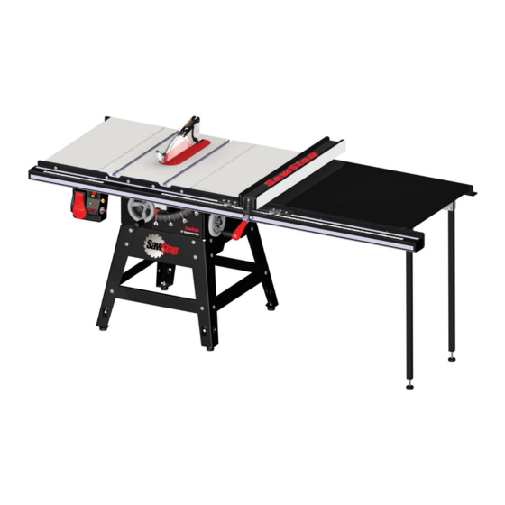
- Page 1 SawStop ® T-Glide Fence System- Professional Series OWNER’S MANUAL...
-
Page 2: Warranty
SawStop will repair the fence system provided it is returned to SawStop, shipping prepaid, within the warranty period. This warranty is void if the fence system is modified without the prior permission of SawStop, LLC, or if the fence system is located or has been used outside of the country where the authorized SawStop distributor from whom the fence system was purchased resides. - Page 3 While unpacking your saw, verify that you have all the components shown below for your specific fence system. The T-Glide Fence System – Professional Series is available in either a 52” system or a 36” system. The components pictured below are from the 52” system, although the components from the 36” system are similar.
- Page 4 Remove six M8 x 25 countersunk socket head bolts from the T-Glide rails hardware pack and insert one through each of the holes in the rail and into the table and extension wings (see Fig.
- Page 5 Repeat this process to level the front edge of the right extension wing. level the extension wing and tighten the nut on this bolt Fig. 5 SawStop T-Glide Fence System - Professional Series PROPRIETARY AND CONFIDENTIAL THE INFORMATION CONTAINED IN THIS...
- Page 6 Notice that the holes in the table are threaded but the holes in the extension wings are not. Remove four M8 x 16 countersunk socket head screws from the T-Glide rails...
- Page 7 52” fence system has two. Locate the support legs, the angle brackets, and Philips Head Screws, the T-Glide table hardware pack. Begin by installing M4 x 16 (12) Foot, the adjustable foot in the bottom of each support leg.
- Page 8 Align the holes in the front and rear rails with the notches in the front and rear edges of the extension table. Fig. 12 SawStop T-Glide Fence System - Professional Series...
- Page 9 5 mm hex key and a 13 mm wrench to fully tighten the nuts on the bolts that mount the extension table to the front rail. straight-edge S a w S to p 10 ” Co nt ra ct or Sa w Fig. 14 SawStop T-Glide Fence System - Professional Series...
- Page 10 Once the foot is in contact with the ground, fully tighten the hex nut against the bottom of the leg using a 13 mm wrench (see Fig. 16). adjust the position of the foot and tighten the hex nut Fig. 16 SawStop T-Glide Fence System - Professional Series...
- Page 11 Installing Your T-Glide Fence System 17. Locate the front tube and the M8 x 16 hex head screws with attached washers from the T-Glide rails hardware pack. Position the tube on the horizontal portion of the front rail with the rulers facing up and the 12 inch ruler on the left side.
- Page 12 (see Fig. 20). Alternatively, if too much force is required to push the fence handle down to clamp the fence to the front tube, you can reduce the clamping pressure by turning both parallelism adjustment screws counter-clockwise. parallelism adjustment screw parallelism adjustment screw Fig. 20 SawStop T-Glide Fence System - Professional Series...
- Page 13 M8 x 16 hex head screws to mount the front tube to the front rail. The fence should now slide smoothly along the front tube without binding and without excessive play. Fig. 22 Congratulations, your fence system is now installed and your saw is ready to use. SawStop T-Glide Fence System - Professional Series...
- Page 14 Using Your T-Glide Fence System The rip fence included with your T-Glide Fence System is used to guide material parallel to the blade when you make rip cuts (cuts that are length-wise along the grain of the wood). The fence must always be used when making rip cuts.
- Page 15 (see Fig. 27). Use a 6 mm hex key to adjust the leveling screws as necessary until the face plate is parallel to the vertical edge of the combination square. Fig. 27 SawStop T-Glide Fence System - Professional Series...
- Page 16 Fig. 29 SawStop T-Glide Fence System - Professional Series...
- Page 17 Tighten the screws to lock the position of the indicator lens. Your fence is now fully adjusted and ready to use. adjust the indicator lens by loosening the two Phillips screws Fig. 31 SawStop T-Glide Fence System - Professional Series...
- Page 18 SawStop T-Glide Fence System - Professional Series...
- Page 19 Rails and Extension Table Parts List for 52” Fence System Description Part No. Qty. Professional 52” T-Glide Fence Rails (items 1-12) TGP-R52A M8x1.25x25 Countersunk Socket Head Bolt TGP-07-001 M8.5x23x2.0 Washer TGP-07-002 M8.2x15.4 Lock Washer TGP-07-003 M8x1.25 Hex Nut TGP-07-004 M8x1.25x16 Countersunk Socket Head Screw TGP-07-005 M8x1.25x16 Hex Head Screw with Attached Washer...
- Page 20 SawStop T-Glide Fence System - Professional Series...
- Page 21 Rails and Extension Table Parts List for 36” Fence System Description Part No. Qty. Professional 36” T-Glide Fence Rails (items 1-12) TGP-R36A M8x1.25x25 Countersunk Socket Head Bolt TGP-07-001 M8.5x23x2.0 Washer TGP-07-002 M8.2x15.4 Lock Washer TGP-07-003 M8x1.25 Hex Nut TGP-07-004 M8x1.25x16 Countersunk Socket Head Screw TGP-07-005 M8x1.25x16 Hex Head Screw (w/ washer)
- Page 22 SawStop T-Glide Fence System - Professional Series...
- Page 23 T-Glide Fence Parts List Description Part No. Qty. Professional T-Glide Rip Fence Assembly (items 1-17) TGP-FA Fence Tube TGP-07-036 Face Plate TGP-07-037 M6x1.0x12 Socket Head Screw TGP-07-038 Handle TGP-07-039 Cam Lock TGP-07-040 M10x1.5x50 Hex Head Bolt TGP-07-041 M10x1.5 Lock Nut...
- Page 24 Service - (503) 582-9934 Fax - (503) 570-3303 Email: info@sawstop.com Updates of this manual may be available at www.sawstop.com. Copyright SawStop, LLC. All Rights Reserved. SawStop is a registered trademark and T-Glide is a trademark of SawStop, LLC. June 2014...
Need help?
Do you have a question about the T-Glide and is the answer not in the manual?
Questions and answers