D-Link DGS-3312SR Release 3.5 Manual
12-port gigabit layer 3 stackable switch
Hide thumbs
Also See for DGS-3312SR Release 3.5:
- Command line interface reference manual (305 pages) ,
- Product manual (244 pages)

Related Manuals for D-Link DGS-3312SR Release 3.5


Summary of Contents for D-Link DGS-3312SR Release 3.5
- Page 1 D-Link™ DGS-3312SR 12-Port Gigabit Layer 3 Stackable Switch Release 3.5 Manual Third Edition (October 2005) Version 0.35 Printed In China RECYCLABLE...
- Page 2 Microsoft Corporation. Other trademarks and trade names may be used in this document to refer to either the entities claiming the marks and names or their products. D-Link Computer Corporation disclaims any proprietary interest in trademarks and trade names other than its own.
-
Page 3: Table Of Contents
DGS-3312SR Stackable Gigabit Layer 3 Switch Table of Contents About This Manual ................................viii Intended Readers ................................viii Typographical Conventions............................viii Notes, Notices, and Cautions..............................ix Safety Instructions................................ix Safety Cautions...................................ix General Precautions for Rack-Mountable Products......................x Protecting Against Electrostatic Discharge ........................xii Introduction....................................1 Switch Description ................................1 Features ....................................1... - Page 4 DGS-3312SR Stackable Gigabit Layer 3 Switch VLAN Setup .................................22 Defining Static Routes..............................22 Web-based User Interface ..............................23 Areas of the User Interface ............................23 Login to Web Manager..............................24 Web Pages and Folders..............................24 Basic Setup..................................25 Switch Information ...............................25 Switch IP Settings.................................25 Security IP Management Stations Configuration......................28 User Account Management ............................28 Admin and User Privileges............................29 Save Changes................................30...
- Page 5 DGS-3312SR Stackable Gigabit Layer 3 Switch IGMP Snooping.................................64 IGMP Snooping Configuration.............................64 Static Router Ports ................................66 Spanning Tree ...................................67 STP Bridge Global Settings............................69 MST Configuration Table.............................71 MSTI Settings................................74 STP Instance Settings ..............................75 STP Port Settings................................77 Forwarding & Filtering ..............................79 Unicast Forwarding ..............................79 Multicast Forwarding ..............................80 VLANs ....................................81 802.1Q Static VLANs..............................85...
- Page 6 DGS-3312SR Stackable Gigabit Layer 3 Switch Static/Default Route Settings ............................119 Static ARP Settings .................................120 RIP....................................121 RIP Global Setting..............................123 RIP Interface Settings ..............................123 OSPF ....................................125 Introduction to OSPF..............................125 OSPF General Setting..............................142 OSPF Area ID Settings...............................142 OSPF Interface Settings..............................144 OSPF Virtual Interface Settings ..........................146 OSPF Area Aggregation Settings ..........................148 OSPF Host Route Settings............................149 DHCP/BOOTP Relay..............................150...
- Page 7 DGS-3312SR Stackable Gigabit Layer 3 Switch Application Authentication Settings...........................177 Authentication Server Group ............................178 Authentication Server Host............................180 Login Method Lists ..............................182 Enable Method Lists ..............................184 Local Enable Password...............................186 Enable Admin ................................187 Management..................................188 User Accounts .................................188 SNMP ....................................190 SNMP Settings ................................190 SNMP User Table...............................191 SNMP View Table..............................193 SNMP Group Table ..............................194 SNMP Community Table ............................196...
- Page 8 DGS-3312SR Stackable Gigabit Layer 3 Switch Traceroute...................................225 Browse IP Address Table ............................226 Browse Routing Table ..............................227 Browse ARP Table ..............................227 Browse IP Multicast Forwarding Table........................228 Browse IGMP Group Table............................228 OSPF Monitor................................229 DVMRP Monitor................................232 PIM Monitor ................................233 Maintenance ..................................234 TFTP Services .................................234 Download Firmware ..............................234 Download Configuration File .............................235 Upload Configuration ..............................235...
-
Page 9: About This Manual
DGS-3312SR Stackable Gigabit Layer 3 Switch About This Manual This manual is divided into ten general sections: Section 1, Introduction - Describes the Switch’s hardware and its features. Section 2, Installation- Helps you get started with the basic installation of the Switch and also describes the front panel, rear panel, side panels, and LED indicators of the Switch. -
Page 10: Notes, Notices, And Cautions
DGS-3312SR Stackable Gigabit Layer 3 Switch Notes, Notices, and Cautions A NOTE indicates important information that helps you make better use of your device. A NOTICE indicates either potential damage to hardware or loss of data and tells you how to avoid the problem. A CAUTION indicates a potential for property damage, personal injury, or death. -
Page 11: General Precautions For Rack-Mountable Products
DGS-3312SR Stackable Gigabit Layer 3 Switch • Do not push any objects into the openings of your system. Doing so can cause fire or electric shock by shorting out interior components. • Use the product only with approved equipment. • Allow the product to cool before removing covers or touching internal components. - Page 12 DGS-3312SR Stackable Gigabit Layer 3 Switch • Systems are considered to be components in a rack. Thus, "component" refers to any system as well as to various peripherals or supporting hardware. CAUTION: Installing systems in a rack without the front and side stabilizers installed could cause the rack to tip over, potentially resulting in bodily injury under certain circumstances.
-
Page 13: Protecting Against Electrostatic Discharge
DGS-3312SR Stackable Gigabit Layer 3 Switch Protecting Against Electrostatic Discharge Static electricity can harm delicate components inside your system. To prevent static damage, discharge static electricity from your body before you touch any of the electronic components, such as the microprocessor. You can do so by periodically touching an unpainted metal surface on the chassis. -
Page 14: Introduction
DGS-3312SR Stackable Gigabit Layer 3 Switch Section 1 Introduction Switch Description Features Front Panel Components LED Indicators Stacking LED Indicators Rear Panel Description Plug-in Modules Switch Stacking Management Options Switch Description The DGS-3312SR is a modular Gigabit Ethernet backbone Switch designed for adaptability and scalability. The Switch provides a management platform and uplink to backbone for a stacked group of up to twelve DES-3226S or DES-3250TG switches in a star topology arrangement. - Page 15 DGS-3312SR Stackable Gigabit Layer 3 Switch • Per-port bandwidth control • Broadcast, Multicast and DLF storm control • IEEE 802.3z and IEEE 802.3x compliant Flow Control for all Gigabit ports • SNMP v.1, v.2, v.3 network management, RMON support • Supports optional external Redundant Power Supply •...
-
Page 16: Front-Panel Components
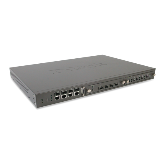
DGS-3312SR Stackable Gigabit Layer 3 Switch Front-Panel Components The front panel of the Switch consists of LED indicators, an RS-232 communication port, two slide-in module slots, and four 1000BASE-T/SFP combo ports. Figure 1- 1. Front Panel View of the Switch as shipped (no modules are installed) Comprehensive LED indicators display the status of the Switch and the network. -
Page 17: Stacking Led Indicators
DGS-3312SR Stackable Gigabit Layer 3 Switch NOTICE: The Stack ID LED on the Switch’s front panel will display an F, regardless of the Switch’s stacking mode (Master Switch in a Switch stack, or Standalone mode). Stacking LED Indicators Stacking LED indicators include the Stack ID indicator on the front panel and the Link/Act indicators on the front of the DEM-540 stacking module. -
Page 18: Rear Panel Description
Connect the optional external redundant power supply to the RPS connector. If the Switch’s internal power unit fails, the redundant power system automatically supplies power to the Switch for uninterrupted operation. The Switch supports the D-Link RPS-200 or RPS-500 redundant power supply units. Plug-in Modules The DGS-3312SR Switch is able to accommodate optional plug-in modules in order to increase functionality and performance. - Page 19 DGS-3312SR Stackable Gigabit Layer 3 Switch DEM-340MG SFP (Mini GBIC) Module Figure 1- 6. Four-port Gigabit SFP module • Front-panel module • Connects to Gigabit Ethernet devices • May be used as stacking ports for DES-3250TG slave switches. • LED indicators for Link/Activity and Status DEM-540 IEEE 1394 Stacking Module Figure 1- 7.
-
Page 20: Switch Stacking
DGS-3312SR Stackable Gigabit Layer 3 Switch Switch Stacking The DGS-3312SR can be stacked with a DES-3226S or DES-3250TG, functioning as the Master of the stack. There are three connection options available to for stacking. 1. Utilizing a gigabit Ethernet port with either the built-in combination mini-GBIC ports or using the DEM-340T 1000BASE-T stacking module. -
Page 21: Management Options
RFC 2575 SNMP View-based ACM MIB • RFC 2674 802.1p and 802.1q Bridge MIB • RFC 2737 Entity MIB • RFC 2932 IPMROUTE STD MIB • RFC 2933 IGMP MIB • RFC 2934 PIM MIB • IEEE8021-PAE 802.1x PAE MIB • D-Link Enterprise MIB... -
Page 22: Installation
DGS-3312SR Stackable Gigabit Layer 3 Switch SECTION 2 Installation Package Contents Before You Connect to the Network Installing the Switch without a Rack Installing the Switch in a Rack Connecting Stacked Switch Groups Configuring a Switch Group for Stacking External Redundant Power System Connecting the Console Port Password Protection SNMP Settings... -
Page 23: Installing The Switch Without The Rack
DGS-3312SR Stackable Gigabit Layer 3 Switch Installing the Switch without the Rack The Switch is supplied with rubber feet for stationing it on a flat surface and mounting brackets and screws for mounting the Switch in a rack. 1. Install the Switch on a level surface that can safely support the weight of the Switch and its attached cables. The Switch must have adequate space for ventilation and for accessing cable connectors. -
Page 24: Mounting The Switch In A Standard 19" Rack
DGS-3312SR Stackable Gigabit Layer 3 Switch Mounting the Switch in a Standard 19" Rack Figure 2-3. Install Switch in equipment rack... -
Page 25: Connecting Stacked Switch Groups
DGS-3312SR Stackable Gigabit Layer 3 Switch Connecting Stacked Switch Groups The DGS-3312SR has the capability to hold twelve gigabit ports that may be used in standalone mode or can be used in a stacking configuration to provide up to 576 10/100 Mbps ports and 12 Gigabit ports in a star architecture. For stacking, the DGS-3312SR will be the master switch of a stack of DES-3226S switches, DES-3250TG switches or a combination of both. -
Page 26: Configuring A Switch Group For Stacking
DGS-3312SR Stackable Gigabit Layer 3 Switch Configuring a Switch Group for Stacking Follow the instructions below to first configure the slave units, and then to configure the DGS-3312SR as the designated Master. NOTICE: The DGS-3312SR can be used to manage a Switch stack consisting of only DES-3226S and/or DES-3250TG Switches. - Page 27 DGS-3312SR Stackable Gigabit Layer 3 Switch DGS-3312SR:4#config stacking mode enable Command: config stacking mode enable The new stacking mode configuration must be saved and the system restarted to put the new settings into effect. If you do not save the changes now, they will be lost. Saving all configurations to NV-RAM...
-
Page 28: External Redundant Power System
DGS-3312SR Stackable Gigabit Layer 3 Switch External Redundant Power System The Switch supports an external redundant power system. Figure 2-8. DPS-200 with DGS-3312SR NOTE: See the DPS-200 documentation for more information. CAUTION: Do not use the Switch with any redundant power system other than the DPS-200. -
Page 29: Connecting The Console Port
DGS-3312SR Stackable Gigabit Layer 3 Switch Connecting the Console Port The Switch provides an RS-232 serial port that enables a connection to a computer or terminal for monitoring and configuring the Switch. This port is a male DB-9 connector, implemented as a data terminal equipment (DTE) connection. To use the console port, you need the following equipment: •... - Page 30 DGS-3312SR Stackable Gigabit Layer 3 Switch 1. At the CLI login prompt, enter create account admin followed by the <user name> and press the Enter key. 2. You will be asked to provide a password. Type the <password> used for the administrator account being created and press the Enter key.
-
Page 31: Snmp Settings
DGS-3312SR Stackable Gigabit Layer 3 Switch SNMP Settings Simple Network Management Protocol (SNMP) is an OSI Layer 7 (Application Layer) designed specifically for managing and monitoring network devices. SNMP enables network management stations to read and modify the settings of gateways, routers, Switches, and other network devices. -
Page 32: Ip Address Assignment
DGS-3312SR Stackable Gigabit Layer 3 Switch IP Address Assignment Each Switch must be assigned its own IP Address, which is used for communication with an SNMP network manager or other TCP/IP application (for example BOOTP, TFTP). The Switch’s default IP address is 10.90.90.90. You can change the default Switch IP address to meet the specification of your networking address scheme. -
Page 33: Connecting Devices To The Switch
DGS-3312SR Stackable Gigabit Layer 3 Switch Figure 2-10. Assigning the Switch an IP Address In the above example, the Switch was assigned an IP address of 10.22.24.9 with a subnet mask of 255.0.0.0. The system message Success indicates that the command was executed successfully. The Switch can now be configured and managed via Telnet and the CLI or via the Web-based management. -
Page 34: Basic Switch Management
DGS-3312SR Stackable Gigabit Layer 3 Switch Section 3 Basic Switch Management Before You Start General Deployment Strategy Web-based User Interface Basic Setup Switch Information Switch IP Settings Security IP Management Stations User Accounts Management Saving Changes Factory Reset Restart System Advanced Settings Switch Stack Management All software function of the DGS-3312SR can managed, configured and monitored via the embedded web-based (HTML) -
Page 35: Vlan Setup
DGS-3312SR Stackable Gigabit Layer 3 Switch 3. Determine which network resources must be shared by the subnets. Shared resources may be connected directly to Layer 3 Switches. Static routes to each of the shared resources should be determined. 4. Determine how each subnet will communicate with the WAN or Internet. Again, static routes should be determined and default gateways identified. -
Page 36: Web-Based User Interface
DGS-3312SR Stackable Gigabit Layer 3 Switch Web-based User Interface The user interface provides access to various Switch configuration and management screens, allows you to view performance statistics, and permits you to graphically monitor the system status. Areas of the User Interface The figure below shows the user interface. -
Page 37: Login To Web Manager
DGS-3312SR Stackable Gigabit Layer 3 Switch Login to Web Manager To begin managing the Switch simply run the browser you have installed on your computer and point it to the IP address you have defined for the device. The URL in the address bar should read something like: http://123.123.123.123, where the numbers 123 represent the IP address of the Switch. -
Page 38: Basic Setup
DGS-3312SR Stackable Gigabit Layer 3 Switch Basic Setup The subsections below describe how to change some of the basic settings for the Switch such as changing IP settings and assigning user names and passwords for management access privileges, as well as how to save the changes and restart the Switch. - Page 39 DGS-3312SR Stackable Gigabit Layer 3 Switch Figure 3-3. Switch IP Settings window NOTE: The Switch’s factory default IP address is 10.90.90.90 with a subnet mask of 255.0.0.0 and a default gateway of 0.0.0.0. To manually assign the Switch’s IP address, subnet mask, and default gateway address: •...
- Page 40 DGS-3312SR Stackable Gigabit Layer 3 Switch Subnet Mask A Bitmask that determines the extent of the subnet that the Switch is on. Should be of the form xxx.xxx.xxx.xxx, where each xxx is a number (represented in decimal) between 0 and 255. The value should be 255.0.0.0 for a Class A network, 255.255.0.0 for a Class B network, and 255.255.255.0 for a Class C network, but custom subnet masks are allowed.
-
Page 41: Security Ip Management Stations Configuration
DGS-3312SR Stackable Gigabit Layer 3 Switch Security IP Management Stations Configuration Use the Security IP Management window to define up to four community strings. Community strings are used to verify who can receive SNMP information from the Switch. To access the Security IP Management window, click Trusted Host in the Security folder. Figure 3-4. -
Page 42: Admin And User Privileges
DGS-3312SR Stackable Gigabit Layer 3 Switch To modify or delete an existing user, click on the Modify button for that user. Figure 3- 7. User Account Modify Table window Modify or delete an existing user account in the User Account Modify Table window. To delete the user account, click on the Delete button. -
Page 43: Save Changes
DGS-3312SR Stackable Gigabit Layer 3 Switch Save Changes Changes made to the Switch’s configuration must be saved in order to retain them. Access the Save Configuration window by clicking the Save Changes button located in the Maintenance folder. Figure 3- 8. Save Configuration window The Switch has two levels of memory, normal RAM and non-volatile or NV-RAM. -
Page 44: Restart System
DGS-3312SR Stackable Gigabit Layer 3 Switch • Reset Config − Returns all configuration settings to the factory default settings except the stacking mode configuration, but does not save the settings or reboot the Switch. If you select this option the Switch configuration will be returned to the factory default settings for the current session only. -
Page 45: Advanced Settings
DGS-3312SR Stackable Gigabit Layer 3 Switch Advanced Settings To view the following window, click Configuration > Advanced Settings: Figure 3- 11. Switch Information (Advanced Settings) window The Advanced Settings options are summarized in the table below: Parameter Description Serial Port Auto Select the logout time used for the console interface. - Page 46 DGS-3312SR Stackable Gigabit Layer 3 Switch Multicast router Only If this option is enabled and IGMP Snooping is also enabled, the Switch forwards all multicast traffic to a multicast-enabled router only. Otherwise, the Switch will forward all multicast traffic to any IP router. Telnet Status Telnet configuration is Enabled by default.
-
Page 47: Switch Stack Management
DGS-3312SR Stackable Gigabit Layer 3 Switch Switch Stack Management The DGS-3312SR has a possible twelve gigabit ports that may be used in standalone mode or can be used in a stacking configuration to provide up to 576 10/100 Mbps ports and 12 Gigabit ports in a star architecture. For stacking, the DGS- 3312SR will be the master switch of a stack of DES-3226S switches, DES-3250TG switches or a combination of both. - Page 48 DGS-3312SR Stackable Gigabit Layer 3 Switch Figure 3- 13. Stack Mode Setup (stacking enabled) window Variables in this window are described below: Parameter Description Displays the Switch’s order in the stack. The Switch with a unit ID of 15 is the master Switch.
- Page 49 DGS-3312SR Stackable Gigabit Layer 3 Switch Figure 3- 14. Stack Information web page with updated stack configuration...
-
Page 50: Basic Configuration
DGS-3312SR Stackable Gigabit Layer 3 Switch Section 4 Basic Configuration Switch Information IP Address Advanced Settings Port Configuration Port Description Port Mirroring Traffic Control Link Aggregation Port Access Entity IGMP Snooping Spanning Tree Forwarding & Filtering VLANs MAC Notification Port Security Configuration System Log Server SNTP Settings Access Profile Table... -
Page 51: Switch Information
DGS-3312SR Stackable Gigabit Layer 3 Switch Switch Information The first page displayed upon logging in is the System Information (Basic Settings) window. This window can be accessed at any time by clicking the Switch Information link in the Configuration folder. Figure 4- 1. - Page 52 DGS-3312SR Stackable Gigabit Layer 3 Switch NOTE: The Switch’s factory default IP address is 10.90.90.90 with a subnet mask of 255.0.0.0 and a default gateway of 0.0.0.0. To manually assign the Switch’s IP address, subnet mask, and default gateway address: •...
- Page 53 DGS-3312SR Stackable Gigabit Layer 3 Switch This allows the entry of a VLAN ID from which a management station will be allowed to manage the Switch using TCP/IP (in-band via web manager or Telnet). Management stations that are on VLANs other than the one entered in the VID field will not be able to manage the Switch in-band unless their IP addresses are entered in the Security IP Management window.
-
Page 54: Advanced Settings
DGS-3312SR Stackable Gigabit Layer 3 Switch Advanced Settings To view the following window, click Configuration > Advanced Settings: Figure 4- 3. Switch Information (Advanced Settings) window The Advanced Settings options are summarized in the table below: Parameter Description Serial Port Auto Select the logout time used for the console interface. - Page 55 DGS-3312SR Stackable Gigabit Layer 3 Switch Multicast router Only If this option is enabled and IGMP Snooping is also enabled, the Switch forwards all multicast traffic to a multicast-enabled router only. Otherwise, the Switch will forward all multicast traffic to any IP router. Telnet Status Telnet configuration is Enabled by default.
-
Page 56: Port Configuration
DGS-3312SR Stackable Gigabit Layer 3 Switch Port Configuration To configure basic port settings such as port speed, duplex, and learning state, use the Port Configuration window. Click the Port Configuration link in the Configuration folder: Figure 4- 4. Port Configuration and The Port Information Table window To configure Switch ports: Choose the Unit from the pull-down menu. - Page 57 DGS-3312SR Stackable Gigabit Layer 3 Switch The Switch allows the user to configure two types of gigabit connections; 1000M/Full_M and 1000M/Full_S. Gigabit connections are only supported in full duplex connections and take on certain characteristics that are different from the other choices listed.
-
Page 58: Port Description
DGS-3312SR Stackable Gigabit Layer 3 Switch Port Description The Switch supports a port description feature where the user may name various ports on the Switch. To assign names or descriptions to various ports, click Port Description on the Configuration folder: Figure 4- 5. -
Page 59: Port Mirroring
DGS-3312SR Stackable Gigabit Layer 3 Switch Port Mirroring The Switch allows you to copy frames transmitted and received on a port and redirect the copies to another port. You can attach a monitoring device to the mirrored port, such as a sniffer or an RMON probe, to view details about the packets passing through the first port. -
Page 60: Traffic Control
DGS-3312SR Stackable Gigabit Layer 3 Switch Traffic Control Use the Traffic Control Setting window to enable or disable storm control and adjust the threshold for multicast and broadcast storms, as well as DLF (Destination Look Up Failure). Traffic control settings are applied to individual Switch modules. -
Page 61: Link Aggregation
DGS-3312SR Stackable Gigabit Layer 3 Switch Link Aggregation Understanding Port Trunk Groups Port trunk groups are used to combine a number of ports together to make a single high-bandwidth data pipeline. The DGS-3312SR supports up to six port trunk groups with two to eight ports in each group. A potential bit rate of 8000 Mbps can be achieved. - Page 62 DGS-3312SR Stackable Gigabit Layer 3 Switch To configure port trunking, click on the Link Aggregation hyperlink in the Configuration folder and then click Link Aggregation: Figure 4- 9. Port Trunking group window To configure port trunk groups, click the Add button to add a new trunk group and then use the Port Trunking Configuration window below to set up trunk groups.
-
Page 63: Lacp Port Settings
DGS-3312SR Stackable Gigabit Layer 3 Switch LACP Port Settings The LACP Port Mode Setup window is used in conjunction with the Link Aggregation windows to create port trunking groups on the Switch. Using the following window, the user may set which ports will be active and passive in processing and sending LACP control frames. -
Page 64: Port Access Entity (802.1X)
DGS-3312SR Stackable Gigabit Layer 3 Switch Port Access Entity (802.1X) 802.1x Port-Based and MAC-Based Access Control The IEEE 802.1x standard is a security measure for authorizing and authenticating users to gain access to various wired or wireless devices on a specified Local Area Network by using a Client and Server based access control model. This is accomplished by using a RADIUS server to authenticate users trying to access a network by relaying Extensible Authentication Protocol over LAN (EAPOL) packets between the Client and the Server. -
Page 65: Authentication Server
DGS-3312SR Stackable Gigabit Layer 3 Switch Authentication Server The Authentication Server is a remote device that must be running a RADIUS Server program and must be configured properly on the Authenticator (Switch). Clients connected to a port on the Switch must be authenticated by the Authentication Server (RADIUS) before attaining any services offered by the Switch on the LAN. -
Page 66: Client
DGS-3312SR Stackable Gigabit Layer 3 Switch Client The Client is simply the end station that wishes to gain access to the LAN or switch services. All end stations must be running software that is compliant with the 802.1x protocol. For users running Windows XP, that software is included within the operating system. - Page 67 DGS-3312SR Stackable Gigabit Layer 3 Switch The D-Link implementation of 802.1x allows network administrators to choose between two types of Access Control used on the Switch, which are: 1. Port-Based Access Control – This method requires only one user to be authenticated per port by a remote RADIUS server to allow the remaining users on the same port access to the network.
- Page 68 DGS-3312SR Stackable Gigabit Layer 3 Switch MAC-Based Network Access Control RADIUS Server Ethernet Switch … 802.1X 802.1X 802.1X 802.1X 802.1X 802.1X 802.1X 802.1X 802.1X 802.1X 802.1X 802.1X Client Client Client Client Client Client Client Client Client Client Client Client Network access controlled port Network access uncontrolled port Figure 4- 19.
-
Page 69: 802.1X Authenticator Settings
DGS-3312SR Stackable Gigabit Layer 3 Switch 802.1X Authenticator Settings To display the current 802.1X Authenticator Settings on the Switch, click Configuration > Port Access Entity > 802.1x Authenticator Settings, which will display the following window. Figure 4- 20. 1 802.1X Authenticator Settings window To configure the 802.1X Authenticator settings for a given port, click on the blue port number link under the Port heading. - Page 70 DGS-3312SR Stackable Gigabit Layer 3 Switch The following Authenticator Settings parameters can be set: Parameter Description Allows you to specify a Switch in a Switch stack using that Switch’s Unit ID. The Unit number 15 indicates a Switch in standalone mode. From/To A consecutive group of ports may be configured starting with the selected port.
-
Page 71: Pae System Control
DGS-3312SR Stackable Gigabit Layer 3 Switch PAE System Control To set the port authenticating settings, open the Port Access Entity folder, and then the PAE System Control folder. Finally, click on the 802.1X Capability Settings link. 802.1X Capability Settings The following window will allow the user to set the Capability settings for the Switch on a per port basis. This window can be viewed by clicking Configuration >... - Page 72 DGS-3312SR Stackable Gigabit Layer 3 Switch Initializing Ports for Port-Based 802.1x Existing 802.1x port and MAC settings are displayed and can be configured using the window below. Click Configuration > Port Access Entity > PAE System Control > Initialize Port(s) to open the following window: Figure 4- 23.
-
Page 73: Initializing Ports For Mac Based 802.1X
DGS-3312SR Stackable Gigabit Layer 3 Switch Initializing Ports for MAC Based 802.1x To initialize ports for the MAC side of 802.1x, the user must first enable 802.1x by MAC address in the Advanced Settings window. Click Configuration > Port Access Entity > PAE System Control > Initialize Port(s) to open the following window: Figure 4- 24. -
Page 74: Reauthenticate Port(S) For Port Based 802.1X
DGS-3312SR Stackable Gigabit Layer 3 Switch Reauthenticate Port(s) for Port Based 802.1x This window allows you to reauthenticate a port or group of ports by choosing a port or group of ports by using the pull down menus From and To and clicking Apply. The Reauthenticate Port Table displays the current status of the reauthenticated port(s) once you have clicked Apply. -
Page 75: Reauthenticate Port(S) For Mac-Based 802.1X
DGS-3312SR Stackable Gigabit Layer 3 Switch Reauthenticate Port(s) for MAC-based 802.1x To reauthenticate ports for the MAC side of 802.1x, the user must first enable 802.1x by MAC address in the Advanced Settings window. Click Configuration > Port Access Entity > PAE System Control > Reauthenticate Port(s) to open the following window: Figure 4- 26. -
Page 76: Radius Server
DGS-3312SR Stackable Gigabit Layer 3 Switch RADIUS Server The RADIUS feature of the Switch allows you to facilitate centralized user administration as well as providing protection against a sniffing, active hacker. RADIUS Server Click the RADIUS Server link in the RADIUS Server folder under Port Access Entity. Figure 4- 27. -
Page 77: Igmp Snooping
DGS-3312SR Stackable Gigabit Layer 3 Switch IGMP Snooping In order to use IGMP Snooping it must first be enabled for the entire Switch (see Advanced Settings). You may then fine- tune the settings for each VLAN using the IGMP Snooping Settings window. When enabled for IGMP snooping, the Switch can open or close a port to a specific Multicast group member based on IGMP messages sent from the device to the IGMP host or vice versa. - Page 78 DGS-3312SR Stackable Gigabit Layer 3 Switch Parameter Description VLAN ID The VLAN ID number. VLAN Name The VLAN name. Query Interval The Query Interval field is used to set the time (in seconds) between transmitting IGMP queries. Entries between 1 and 65535 seconds are allowed. The default value is 125.
-
Page 79: Static Router Ports
DGS-3312SR Stackable Gigabit Layer 3 Switch Static Router Ports A static router port is a port that has a multicast router attached to it. Generally, this router would have a connection to a WAN or to the Internet. Establishing a router port will allow multicast packets coming from the router to be propagated through the network, as well as allowing multicast messages (IGMP) coming from the network to be propagated to the router. -
Page 80: Spanning Tree
802.1d STP will be familiar to most networking professionals. However, since 802.1w RSTP and 802.1s MSTP has been recently introduced to D-Link managed Ethernet switches, a brief introduction to the technology is provided below followed by a description of how to set up 802.1d STP, 802.1w RSTP and 802.1s MSTP. -
Page 81: Edge Port
DGS-3312SR Stackable Gigabit Layer 3 Switch transition states disabled, blocking and listening used in 802.1d and creates a single state Discarding. In either case, ports do not forward packets. In the STP port transition states disabled, blocking or listening or in the RSTP/MSTP port state discarding, there is no functional difference, the port is not active in the network topology. -
Page 82: Stp Bridge Global Settings
DGS-3312SR Stackable Gigabit Layer 3 Switch STP Bridge Global Settings To open the following window, open the Spanning Tree folder in the Configuration menu and click the STP Bridge Global Settings link. Figure 4- 32. STP Bridge Global Settings – STP compatible Figure 4- 33. - Page 83 DGS-3312SR Stackable Gigabit Layer 3 Switch The following parameters can be set: Parameter Description STP Status Use the pull-down menu to enable or disable STP globally on the Switch. The default is Disabled. STP Version Use the pull-down menu to choose the desired version of STP to be implemented on the Switch.
-
Page 84: Mst Configuration Table
DGS-3312SR Stackable Gigabit Layer 3 Switch MST Configuration Table The following screens in the MST Configuration Table window allow the user to configure a MSTI instance on the Switch. These settings will uniquely identify a multiple spanning tree instance set on the Switch. The Switch initially possesses one CIST or Common Internal Spanning Tree of which the user may modify the parameters for but cannot change the MSTI ID for, and cannot be deleted. - Page 85 DGS-3312SR Stackable Gigabit Layer 3 Switch Figure 4- 36. Instance ID Settings window- Add The user may configure the following parameters to create a MSTI in the Switch. Parameter Description MSTI ID Enter a number between 1 and 15 to set a new MSTI on the Switch. Type Create is selected to create a new MSTI.
- Page 86 DGS-3312SR Stackable Gigabit Layer 3 Switch Click Apply to implement changes made. To configure the parameters for a previously set MSTI, click on its hyperlinked MSTI ID number, which will reveal the following screen for configuration. Figure 4- 38. Instance ID Settings window - Modify The user may configure the following parameters for a MSTI on the Switch.
-
Page 87: Msti Settings
DGS-3312SR Stackable Gigabit Layer 3 Switch MSTI Settings This window displays the current MSTI configuration settings and can be used to update the port configuration for an MSTI ID. If a loop occurs, the MSTP function will use the port priority to select an interface to put into the forwarding state. -
Page 88: Stp Instance Settings
DGS-3312SR Stackable Gigabit Layer 3 Switch STP Instance Settings The following window displays MSTIs currently set on the Switch. To view the following table, click Configuration > Spanning Tree > STP Instance Settings: Figure 4- 41. STP Instance Settings The following information is displayed: Parameter Description Instance Type... - Page 89 DGS-3312SR Stackable Gigabit Layer 3 Switch The following parameters may be viewed in the STP Instance Operational Status windows: Parameter Description Designated Root This field will show the priority and MAC address of the Root Bridge. Bridge External Root Cost This defines a metric that indicates the relative cost of forwarding packets to the specified port list.
-
Page 90: Stp Port Settings
DGS-3312SR Stackable Gigabit Layer 3 Switch STP Port Settings STP can be set up on a port per port basis. To view the following window click Configuration > Spanning Tree > STP Port Settings: Figure 4- 44. STP Port Settings and Table window In addition to setting Spanning Tree parameters for use on the Switch level, the Switch allows for the configuration of groups of ports, each port-group of which will have its own spanning tree, and will require some of its own configuration settings. - Page 91 DGS-3312SR Stackable Gigabit Layer 3 Switch Hello Time The time interval between the transmission of configuration messages by the des- ignated port, to other devices on the bridged LAN, thus stating that the Switch is still functioning. The user may choose a time between 1 and 10 seconds. The default is 2 seconds.
-
Page 92: Forwarding & Filtering
DGS-3312SR Stackable Gigabit Layer 3 Switch Forwarding & Filtering The Switch allows permanent or static entries into the forwarding database (FDB). These FDB entries are MAC addresses that will not age out. In addition, multicast forwarding may be customized to conform to rules for the different ports by setting up multicast filter modes for each port. -
Page 93: Multicast Forwarding
DGS-3312SR Stackable Gigabit Layer 3 Switch Multicast Forwarding The following figure and table describe how to set up Multicast forwarding on the Switch. Open the Forwarding & Filtering folder and click on the Multicast Forwarding link to see the entry window below: Figure 4- 46. -
Page 94: Vlans
DGS-3312SR Stackable Gigabit Layer 3 Switch VLANs The Switch Web Manager’s VLANs sub-folder is divided into two main windows, 802.1Q Static VLANs and 802.1Q Port Settings. Each is described after a short overview of VLANs. VLANs can function somewhat differently in a Layer 3 Switch, that is when the VLANs are Layer 3-based, than if they are strictly based on Layer 2 information. -
Page 95: Q Vlan Packet Forwarding
DGS-3312SR Stackable Gigabit Layer 3 Switch IEEE 802.1Q VLANs Some relevant terms: • Tagging - The act of putting 802.1Q VLAN information into the header of a packet. • Untagging - The act of stripping 802.1Q VLAN information out of the packet header. •... -
Page 96: Port Vlan Id
DGS-3312SR Stackable Gigabit Layer 3 Switch Figure 4- 49. IEEE 802.1Q Tag The EtherType and VLAN ID are inserted after the MAC source address, but before the original EtherType/Length or Logical Link Control. Because the packet is now a bit longer than it was originally, the Cyclic Redundancy Check (CRC) must be recalculated. -
Page 97: Tagging And Untagging
DGS-3312SR Stackable Gigabit Layer 3 Switch Tag-aware Switches must keep a table to relate PVIDs within the Switch to VIDs on the network. The Switch will compare the VID of a packet to be transmitted to the VID of the port that is to transmit the packet. If the two VIDs are different, the Switch will drop the packet. -
Page 98: 802.1Q Static Vlans
DGS-3312SR Stackable Gigabit Layer 3 Switch 802.1Q Static VLANs To create or modify an 802.1Q VLAN: In the Configuration folder, open the VLANs folder and click the Static VLAN Entry link to open the following window: Figure 4- 51. 802.1Q Static VLANs and Current 802.1Q Static VLAN Entries window The first 802.1Q Static VLANs window lists all previously configured VLANs by VLAN ID and name. - Page 99 DGS-3312SR Stackable Gigabit Layer 3 Switch Parameter Description Unit Choose the Switch on which the VLAN will be created. VID (VLAN ID) For a new VLAN entry, type in a unique identifier. This number is used to configure other settings such as GVRP status for ports in the VLAN. Auto Assign –...
- Page 100 DGS-3312SR Stackable Gigabit Layer 3 Switch Figure 4- 54. 802.1Q Static VLANs With Added VLAN window To change the port settings of any listed VLAN, click the Modify button. Now click the Modify button in the first 802.1Q Static VLANs window for the newly created VLAN (engineering). A new window appears, use this to configure the port settings to the existing VLAN, exactly as in the Add New VLAN window.
-
Page 101: Gvrp Settings
DGS-3312SR Stackable Gigabit Layer 3 Switch GVRP Settings Open the GVRP Settings window and select the Unit and range of ports to configure. For the selected port or group of ports, choose to enable or disable Ingress checking and establish an acceptable packet rule. Ingress Checking is used to limit traffic by filtering incoming packets that have a PVID does not match the PVID of the port. -
Page 102: Qos
DGS-3312SR Stackable Gigabit Layer 3 Switch The DGS-3312SR supports 802.1p priority queuing Quality of Service. The following section discusses the implementation of QoS (Quality of Service) and benefits of using 802.1p priority queuing. The Advantages of QoS QoS is an implementation of the IEEE 802.1p standard that allows network administrators a method of reserving bandwidth for important functions that require a large bandwidth or have a high priority, such as VoIP (voice-over Internet Protocol), web browsing applications, file server applications or video conferencing. -
Page 103: Understanding Qos
DGS-3312SR Stackable Gigabit Layer 3 Switch Understanding QoS The Switch has nine priority classes of service, one of which is internal and not configurable. These priority classes of service are labeled as 7, the high class to 0, the lowest class. The eight priority tags, specified in IEEE 802.1p are mapped to the Switch's priority classes of service as follows: Priority 0 is assigned to the Switch's Q2 class. -
Page 104: 802.1P Default Priority
DGS-3312SR Stackable Gigabit Layer 3 Switch 802.1p Default Priority The Switch allows the assignment of a default 802.1p priority to each port on the Switch. Click on the 802.1p Default Priority link in the QoS sub-folder: Figure 4- 58. Port Default Priority assignment and The Port Priority Table window This page allows you to assign a default 802.1p priority to any given port on the Switch. -
Page 105: Qos Output Scheduling Configuration
DGS-3312SR Stackable Gigabit Layer 3 Switch QoS Output Scheduling Configuration QoS can be customized by changing the output scheduling used for the hardware queues in the Switch. As with any changes to QoS implementation, careful consideration should be given to how network traffic in lower priority queues are affected. -
Page 106: Traffic Segmentation
DGS-3312SR Stackable Gigabit Layer 3 Switch Traffic Segmentation Traffic segmentation is used to limit traffic flow from a single port to a group of ports on either a single Switch (in standalone mode) or a group of ports on another Switch in a Switch stack. This method of segmenting the flow of traffic is similar to using VLANs to limit traffic, but is more restrictive. -
Page 107: Port Bandwidth
DGS-3312SR Stackable Gigabit Layer 3 Switch Port Bandwidth The bandwidth control settings are used to place a ceiling on the transmitting and receiving data rates for any selected port. Figure 4- 62. Bandwidth Settings window The following parameters can be set or are displayed: Parameter Description Unit... -
Page 108: Mac Notification
DGS-3312SR Stackable Gigabit Layer 3 Switch MAC Notification MAC address notification is used to monitor MAC addresses as they are learned and entered into the Switch’s MAC forwarding database. MAC Notification Global Settings The following window will allow the user to globally enable MAC Notification on the Switch. -
Page 109: Port Security Configuration
DGS-3312SR Stackable Gigabit Layer 3 Switch Port Security Configuration The following three windows will allow the user to implement security functions on a per port basis on the Switch or a switch in a switch stack. To access the following windows, open the Port Security Configuration folder in the Configuration folder. -
Page 110: Port Lock Entry Delete
DGS-3312SR Stackable Gigabit Layer 3 Switch Port Lock Entry Delete The Port Lock Entry Delete window is used to remove an entry from the port security entries learned by the Switch and entered into the forwarding database. To view the following window, click Configuration > Port Security Configuration >... -
Page 111: System Log Server
DGS-3312SR Stackable Gigabit Layer 3 Switch System Log Server Use the System Log to keep a record of warning and other pertinent system information. The Switch can send system log (SysLog) messages to up to four designated servers, which can be set on the Switch utilizing the System Log Servers window. - Page 112 DGS-3312SR Stackable Gigabit Layer 3 Switch security/authorization messages messages generated internally by syslog line printer subsystem network news subsystem UUCP subsystem clock daemon security/authorization messages FTP daemon NTP subsystem log audit log alert clock daemon local use 0 (local0) local use 1 (local1) local use 2 (local2) local use 3 (local3) local use 4 (local4)
-
Page 113: Sntp Settings
DGS-3312SR Stackable Gigabit Layer 3 Switch SNTP Settings The Simple Network Time Protocol (SNTP) (an adaptation of the Network Time Protocol (NTP)) is configured on the Switch using the following windows. Time Setting The following window will allow the user to configure the time settings for the Switch and can be accessed by clicking Configuration >... -
Page 114: Time Zone And Dst Settings
DGS-3312SR Stackable Gigabit Layer 3 Switch Time Zone and DST Settings The following window is used to set up Time Zone and Daylight Savings configurations for the Switch and can be accessed by clicking Configuration > SNTP Settings > Time Zone and DST. Figure 4- 71. - Page 115 DGS-3312SR Stackable Gigabit Layer 3 Switch Repeating - Using repeating mode will enable DST seasonal time adjustment. Repeating mode requires that the DST beginning and ending date be specified using DST Repeating Settings a formula. For example, specify to begin DST on Saturday during the second week of April and end DST on Sunday during the last week of October.
-
Page 116: Access Profile Table
DGS-3312SR Stackable Gigabit Layer 3 Switch Access Profile Table Access profiles allow you to establish criteria to determine whether or not the Switch will forward packets based on the information contained in each packet’s header. These criteria can be specified on a basis of VLAN, MAC address or IP address. - Page 117 DGS-3312SR Stackable Gigabit Layer 3 Switch Parameter Description Type in a unique identifier number for this profile set. This value can be set from 1 to Profile ID (1-255) 255. Type Select profile based on Ethernet (MAC Address), IP address or packet content mask. This will change the menu according to the requirements for the type of profile.
- Page 118 DGS-3312SR Stackable Gigabit Layer 3 Switch The following parameters can be set: Parameter Description Type in a unique identifier number for this profile set. This value can be set from 1 to Profile ID (1-255) 255. Select profile based on Ethernet (MAC Address), IP address, packet content mask or IPv6.
- Page 119 DGS-3312SR Stackable Gigabit Layer 3 Switch The window shown below is the Access Profile Configuration window for Packet Content Mask. Figure 4- 75. Access Profile Configuration (Packet Content Mask) window This window will aid the user in configuring the Switch to mask packet headers beginning with the offset value specified. The following fields are used to configure the Packet Content Mask window: The following parameters can be set: Parameter...
- Page 120 DGS-3312SR Stackable Gigabit Layer 3 Switch The user may set the Access Profile Table window on a per-port basis by entering a port Port number in this field. Entering “all” will denote all ports on the Switch. To establish the rule for a previously created Access Profile, select the Access Profile entry from the Access Profile Table window and then click the Modify button for that individual entry.
- Page 121 DGS-3312SR Stackable Gigabit Layer 3 Switch Type Selected profile based on Ethernet (MAC Address), IP address or packet content mask. This will change the menu according to the requirements for the type of profile. Ethernet instructs the Switch to examine the layer 2 part of each packet •...
- Page 122 DGS-3312SR Stackable Gigabit Layer 3 Switch Figure 4- 78. Access Rule Configuration (IP) window The following parameters can be set: Parameter Description This is the identifier number for this profile set. Profile ID Mode Select Permit to specify that the packets that match the access profile are forwarded by the Switch, according to any additional rule added (see below).
- Page 123 DGS-3312SR Stackable Gigabit Layer 3 Switch Replace DSCP (0- Select this option to instruct the Switch to replace the DSCP value (in a packet that meets the selected criteria) with the value entered in the adjacent field. Allows the entry of a name for a previously configured VLAN. VLAN Name Source IP Source IP Address - Enter an IP Address mask for the source IP address.
- Page 124 DGS-3312SR Stackable Gigabit Layer 3 Switch Access ID Type in a unique identifier number for this access. This value can be set from 1 to 255. Selected profile based on Ethernet (MAC Address), IP address or packet content Type mask. This will change the menu according to the requirements for the type of profile. Ethernet instructs the Switch to examine the layer 2 part of each packet •...
-
Page 125: Layer 3 Ip Networking
DGS-3312SR Stackable Gigabit Layer 3 Switch Section 5 Layer 3 IP Networking L3 Global Advanced Settings IP Interface Settings MD5 Key Settings Route Redistribution Settings Static/Default Route Settings Static ARP Settings OSPF DHCP/BOOTP Relay DNS Relay VRRP IP Multicast L3 Global Advanced Settings In order to use DVMRP, PIM-DM, RIP, or OSPF, the Switch must first be globally enabled for Layer 3 IP Networking. -
Page 126: Ip Interface Settings
DGS-3312SR Stackable Gigabit Layer 3 Switch IP Interfaces Settings and IP Multinetting IP Multinetting is a function that allows multiple IP interfaces to be assigned to the same VLAN. This is beneficial to the administrator when the number of IPs on the original interface is insufficient and the network administrator wishes not to resize the interface. - Page 127 DGS-3312SR Stackable Gigabit Layer 3 Switch Using a 10.xxx.xxx.xxx IP address notation, the above example would give six network addresses and six subnets. Any IP address from the allowed range of IP addresses for each subnet can be chosen as an IP address for an IP interface on the switch.
- Page 128 DGS-3312SR Stackable Gigabit Layer 3 Switch Enter the desired IP interface settings and click the Apply button. A message should appear informing you if the settings have been successfully applied. For convenience, you may want to use the same name for the IP interface and the VLAN. To return to the first IP Interface Settings window, click the Show ALL IP Interface Entries link.
-
Page 129: Md5 Key Settings
DGS-3312SR Stackable Gigabit Layer 3 Switch MD5 Key Settings MD5 authentication is used to identify trusted routers sending OSPF packets. By default, no authentication is used for OSPF so it is not necessary to configure any MD5 keys to use OSPF. MD5 authentication can be set up at any time, before or after you have configured OSPF settings. -
Page 130: Route Redistribution Settings
DGS-3312SR Stackable Gigabit Layer 3 Switch Route Redistribution Settings Route redistribution allows routers on the network, which are running different routing protocols to exchange routing information. This is accomplished by comparing the routes stored in the various routers routing tables and assigning appropriate metrics. - Page 131 DGS-3312SR Stackable Gigabit Layer 3 Switch To create a new route redistribution criteria, select the Dest Protocol (destination protocol) and Src Protocol (source protocol) from the drop-down menus, choose the metric Type and enter a Metric value. Click on the Add/Modify button and the new redistribution setting appears listed in the table.
-
Page 132: Static/Default Route Settings
DGS-3312SR Stackable Gigabit Layer 3 Switch Static/Default Route Settings Static routes that have been previously configured appear in the Static/Default Route Settings table. To add a new route, click on the Add button, a new window appears. To remove an existing route, click the X button in the Delete column for the route you want to eliminate. -
Page 133: Static Arp Settings
DGS-3312SR Stackable Gigabit Layer 3 Switch Static ARP Settings The Address Resolution Protocol (ARP) is a TCP/IP protocol that converts IP addresses into physical addresses. This table allows network managers to view, define, modify and delete ARP information for specific devices. Use the Static ARP Settings window to create permanent entries in the ARP table for different IP interfaces. -
Page 134: Rip
DGS-3312SR Stackable Gigabit Layer 3 Switch The Routing Information Protocol is a distance-vector routing protocol. There are two types of network devices running RIP - active and passive. Active devices advertise their routes to others through RIP messages, while passive devices listen to these messages. - Page 135 DGS-3312SR Stackable Gigabit Layer 3 Switch RIP Command Codes The field VERSION contains the protocol version number (1 in this case), and is used by the receiver to verify which version of RIP the packet was sent. RIP 1 Message RIP is not limited to TCP/IP.
-
Page 136: Rip Global Setting
DGS-3312SR Stackable Gigabit Layer 3 Switch RIP Global Setting To setup Routing Information Protocol (RIP) for the IP interfaces configured in the Switch, click Configuration > Layer 3 IP Networking > RIP > RIP Global Setting. Use the RIP Global Setting window to first enable RIP and then configure RIP settings for the individual IP interfaces. - Page 137 DGS-3312SR Stackable Gigabit Layer 3 Switch Parameter Description Interface Name The name of the IP interface on which RIP is to be setup. This interface must be previously configured on the Switch. The IP address corresponding to the Interface Name showing in the field above. IP Address TX Mode Toggle among Disabled, V1 Only, V1 Compatible, and V2 Only.
-
Page 138: Ospf
DGS-3312SR Stackable Gigabit Layer 3 Switch OSPF Introduction to OSPF The Open Shortest Path First (OSPF) routing protocol that uses a link-state algorithm to determine routes to network destinations. A “link” is an interface on a router and the “state” is a description of that interface and its relationship to neighboring routers. - Page 139 DGS-3312SR Stackable Gigabit Layer 3 Switch Shortest Path Tree To build Router A’s shortest path tree for the network diagramed below, Router A is put at the root of the tree and the smallest cost link to each destination network is calculated. Figure 5- 16.
- Page 140 DGS-3312SR Stackable Gigabit Layer 3 Switch Router A 128.213.0.0 Router B Router C 192.213.11.0 222.211.10.0 Figure 5- 18. Constructing a Shortest Path Tree - Completed Note that this shortest path tree is only from the viewpoint of Router A. The cost of the link from Router B to Router A, for instance is not important to constructing Router A’s shortest path tree, but is very important when Router B is constructing its shortest path tree.
-
Page 141: Ospf Authentication
DGS-3312SR Stackable Gigabit Layer 3 Switch Router link-state updates are flooded to all routers in the current area. These updates describe the destinations reachable through all of the router’s interfaces. Summary link-state updates are generated by Border Routers to distribute routing information about other networks within the AS. -
Page 142: Designated Router Election
DGS-3312SR Stackable Gigabit Layer 3 Switch Neighbors Routers that are connected to the same area or segment become neighbors in that area. Neighbors are elected via the Hello protocol. IP multicast is used to send out Hello packets to other routers on the segment. Routers become neighbors when they see themselves listed in a Hello packet sent by another router on the same segment. -
Page 143: Ospf Packet Formats
DGS-3312SR Stackable Gigabit Layer 3 Switch • Loading − The routers are finalizing the information exchange. Routers have link-state request list and a link-state retransmission list. Any information that looks incomplete or outdated will be put on the request list. Any update that is sent will be put on the retransmission list until it gets acknowledged. •... - Page 144 DGS-3312SR Stackable Gigabit Layer 3 Switch Link-State Request Link-State Update Link-State Acknowledgment Packet Length The length of the packet in bytes. This length includes the 24-byte header. Router ID The Router ID of the packet’s source. A 32-bit number identifying the area that this packet belongs to. All Area ID OSPF packets are associated with a single area.
- Page 145 DGS-3312SR Stackable Gigabit Layer 3 Switch Field Description Network Mask The network mask associated with this interface. Options The optional capabilities supported by the router. Hello Interval The number of seconds between this router’s Hello packets. This router’s Router Priority. The Router Priority is used in the Router Priority election of the DR and BDR.
- Page 146 DGS-3312SR Stackable Gigabit Layer 3 Switch Field Description Options The optional capabilities supported by the router. I – bit The Initial bit. When set to 1, this packet is the first in the sequence of Database Description packets. M – bit The More bit.
- Page 147 DGS-3312SR Stackable Gigabit Layer 3 Switch Link-State Update Packet Link-State Update packets are OSPF packet type 4. These packets implement the flooding of link-state advertisements. Each Link-State Update packet carries a collection of link-state advertisements one hop further from its origin. Several link-state advertisements may be included in a single packet.
- Page 148 DGS-3312SR Stackable Gigabit Layer 3 Switch Link-State Acknowledgment Packet Packet Length Version No. Router ID Area ID Checksum Authentication Type Authentication Authentication Link-State Advertisement Header ... Figure 5- 24. Link-State Acknowledgment Packet Each acknowledged link-state advertisement is described by its link-state advertisement header. It contains all the information required to uniquely identify both the advertisement and the advertisement’s current instance.
- Page 149 DGS-3312SR Stackable Gigabit Layer 3 Switch Link-State Advertisement Header Link-State Age Options Link-State Type Link-State ID Advertising Router Link-State Sequence Number Link-State Checksum Length Figure 5- 25. Link-State Advertisement Header Field Description The time is seconds since the link state advertisement was Link State Age originated.
- Page 150 DGS-3312SR Stackable Gigabit Layer 3 Switch Router Links Advertisements Router links advertisements are type 1 link state advertisements. Each router in an area originates a routers links advertisement. The advertisement describes the state and cost of the router’s links to the area. All of the router’s links to the area must be described in a single router links advertisement.
- Page 151 DGS-3312SR Stackable Gigabit Layer 3 Switch Field Description A quick classification of the router link. One of the following: Type Description Point-to-point connection to another router. Type Connection to a transit network. Connection to a stub network. Virtual link. Identifies the object that this router link connects to. Value depends on the link’s Type.
- Page 152 DGS-3312SR Stackable Gigabit Layer 3 Switch Network Links Advertisements Network links advertisements are Type 2 link state advertisements. A network links advertisement is originated for each transit network in the area. A transit network is a multi-access network that has more than one attached router. The network links advertisement is originated by the network’s Designated router.
- Page 153 DGS-3312SR Stackable Gigabit Layer 3 Switch Summary Link Advertisements Link-State Age Options Link-State ID Advertising Router Link-State Sequence Number Link-State Checksum Length Network Mask Metric Figure 5- 28. Summary Link Advertisements For stub area, Type 3 summary link advertisements can also be used to describe a default route on a per-area basis. Default summary routes are used in stub area instead of flooding a complete set of external routes.
- Page 154 DGS-3312SR Stackable Gigabit Layer 3 Switch AS External Link Advertisements Link-State Age Options Link-State ID Advertising Router Link-State Sequence Number Link-State Checksum Length Network Mask Metric Forwarding Address External Route Tag Figure 5- 29. AS External Link Advertisements Field Description The IP address mask for the advertised destination.
-
Page 155: Ospf General Setting
DGS-3312SR Stackable Gigabit Layer 3 Switch OSPF General Setting The OSPF General Setting window allows OSPF to be enabled or disabled on the Switch − without changing the Switch’s OSPF configuration. From the Layer 3 IP Networking folder, open the OSPF sub-folder and click on the OSPF General Setting link. To enable OSPF, first supply an OSPF Route ID (see below), select Enabled from the State drop-down menu and click the Apply button. - Page 156 DGS-3312SR Stackable Gigabit Layer 3 Switch To add an OSPF Area to the table, type a unique Area ID (see below) select the Type from the drop-down menu. For a Stub type, choose Enabled or Disabled from the Stub Import Summary LSA drop-down menu and determine the Stub Default Cost.
-
Page 157: Ospf Interface Settings
DGS-3312SR Stackable Gigabit Layer 3 Switch OSPF Interface Settings To set up OSPF interfaces, click the OSPF Interface Settings link to view OSPF settings for existing IP interfaces. If there are no IP interfaces configured (besides the default System interface), only the System interface settings will appear listed. - Page 158 DGS-3312SR Stackable Gigabit Layer 3 Switch Parameter Description Interface Name Displays the of an IP interface previously configured on the Switch. IP Address The IP Address of the Interface name stated above. Area ID Allows the entry of an OSPF Area ID configured above. Router Priority Allows the entry of a number between 0 and 255 representing the OSPF priority of the selected area.
-
Page 159: Ospf Virtual Interface Settings
DGS-3312SR Stackable Gigabit Layer 3 Switch OSPF Virtual Interface Settings Click the OSPF Virtual Interface Settings link to view the current OSPF virtual interface settings. There are not virtual interface settings configured by default, so the first time this table is viewed there will be not interfaces listed. To add a new OSPF virtual interface configuration set to the table, click the Add button. - Page 160 DGS-3312SR Stackable Gigabit Layer 3 Switch Auth Type If using authorization for OSPF routers, select the type being used. MD5 key authorization must be set up in the MD5 Key Settings menu. Enter a case-sensitive password for simple authorization or enter the MD5 key you set Password/Auth.
-
Page 161: Ospf Area Aggregation Settings
DGS-3312SR Stackable Gigabit Layer 3 Switch OSPF Area Aggregation Settings Area Aggregation allows all of the routing information that may be contained within an area to be aggregated into a summary LSDB advertisement of just the network address and subnet mask. This allows for a reduction in the volume of LSDB advertisement traffic as well as a reduction in the memory overhead in the Switch used to maintain routing tables. -
Page 162: Ospf Host Route Settings
DGS-3312SR Stackable Gigabit Layer 3 Switch OSPF Host Route Settings OSPF host routes work in a way analogous to RIP, only this is used to share OSPF information with other OSPF routers. This is used to work around problems that might prevent OSPF information sharing between routers. To configure OSPF host routes, click the OSPF Host Route Settings link. -
Page 163: Dhcp/Bootp Relay
DGS-3312SR Stackable Gigabit Layer 3 Switch DHCP/BOOTP Relay The BOOTP hops count limit allows the maximum number of hops (routers) that the BOOTP messages can be relayed through to be set. If a packet’s hop count is more than the hop count limit, the packet is dropped. The range is between 1 and 16 hops, with a default value of 4. -
Page 164: Dhcp/Bootp Relay Settings
DGS-3312SR Stackable Gigabit Layer 3 Switch DHCP/BOOTP Relay Settings The DHCP/ BOOTP Relay Interface Settings allow the user to set up a server, by IP address, for relaying DHCP/ BOOTP information to the Switch. The user may enter a previously configured IP interface on the Switch that will be connected directly to the DHCP/BOOTP server using the following window. -
Page 165: Dns Relay
DGS-3312SR Stackable Gigabit Layer 3 Switch DNS Relay Computer users usually prefer to use text names for computers for which they may want to open a connection. Computers themselves, require 32 bit IP addresses. Somewhere, a database of network devices’ text names and their corresponding IP addresses must be maintained. -
Page 166: Dns Relay Static Settings
DGS-3312SR Stackable Gigabit Layer 3 Switch Parameter Description DNS Relay Status Enable or disable DNS Relay. Primary Name Server Indicates that the IP address below is the address of the primary DNS server. Indicates that the IP address below is the address of the secondary DNS Secondary Name Server server. -
Page 167: Vrrp
DGS-3312SR Stackable Gigabit Layer 3 Switch VRRP Virtual Routing Redundancy Protocol (VRRP) is a function on the Switch that dynamically assigns responsibility for a virtual router to one of the VRRP routers on a LAN. The VRRP router that controls the IP address associated with a virtual router is called the Master, and will forward packets sent to this IP address. -
Page 168: Vrrp Interface Settings
DGS-3312SR Stackable Gigabit Layer 3 Switch VRRP Interface Settings The following window will allow the user to set the parameters for the VRRP function on the Switch. To view this window, click Configuration > Layer 3 IP Networking > VRRP > VRRP Interface Settings: Figure 5- 46. - Page 169 DGS-3312SR Stackable Gigabit Layer 3 Switch VRRP Interface Settings The following window will allow the user to view the parameters for the VRRP function on the Switch. This window can also be used to set the authentication for each Interface configured for VRRP. This authentication is used to identify incoming message packets received by a router.
- Page 170 DGS-3312SR Stackable Gigabit Layer 3 Switch Critical IP Address Enter the IP address of the physical device that will provide the most direct route to the Internet or other critical network connections from this virtual router. This must be a real IP address of a real device on the network.
- Page 171 DGS-3312SR Stackable Gigabit Layer 3 Switch This window displays the following information: Parameter Description Interface Name An IP interface name that has been enabled for VRRP. This entry must have been previously set in the IP Interface Settings window. Authentication type Displays the type of authentication used to compare VRRP packets received by a virtual router.
-
Page 172: Ip Multicast
DGS-3312SR Stackable Gigabit Layer 3 Switch IP Multicast Controlling Multicast Routing on the Switch includes setting up IGMP for IP interfaces, PIM and DVMRP. This chapter describes how to set these up. For an explanation of how these protocols function, read Appendix C. IGMP Computers and network devices that want to receive multicast transmissions need to inform nearby routers that they will become members of a multicast group. -
Page 173: Igmp Interface Settings
DGS-3312SR Stackable Gigabit Layer 3 Switch The Time-to-Live (TTL) field of query messages is set to 1 so that the queries will not be forwarded to other subnetworks. IGMP version 2 introduces some enhancements such as a method to elect a multicast querier for each LAN, an explicit leave message, and query messages that are specific to a given group. -
Page 174: Igmp Interface Configuration
DGS-3312SR Stackable Gigabit Layer 3 Switch IGMP Interface Configuration The Internet Group Multicasting Protocol (IGMP) can be configured on the Switch on a per-IP interface basis. To view the IGMP Interface Table, open the IP Multicast Routing Protocol folder under Configuration and click IGMP Interface Settings. -
Page 175: Dvmrp
DGS-3312SR Stackable Gigabit Layer 3 Switch DVMRP The Distance Vector Multicast Routing Protocol (DVMRP) is a hop-based method of building multicast delivery trees from multicast sources to all nodes of a network. Because the delivery trees are ‘pruned’ and ‘shortest path’, DVMRP is relatively efficient. - Page 176 DGS-3312SR Stackable Gigabit Layer 3 Switch Figure 5- 53. DVMRP Interface Settings window - Modify Configure DVMRP settings for each IP interface and click on the Apply button to apply the new or changed settings. The new values will appear in the DVMRP Interface Settings table in the previous window. To view the table click Show All DVMRP Interface Entries.
-
Page 177: Pim
DGS-3312SR Stackable Gigabit Layer 3 Switch The Protocol Independent Multicast - Dense Mode (PIM-DM) protocol should be used in networks with a low delay (low latency) and high bandwidth as PIM-DM is optimized to guarantee delivery of multicast packets, not to reduce overhead. The PIM-DM multicast routing protocol is assumes that all downstream routers want to receive multicast messages and relies upon explicit prune messages from downstream routers to remove branches from the multicast delivery tree that do not contain multicast group members. - Page 178 DGS-3312SR Stackable Gigabit Layer 3 Switch Figure 5- 56. 2 PIM-DM Interface Settings window - Modify Configure PIM-DM settings for each IP interface and click on the Apply button to apply the new or changed settings. The new values will appear in the PIM-DM Interface Settings window. To view the table click Show All PIM-DM Interface Entries.
-
Page 179: Security
DGS-3312SR Stackable Gigabit Layer 3 Switch Section 6 Security Trusted Host Secure Socket Layer (SSL) Secure Shell (SSH) Access Authentication Control Trusted Host The Security IP Management window allows you to specify the IP addresses of management stations (PCs) on your network that will be allowed to access the Switch’s Web-based management agent. -
Page 180: Secure Socket Layer (Ssl)
DGS-3312SR Stackable Gigabit Layer 3 Switch Secure Socket Layer (SSL) Secure Sockets Layer or SSL is a security feature that will provide a secure communication path between a host and client through the use of authentication, digital signatures and encryption. These security functions are implemented through the use of a ciphersuite, which is a security string that determines the exact cryptographic parameters, specific encryption algorithms and key sizes to be used for an authentication session and consists of three levels: Key Exchange: The first part of the ciphersuite string specifies the public key algorithm to be used. -
Page 181: Configuration
DGS-3312SR Stackable Gigabit Layer 3 Switch Parameter Description Server IP Enter the IP address of the TFTP server where the certificate files are located. Certificate File Name Enter the path and the filename of the certificate file to download. This file must have a .der extension. - Page 182 DGS-3312SR Stackable Gigabit Layer 3 Switch NOTE: Certain implementations concerning the function and configuration of SSL are not available on the web-based management of this Switch and need to be configured using the command line interface. For more information on SSL and its functions, see the DGS-3312SR Command Line Reference Manual, located on the documentation CD of this product.
-
Page 183: Secure Shell (Ssh)
DGS-3312SR Stackable Gigabit Layer 3 Switch Secure Shell (SSH) SSH is the abbreviation of Secure Shell, which is a program allowing secure remote login and secure network services over an insecure network. It allows you to securely login to remote host computers, to execute commands safely in a remote computer and so forth, and to provide secure encrypted and authenticated communications between two non-trusted hosts. - Page 184 DGS-3312SR Stackable Gigabit Layer 3 Switch To set up the SSH server on the Switch, configure the following parameters and click Apply. Parameter Description SSH Server Status Use the pull-down menu to enable or disable SSH on the Switch. The default is Disabled.
-
Page 185: Ssh Algorithm
DGS-3312SR Stackable Gigabit Layer 3 Switch SSH Algorithm The Encryption Algorithm window allows the configuration of the desired types of SSH algorithm used for authentication encryption. There are four categories of algorithms listed and specific algorithms in each may be enabled or disabled by using their corresponding pull-own menu. - Page 186 DGS-3312SR Stackable Gigabit Layer 3 Switch AES128-CBC Use the pull-down menu to enable or disable the Advanced Encryption Standard AES128 encryption algorithm with Cipher Block Chaining. The default is Enabled. Use the pull-down menu to enable or disable the Advanced Encryption Standard AES192-CBC AES192 encryption algorithm with Cipher Block Chaining.
-
Page 187: Ssh User Authentication
DGS-3312SR Stackable Gigabit Layer 3 Switch SSH User Authentication The following windows are user to configure parameters for users attempting to access the Switch through SSH. To access the following window, click Security > Secure Shell (SSH) > SSH User Authentication. Figure 6- 6. -
Page 188: Access Authentication Control
DGS-3312SR Stackable Gigabit Layer 3 Switch Access Authentication Control The TACACS / XTACACS / TACACS+ / RADIUS commands let you secure access to the Switch using the TACACS / XTACACS / TACACS+ / RADIUS protocols. When a user logs in to the Switch or tries to access the administrator level privilege, he or she is prompted for a password. -
Page 189: Policy & Parameters
DGS-3312SR Stackable Gigabit Layer 3 Switch Policy & Parameters This command will enable an administrator-defined authentication policy for users trying to access the Switch. When enabled, the device will check the Login Method List and choose a technique for user authentication upon login. To access the following window, click Security >... -
Page 190: Application Authentication Settings
DGS-3312SR Stackable Gigabit Layer 3 Switch Application Authentication Settings This window is used to configure switch configuration applications (console, Telnet, SSH, and web) for login at the user level and at the administration level (Enable Admin) utilizing a previously configured method list. Figure 6- 9. -
Page 191: Authentication Server Group
DGS-3312SR Stackable Gigabit Layer 3 Switch Authentication Server Group This window will allow users to set up Authentication Server Groups on the Switch. A server group is a technique used to group RADIUS, TACACS, TACACS+, and XTACACS server hosts into user-defined categories for authentication using method lists. - Page 192 DGS-3312SR Stackable Gigabit Layer 3 Switch NOTE: The user must configure Authentication Server Hosts using the Authentication Server Host Settings window before adding hosts to the list. Authentication Server Hosts must be configured for their specific protocol on a remote centralized server before this function can work properly.
-
Page 193: Authentication Server Host
DGS-3312SR Stackable Gigabit Layer 3 Switch Authentication Server Host This window will set user-defined Authentication Server Hosts for the RADIUS, TACACS, TACACS+, and XTACACS security protocols on the Switch. When a user attempts to access the Switch with Authentication Policy enabled, the Switch will send authentication packets to a remote RADIUS/TACACS/XTACACS/TACACS+ server host on a remote host. - Page 194 DGS-3312SR Stackable Gigabit Layer 3 Switch Figure 6- 14. Authentication Server Host Setting – Edit window Configure the following parameters to add or edit an Authentication Server Host: Parameter Description IP Address The IP address of the remote server host to add. The protocol used by the server host.
-
Page 195: Login Method Lists
DGS-3312SR Stackable Gigabit Layer 3 Switch Login Method Lists This command will configure a user-defined or default Login Method List of authentication techniques for users logging on to the Switch. The sequence of techniques implemented in this command will affect the authentication result. For example, if a user enters a sequence of techniques, for example TACACS –... - Page 196 DGS-3312SR Stackable Gigabit Layer 3 Switch Figure 6- 17. Login Method List – Edit window To define a Login Method List, set the following parameters and click Apply: Parameter Description Method List Name Enter a method list name defined by the user of up to 15 characters. The user may add one, or a combination of up to four of the following authentication Method 1, 2, 3, 4 methods to this method list:...
-
Page 197: Enable Method Lists
DGS-3312SR Stackable Gigabit Layer 3 Switch Enable Method Lists This window is used to set up Method Lists to promote users with normal level privileges to Administrator level privileges using authentication methods on the Switch. Once a user acquires normal user level privileges on the Switch, he or she must be authenticated by a method on the Switch to gain administrator privileges on the Switch, which is defined by the Administrator. - Page 198 DGS-3312SR Stackable Gigabit Layer 3 Switch Figure 6- 20. Enable Method List – Edit window To define an Enable Login Method List, set the following parameters and click Apply: Parameter Description Method List Name Enter a method list name defined by the user of up to 15 characters. Method 1, 2, 3, 4 The user may add one, or a combination of up to four of the following authentication methods to this method list:...
-
Page 199: Local Enable Password
DGS-3312SR Stackable Gigabit Layer 3 Switch Local Enable Password This window will configure the locally enabled password for Enable Admin. When a user chooses the Local_Enable method to promote user level privileges to administrator privileges, he or she will be prompted to enter the password configured here that is locally set on the Switch. -
Page 200: Enable Admin
DGS-3312SR Stackable Gigabit Layer 3 Switch Enable Admin This window is for users who have logged on to the Switch on the normal user level, and wish to be promoted to the administrator level. After logging on to the Switch, users will have only user level privileges. To gain access to administrator level privileges, the user will open this window and will have to enter an authentication password. -
Page 201: Management
DGS-3312SR Stackable Gigabit Layer 3 Switch Section 7 Management User Accounts SNMP Manager User Accounts Use the User Account Management to control user privileges. To view existing User Accounts, open the Management folder and click on the User Accounts link. This will open the User Account Management window, as shown below. Figure 7- 2. -
Page 202: Admin User
DGS-3312SR Stackable Gigabit Layer 3 Switch Modify or delete an existing user account in the User Account Modify Table window. To delete the user account, click on the Delete button. To change the password, type in the New Password and retype it in the Confirm New Password entry field. -
Page 203: Snmp
DGS-3312SR Stackable Gigabit Layer 3 Switch SNMP SNMP Settings Simple Network Management Protocol (SNMP) is an OSI Layer 7 (Application Layer) designed specifically for managing and monitoring network devices. SNMP enables network management stations to read and modify the settings of gateways, routers, switches, and other network devices. -
Page 204: Snmp User Table
DGS-3312SR Stackable Gigabit Layer 3 Switch SNMP User Table The SNMP User Table displays all of the SNMP User’s currently configured on the Switch. Open the Management folder and then the SNMP Manager folder. Finally, click on the SNMP User Table link. This will open the SNMP User Table, as shown below. - Page 205 DGS-3312SR Stackable Gigabit Layer 3 Switch To add a new entry to the SNMP User Table Configuration, click on the Add button on the SNMP User Table window. This will open the SNMP User Table Configuration window, as shown below. Figure 7- 7.
-
Page 206: Snmp View Table
DGS-3312SR Stackable Gigabit Layer 3 Switch SNMP View Table The SNMP View Table is used to assign views to community strings that define which MIB objects can be accessed by a remote SNMP manager. To view the SNMP View Table, open the SNMP Manager folder, located in the Management folder, and click the SNMP View Table entry. -
Page 207: Snmp Group Table
DGS-3312SR Stackable Gigabit Layer 3 Switch SNMP Group Table An SNMP Group created with this table maps SNMP users (identified in the SNMP User Table) to the views created in the previous menu. To view the SNMP Group Table, open the SNMP Manager folder, located in the Management folder, and click the SNMP Group Table entry. - Page 208 DGS-3312SR Stackable Gigabit Layer 3 Switch Figure 7- 12. SNMP Group Table Configuration window The following parameters can be set: Parameter Description Group Name Type an alphanumeric string of up to 32 characters. This is used to identify the new SNMP group of SNMP users.
-
Page 209: Snmp Community Table
DGS-3312SR Stackable Gigabit Layer 3 Switch SNMP Community Table Use this table to create an SNMP community string to define the relationship between the SNMP manager and an agent. The community string acts like a password to permit access to the agent on the Switch. One or more of the following characteristics can be associated with the community string: An Access List of IP addresses of SNMP managers that are permitted to use the community string to gain access •... -
Page 210: Snmp Host Table
DGS-3312SR Stackable Gigabit Layer 3 Switch SNMP Host Table Use the SNMP Host Table to set up SNMP trap recipients. Open the SNMP Manager folder, located in the Management folder, and click on the SNMP Host Table link. This will open the SNMP Host Table page, as shown below. -
Page 211: Snmp Engine Id
DGS-3312SR Stackable Gigabit Layer 3 Switch SNMP Engine ID The Engine ID is a unique identifier used for SNMP V3 implementations. This is an alphanumeric string used to identify the SNMP engine on the Switch. To display the Switch's SNMP Engine ID, open the SNMP Manger folder, located in the Management folder and click on the SNMP Engine ID link. -
Page 212: Monitoring
DGS-3312SR Stackable Gigabit Layer 3 Switch Section 8 Monitoring Stack Information Port Utilization CPU Utilization Packets Errors Size MAC Address Switch History Log IGMP Snooping Group IGMP Snooping Forwarding VLAN Status Router Port Session Table Layer 3 Feature TraceRoute Browse IP Address Table Browse Routing Table Browse ARP Table Browse IP Multicast Forwarding Table... -
Page 213: Stack Information
DGS-3312SR Stackable Gigabit Layer 3 Switch Stack Information The DGS-3312SR Switch can be used as a standalone high-capacity Switch or be used in a stacked arrangement. There are two hardware requirements to use the Switch in a stacked group: 1. The proper module(s) must be installed to use the DES-3226S. One or two DEM-540, DEM-340T or the DEM- 340MG Stacking modules must be installed in order to use the Switch in a stacked configuration. - Page 214 DGS-3312SR Stackable Gigabit Layer 3 Switch To enable stacking for one or more built-in combination ports, do the following: 1. Select Enable from the Stack Mode State drop-down menu. 2. Select the Stack Port by clicking to check a corresponding selection box. The Stack Information Table displays the read-only information listed in the table on the next page.
- Page 215 DGS-3312SR Stackable Gigabit Layer 3 Switch When the stacked group is connected and properly configured, the virtual stack appears in the upper right-hand corner of the web page. Figure 8- 3. Stack Information web page...
-
Page 216: Port Utilization
DGS-3312SR Stackable Gigabit Layer 3 Switch Port Utilization The Port Utilization window displays the percentage of the total available bandwidth being used on the port. To view the port utilization, click on the Monitoring folder and then the Port Utilization link: Figure 8- 4. -
Page 217: Cpu Utilization
DGS-3312SR Stackable Gigabit Layer 3 Switch CPU Utilization This CPU Utilization window displays the moving average of the CPU. To view the CPU utilization, click on the Monitoring folder and then the CPU Utilization link: Figure 8- 5. CPU Utilization window The following field can be set: Parameter Description... -
Page 218: Packets
DGS-3312SR Stackable Gigabit Layer 3 Switch Packets Various statistics can be viewed as either a line graph or a table: • Received Packets • Received Unicast/Multicast/Broadcast Packets • Transmitted Packet Received Packets Click the Received (RX) link in the Packets folder of the Monitoring menu to view the following graph of packets received on the Switch. - Page 219 DGS-3312SR Stackable Gigabit Layer 3 Switch Figure 8- 7. Rx Packets Analysis (table for Bytes & Packets) window Select the desired Switch using the Unit drop-down menu and the desired port using the Port drop-down menu. The Time Interval field sets the interval at which the error statistics are updated. The following field can be set: Parameter Description...
-
Page 220: Received Unicast/Multicast/Broadcast Packets
DGS-3312SR Stackable Gigabit Layer 3 Switch Received Unicast/Multicast/Broadcast Packets Click the UMB Cast (RX) link in the Packets folder of the Monitoring menu to view the following graph of UMB cast packets received on the Switch. To select a port to view these statistics for, first select the Switch in the Switch stack by using the Unit pull-down menu and then select the port by using the Port pull down menu. - Page 221 DGS-3312SR Stackable Gigabit Layer 3 Switch Figure 8- 9. Rx Packets Analysis (table for Unicast, Multicast, & Broadcast) window Select the desired Switch using the Unit drop-down menu and the desired port using the Port drop-down menu. The Time Interval field sets the interval at which the error statistics are updated. The following fields can be set: Parameter Description...
-
Page 222: Transmitted Packets
DGS-3312SR Stackable Gigabit Layer 3 Switch Transmitted Packets Click the Transmitted (TX) link in the Packets folder of the Monitoring menu to view the following graph of packets transmitted from the Switch. To select a port to view these statistics for, first select the Switch in the Switch stack by using the Unit pull-down menu and then select the port by using the Port pull down menu. - Page 223 DGS-3312SR Stackable Gigabit Layer 3 Switch Figure 8- 11. Tx Packets Analysis (table for Bytes & Packets) window Select the desired Switch using the Unit drop-down menu and the desired port using the Port drop-down menu. The Time Interval field sets the interval at which the error statistics are updated. The following fields can be set or are displayed: Parameter Description...
-
Page 224: Errors
DGS-3312SR Stackable Gigabit Layer 3 Switch Errors Various statistics can be viewed as either a line graph or a table: • Received Errors • Transmitted Errors Received Errors Click the Received (RX) link in the Error folder of the Monitoring menu to view the following graph of error packets received on the Switch. - Page 225 DGS-3312SR Stackable Gigabit Layer 3 Switch Figure 8- 13. Rx Error Analysis (table) window Select the desired Switch using the Unit drop-down menu and the desired port using the Port drop-down menu. The Time Interval field sets the interval at which the error statistics are updated. The following fields can be set or are displayed: Parameter Description...
-
Page 226: Transmitted Errors
DGS-3312SR Stackable Gigabit Layer 3 Switch Transmitted Errors Click the Transmitted (TX) link in the Error folder of the Monitoring menu to view the following graph of error packets received on the Switch. To select a port to view these statistics for, first select the Switch in the switch stack by using the Unit pull-down menu and then select the port by using the Port pull down menu. - Page 227 DGS-3312SR Stackable Gigabit Layer 3 Switch Figure 8- 15. Tx Error Analysis (table) window Select the desired Switch using the Unit drop-down menu and the desired port using the Port drop-down menu. The Time Interval field sets the interval at which the error statistics are updated. The following fields can be set: Parameter Description...
-
Page 228: Size
DGS-3312SR Stackable Gigabit Layer 3 Switch Size Various statistics can be viewed as either a line graph or a table: • Packet Size Packet Size The Web Manager allows packets received by the Switch, arranged in six groups and classed by size, to be viewed as either a line graph or a table. - Page 229 DGS-3312SR Stackable Gigabit Layer 3 Switch Figure 8- 17. Packet Size Analysis (table) window Select the desired Switch using the Unit drop-down menu and the desired port using the Port drop-down menu. The Time Interval field sets the interval at which the error statistics are updated. The following field can be set: Parameter Description...
-
Page 230: Mac Address
DGS-3312SR Stackable Gigabit Layer 3 Switch MAC Address This allows the Switch’s dynamic MAC address forwarding table to be viewed. When the Switch learns an association between a MAC address and a port number, it makes an entry into its forwarding table. These entries are then used to forward packets through the Switch. - Page 231 DGS-3312SR Stackable Gigabit Layer 3 Switch Parameter Description VLAN Name Enter a VLAN Name for the forwarding table to be browsed by. MAC Address Enter a MAC address for the forwarding table to be browsed by. Unit – Port Select the Switch Unit ID of the Switch in the Switch stack and then the port by using the corresponding pull-down menus.
-
Page 232: Switch History Log
DGS-3312SR Stackable Gigabit Layer 3 Switch Switch History Log The Switch History window displays the Switch’s history log, as compiled by the Switch’s management agent. Figure 8- 19. Switch History window The Switch can record event information in its own logs, to designated SNMP trap receiving stations, and to the PC connected to the console manager. -
Page 233: Igmp Snooping Table
DGS-3312SR Stackable Gigabit Layer 3 Switch IGMP Snooping Group This window allows the Switch’s IGMP Snooping Group Table to be viewed. IGMP Snooping allows the Switch to read the Multicast Group IP address and the corresponding MAC address from IGMP packets that pass through the Switch. The number of IGMP reports that were snooped is displayed in the Reports field. -
Page 234: Igmp Snooping Forwarding
DGS-3312SR Stackable Gigabit Layer 3 Switch IGMP Snooping Forwarding This window will display the current IGMP snooping forwarding table entries currently configured on the Switch. To view the following screen, open the Monitoring folder and click the IGMP Snooping Forwarding link. Figure 8- 21. -
Page 235: Vlan Status
DGS-3312SR Stackable Gigabit Layer 3 Switch VLAN Status This window displays the status of VLANs on any Switch in a Switch stack managed by a DGS-3312SR. Figure 8- 22. VLAN Status window... -
Page 236: Router Port
DGS-3312SR Stackable Gigabit Layer 3 Switch Router Port This displays which of the Switch’s ports are currently configured as router ports. A router port configured by a user (using the console or Web-based management interfaces) is displayed as a static router port, designated by S. A router port that is dynamically configured by the Switch is designated by D. -
Page 237: Session Table
DGS-3312SR Stackable Gigabit Layer 3 Switch Session Table This window displays the management sessions since the Switch was last rebooted. Figure 8- 24. Current Session Table window... -
Page 238: Layer 3 Feature
DGS-3312SR Stackable Gigabit Layer 3 Switch Layer 3 Feature The Switch’s Layer 3 monitoring windows are described below. Traceroute The following window will aid the user in back tracing the route taken by a packet before arriving at the Switch. When initiated, the Traceroute program will display the IP addresses of the previous hops a packet takes from the Target IP Address entered in the window, until it reaches the Switch. -
Page 239: Browse Ip Address Table
DGS-3312SR Stackable Gigabit Layer 3 Switch Browse IP Address Table The IP Address Table window may be found in the Monitoring folder in the Layer 3 Feature sub-folder. This window allows the user to view IP addresses discovered by the Switch. To search a specific IP address, enter it into the field labeled IP Address at the top of the screen and click Find to begin your search. -
Page 240: Browse Routing Table
DGS-3312SR Stackable Gigabit Layer 3 Switch Browse Routing Table The Routing Table window may be found in the Monitoring folder in the Layer 3 Feature sub-folder. This window shows the current IP routing table of the Switch. To find a specific IP route, enter an IP address into the Destination Address field along with a proper subnet mask into the Mask field. -
Page 241: Browse Ip Multicast Forwarding Table
DGS-3312SR Stackable Gigabit Layer 3 Switch Browse IP Multicast Forwarding Table The Browse IP Multicast Forwarding Table window may be found in the Monitoring folder in the Layer 3 Feature sub-folder. This window will show current IP multicasting information on the Switch. To search a specific entry, enter an multicast group IP address into the Multicast Group field or a Source IP address and click Find. -
Page 242: Ospf Monitor
DGS-3312SR Stackable Gigabit Layer 3 Switch OSPF Monitor This section offers windows regarding OSPF (Open Shortest Path First) information on the Switch, including the OSPF LSDB Table, OSPF Neighbor Table and the OSPF Virtual Neighbor Table. To view these tables, open the Monitoring folder, go to the Layer 3 Feature sub-folder, and then click OSPF Monitor. -
Page 243: Browse Ospf Neighbor Table
DGS-3312SR Stackable Gigabit Layer 3 Switch LSDB Type Displays which one of eight types of link advertisements by which the current link was discovered by the Switch: Router link (RTRLink), Network link (NETLink), Summary link (Summary), Autonomous System link (ASSummary), and Autonomous System external link (ASExtLink). -
Page 244: Browse Ospf Virtual Neighbor Table
DGS-3312SR Stackable Gigabit Layer 3 Switch Browse OSPF Virtual Neighbor Table This table can be found in the OSPF Monitor folder by clicking on the Browse OSPF Virtual Neighbor Table link. This table displays a list of Virtual OSPF neighbors of the Switch. The user may choose specifically search a virtual neighbor by using one of the two search options at the top of the window: Figure 8- 33. -
Page 245: Dvmrp Monitor
DGS-3312SR Stackable Gigabit Layer 3 Switch DVMRP Monitor This menu allows the DVMRP (Distance-Vector Multicast Routing Protocol) to be monitored for each IP interface defined on the Switch. This folder, found in the Monitoring folder, offers three screens for monitoring; Browse DVMRP Routing Table, Browse DVMRP Neighbor Address Table and Browse DVMRP Routing Next Hop Table. -
Page 246: Pim Monitor
DGS-3312SR Stackable Gigabit Layer 3 Switch PIM Monitor Multicast routers use Protocol Independent Multicast (PIM) to determine which other multicast routers should receive multicast packets. To find out more information concerning PIM and its configuration on the Switch, see the IP Multicast Routing Protocol chapter of Section 6, Configuration. -
Page 247: Maintenance
DGS-3312SR Stackable Gigabit Layer 3 Switch Section 9 Maintenance TFTP Services PING Test Save Changes Factory Reset Restart System Logout TFTP Services Trivial File Transfer Protocol (TFTP) services allow the Switch firmware to be upgraded by transferring a new firmware file from a TFTP server to the Switch. -
Page 248: Download Configuration File
DGS-3312SR Stackable Gigabit Layer 3 Switch Download Configuration File To download a configuration file from a TFTP server, click on the Maintenance folder and then the TFTP Service folder and then the Download Configuration File link: Figure 9- 2. Use Configuration File on Server window Enter the IP address of the TFTP server and specify the location of the Switch configuration file on the TFTP server. -
Page 249: Ping Test
DGS-3312SR Stackable Gigabit Layer 3 Switch Ping Test PING is a small program that sends data packets to the IP address you specify. The destination node then returns the packets to the Switch. This is very useful to verify connectivity between the Switch and other nodes on the network. Figure 9- 5. -
Page 250: Factory Reset
DGS-3312SR Stackable Gigabit Layer 3 Switch Factory Reset The Factory Reset function has several options when resetting the Switch. Some of the current configuration parameters can be retained while resetting all other configuration parameters to their factory defaults. Please note that the Reset System option will enter the factory default parameters into the Switch’s non-volatile RAM, and then restart the Switch. -
Page 251: Restart System
DGS-3312SR Stackable Gigabit Layer 3 Switch Restart System The following window is used to restart the Switch. Clicking the Yes click-box will instruct the Switch to save the current configuration to non-volatile RAM before restarting the Switch. Clicking the No click-box instructs the Switch not to save the current configuration before restarting the Switch. All of the configuration information entered from the last time Save Changes was executed will be lost. -
Page 252: Single Ip Management
DGS-3312SR Stackable Gigabit Layer 3 Switch Section 10 Single IP Management SIM Settings Topology Firmware Upgrade Configuration Backup/Restore Simply put, Single IP Management is a concept that will stack switches together over Ethernet instead of using stacking ports or modules. There are some advantages to implement “Single IP Management” feature: 1. - Page 253 DGS-3312SR Stackable Gigabit Layer 3 Switch It is not a CS or MS of another IP group. It is connected to the CS through the CS management VLAN. → Candidate Switch (CaS) – This is a switch that is ready to join a SIM group but is not yet a member of the SIM group.
-
Page 254: Sim Settings
DGS-3312SR Stackable Gigabit Layer 3 Switch SIM Settings The DGS-3312SR is set as a Candidate (CaS) switch as its factory default configuration and Single IP Management will be disabled. To enable SIM for the Switch using the Web interface, go to the Single IP Management folder and click the SIM Settings link, revealing the following window. -
Page 255: Topology
DGS-3312SR Stackable Gigabit Layer 3 Switch Topology The Topology window will be used to configure and manage the Switch within the SIM group and requires Java script to function properly on your computer. The following message should appear the first time the user clicks the Topology link in the Single IP Management folder. - Page 256 DGS-3312SR Stackable Gigabit Layer 3 Switch To view the Topology Map, click the View menu in the toolbar and then Topology, which will produce the following screen. The Topology View will refresh itself periodically (20 seconds by default). Figure 10- 5. Topology view This screen will display how the devices within the Single IP Management Group are connected to other groups and devices.
-
Page 257: Tool Tips
DGS-3312SR Stackable Gigabit Layer 3 Switch Tool Tips In the Topology view window, the mouse plays an important role in configuration and in viewing device information. Setting the mouse cursor over a specific device in the topology window (tool tip) will display the same information about a specific device as the Tree view does. -
Page 258: Right-Click
DGS-3312SR Stackable Gigabit Layer 3 Switch Right-click Right clicking on a device will allow the user to perform various functions, depending on the role of the Switch in the SIM group and the icon associated with it. Group Icon Figure 10- 8. Right-clicking a Group Icon The following options may appear for the user to configure: Collapse - to collapse the group that will be represented by a single icon. -
Page 259: Commander Switch Icon
DGS-3312SR Stackable Gigabit Layer 3 Switch Commander Switch Icon Figure 10- 10. Right-clicking a Commander Icon The following options may appear for the user to configure: Collapse - to collapse the group that will be represented by a single icon. •... -
Page 260: Member Switch Icon
DGS-3312SR Stackable Gigabit Layer 3 Switch Member Switch Icon Figure 10- 12. Right-clicking a Member icon The following options may appear for the user to configure: Collapse - to collapse the group that will be represented by a single icon. •... -
Page 261: Candidate Switch Icon
DGS-3312SR Stackable Gigabit Layer 3 Switch Candidate Switch Icon Figure 10- 14. Right-clicking a Candidate icon The following options may appear for the user to configure: Collapse - to collapse the group that will be represented by a single icon. •... -
Page 262: Menu Bar
DGS-3312SR Stackable Gigabit Layer 3 Switch Menu Bar The Single IP Management window contains a menu bar for device configurations, as seen below. Figure 10- 17. Menu Bar of the Topology View The five menus on the menu bar are as follows. File Print Setup - will view the image to be printed. -
Page 263: Firmware Upgrade
DGS-3312SR Stackable Gigabit Layer 3 Switch Figure 10- 19. About window NOTE: Upon this firmware release, some functions of the SIM can only be configured through the Command Line Interface. See the DGS-3312SR Command Line Interface Reference Manual for more information on SIM and its configurations. -
Page 264: Technical Specifications
DGS-3312SR Stackable Gigabit Layer 3 Switch Appendix A Technical Specifications General Standard IEEE 802.3 10BASE-T Ethernet IEEE 802.3u 100BASE-TX Fast Ethernet IEEE 802.3ab 1000BASE-T Gigabit Ethernet IEEE 802.1 P/Q VLAN IEEE 802.3x Full-duplex Flow Control IEEE 802.3 Nway auto-negotiation CSMA/CD Protocols Half-duplex Full-duplex... - Page 265 DGS-3312SR Stackable Gigabit Layer 3 Switch Performance Transmission Method Store-and-forward RAM Buffer 1 MB per device Filtering Address 16 K MAC address per device Table: Packet Filtering/ Full-wire speed for all connections. Forwarding Rate: 148,800 pps per port (for 100Mbps) 1,488,000 pps per port (for 1000Mbps) MAC Address Automatic update.
-
Page 266: Cables And Connectors
DGS-3312SR Stackable Gigabit Layer 3 Switch Appendix B Cables and Connectors When connecting the Switch to another switch, a bridge or hub, a normal cable is necessary. Please review these products for matching cable pin assignment. The following diagrams and tables show the standard RJ-45 receptacle/connector and their pin assignments. Figure B- 1. -
Page 267: Cable Lengths
DGS-3312SR Stackable Gigabit Layer 3 Switch Appendix C Cable Lengths Use the following table to as a guide for the maximum cable lengths. Standard Media Type Maximum Distance Mini-GBIC 1000BASE-LX, Single-mode fiber module 10km 1000BASE-SX, Multi-mode fiber module 550m 1000BASE-LHX, Single-mode fiber module 40km 1000BASE-ZX, Single-mode fiber module 80km... - Page 268 Glossary 1000BASE-LX: A short laser wavelength on multimode fiber optic cable for a maximum length of 550 meters 1000BASE-SX: A long wavelength for a "long haul" fiber optic cable for a maximum length of 10 kilometers 100BASE-FX: 100Mbps Ethernet implementation over fiber. 100BASE-TX: 100Mbps Ethernet implementation over Category 5 and Type 1 Twisted Pair cabling.
- Page 269 latency: The delay between the time a device receives a packet and the time the packet is forwarded out of the destination port. line speed: See baud rate. main port: The port in a resilient link that carries data traffic in normal operating conditions. MDI - Medium Dependent Interface: An Ethernet port connection where the transmitter of one device is connected to the receiver of another device.
- Page 270 FCC Warning This equipment has been tested and found to comply with the limits for a Class A digital device, pursuant to Part 15 of the FCC Rules. These limits are designed to provide reasonable protection against harmful interference when the equipment is operated in a commercial environment. This equipment generates, uses, and can radiate radio frequency energy and, if not installed and used in accordance with this manual, may cause harmful interference to radio communications.
-
Page 271: All Countries And Regions Excluding Usa
D-Link Branch Office nearest to the place of purchase. This Warranty applies on the condition that the product Registration Card is filled out and returned to a D-Link office within ninety (90) days of purchase. A list of D-Link offices is provided at the back of this manual, together with a copy of the Registration Card. - Page 272 Warranty service may be obtained by contacting a D-Link office within the applicable warranty period, and requesting a Return Material Authorization (RMA) number. If a Registration Card for the product in question has not been returned to D-Link, then a proof of purchase (such as a copy of the dated purchase invoice) must be provided.
- Page 273 The customer must submit with the product as part of the claim a written description of the Hardware defect or Software nonconformance in sufficient detail to allow D-Link to confirm the same, along with proof of purchase of the product (such as a copy of the dated purchase invoice for the product) if the product is not registered.
- Page 274 Connect the equipment into an outlet on a circuit different from that to which the receiver is connected. • Consult the dealer or an experienced radio/TV technician for help. For detailed warranty information applicable to products purchased outside the United States, please contact the corresponding local D-Link office.
- Page 275 Product Registration Register your D-Link product online at http://support.dlink.com/register/ Product registration is entirely voluntary and failure to complete or return this form will not diminish your warranty rights.
- Page 276 - Trademarks Copyright 2005 D-Link Corporation. Contents subject to change without prior notice. D-Link is a registered trademark of D-Link Corporation/ D-Link Systems Inc. All other trademarks belong to their respective proprietors. - Copyright statement No part of this publication may be reproduced in any form or by any means or used to make an derivative such as translation, transformation, or adaptation without permission from D-Link Corporation/ D-Link Systems Inc as stipulated by the United States Copyright Act of 1976.
- Page 277 Product Warranty Period set forth below ("Limited Product Warranty Period"), if the product is used and serviced in accordance with the user manual and other documentation provided to the purchaser at the time of purchase (or as amended from time to time). D-LINK does not warrant that the products will operate uninterrupted or error-free or that all deficiencies, errors, defects or non-conformities will be corrected.
- Page 278 Laufzeit der eingeschränkten Garantie Die Laufzeit der eingeschränkten Garantie beginnt mit dem Zeitpunkt, zu dem das Produkt von D-LINK gekauft wurde. Als Nachweis für den Zeitpunkt des Kaufs gilt der datierte Kauf- oder Lieferbeleg. Es kann von Ihnen verlangt werden, dass Sie zur Inanspruchnahme von Garantiediensten den Kauf des Produkts nachweisen.
- Page 279 Période de Garantie Produit Limitée La Période de Garantie Produit Limitée court à compter de la date d’achat auprès de D-LINK. La date de votre reçu ou bon de livraison correspond à la date d’achat du produit et constitue la date de votre preuve d’achat. Il est possible que le service de garantie ne vous soit accordé que sur production de votre preuve d’achat.
- Page 280 Período de la garantía limitada del producto El período de la garantía limitada del producto se inicia en la fecha en que se realizó la compra a D-LINK. Para el comprador, el comprobante de la fecha de la compra es el recibo de la venta o de la entrega, en el que figura la fecha de la compra del producto. Puede ser necesario tener que presentar el comprobante de la compra a fin de que se preste el servicio de garantía.
- Page 281 (c) movimentazione impropria; (d) guasto di prodotti o servizi non forniti da D-LINK o non soggetti a una garanzia successiva di D-LINK o a un accordo di manutenzione; (e) impiego o conservazione impropri;...
-
Page 282: International Offices
URL: www..d-link.co.za URL: www.dlink-france.fr URL: www.dlink.com.au Russia Netherlands India Grafsky per., 14, floor 6 Weena 290 D-Link House, Kurla Bandra Complex Road, Moscow 3012 NJ Rotterdam Off CST Road, Santacruz (East), Mumbai - 400098. 129626 Russia Netherlands India TEL: 7-095-744-0099... -
Page 283: Registration Card
8. What category best describes your company? Aerospace Engineering Education Finance Hospital Legal Insurance/Real Estate Manufacturing Retail/Chainstore/Wholesale Government Transportation/Utilities/Communication System house/company Other________________________________ 9. Would you recommend your D-Link product to a friend? Don't know yet 10.Your comments on this product? _______________________________________________________________________________________...
Need help?
Do you have a question about the DGS-3312SR Release 3.5 and is the answer not in the manual?
Questions and answers