Oki OKIFAX 5750 Service Manual
Facsimile machine
Hide thumbs
Also See for OKIFAX 5750:
- Maintenance manual (923 pages) ,
- User manual (172 pages) ,
- Features setup manual (171 pages)
Table of Contents
Advertisement
Quick Links
Advertisement
Chapters
Table of Contents
Troubleshooting

Subscribe to Our Youtube Channel
Related Manuals for Oki OKIFAX 5750


Summary of Contents for Oki OKIFAX 5750
- Page 1 OKIFAX 5750 // 5950 Facsimile Machine SERVICE MANUAL...
-
Page 2: Table Of Contents
1 General Information 1.1 General Performance 1.2 General User's Function 1.3 General Maintenance Functions 1.4 General Appearance ..1.4.1 General Appearance of OKIFAX 5750/5950 ..1.4.2 Control Panel 1.5 Basic Performance Specifications ..Table 1.5.1 (1/8) Basic Performance Specifications ..Table 1.5.1 (2/8) Basic Performance Specifications ..Table 1.5.1 (3/8) Basic Performance Specifications... - Page 3 ..Protocol Dump P1 ..Protocol Dump P2 ..1.6.9 Relay Broadcast Confirmation ..Relay Broadcast Confirmation Report P1 for OKIFAX 5750 ..Relay Broadcast Confirmation Report P2 for OKIFAX 5750 ..Relay Broadcast Confirmation Report P1 for OKIFAX 5950 ..Relay Broadcast Confirmation Report P2 for OKIFAX 5950 ..1.6.10 Internet Fax Reception Error Report (Error Mail...
- Page 4 Table of Contents Page ..1.6.12 Message Confirmation ..1.6.12.1 Difference from OKIFAX5700/5900 ..Message Confirmation (When the transmission is the normal end) ..Message Confirmation (Error Report) ..1.6.13 Power Outage Report ..1.6.13.1 Difference from OKIFAX5700/5900 ..Power Outage Report ..1.6.14 Confidential RX Report ..1.6.14.1 Difference from OKIFAX5700/5900 ..Confidential RX Report ..1.6.15 Active Memory File ..1.6.15.1 Difference from OKIFAX 5700/5900...
- Page 5 Table of Contents Page ..1.6.24 Output Conditions of Various MCF Reports During Transmission ..1.6.24.1 Difference from OKIFAX5700/5900 ..1.6.24.2 Reports to be output when queuing for communication is canceled ..1.6.24.3 Reports to be output upon canceling communication by pressing STOP Key ..1.6.24.4 Reports to be output upon the communication error end ..1.6.24.5 Reports to be output when the communication is...
- Page 6 Table of Contents Page ..2.9.2.2.11 ADMIN Email Addr..Service Personnel Initial Settings Table 2.9.2.3 (1/11) ..Service Personnel Initial Settings Table 2.9.2.3 (2/11) ..Service Personnel Initial Settings Table 2.9.2.3 (3/11) ..Service Personnel Initial Settings Table 2.9.2.3 (4/11) ..Service Personnel Initial Settings Table 2.9.2.3 (5/11) ..Service Personnel Initial Settings Table 2.9.2.3 (6/11) ..Service Personnel Initial Settings Table 2.9.2.3 (7/11) ..Service Personnel Initial Settings Table 2.9.2.3 (8/11)
- Page 7 Table of Contents Page ....2.9.5.5.1 CNG Count ....2.9.5.5.2 Distinctive Ring ..2.9.5.6 Report Options: ....2.9.5.7.1 POP Interval ....2.9.5.7.2 DOMAIN Name ....2.9.5.7.3 Network Settings ....2.9.5.7.3.1 IP Address ....2.9.5.7.3.2 Subnet Mask ....2.9.5.7.3.3 Default Gateway ....2.9.5.7.3.4 SMTP Server Name ....2.9.5.7.3.5 POP Server Name ....2.9.5.7.3.6 POP User ID ....2.9.5.7.3.7 POP Password ....2.9.5.7.3.8 DNS P.SRV Addr.
- Page 8 Table of Contents Page 3 Brief Technical Description Electrophotographic Process Flow 3.1 Fundamentals of the Electro-Photographic Process 3.2 Actual Electrophotographic Process 3.3 Board and Units 3.4 Overall Dimension and Mechanical Structure 4 Disassembly 4.0 General ..4.1 Precautions for Parts Replacement ..4.2 Tools ..4.3 How to Disassemble and Reassemble ..Whole Unit Picture...
- Page 9 Table of Contents Page ..4.3.23 Stacker Cover ..4.3.24 Fusing Unit ..4.3.25 Manual Feed Assembly ..4.3.26 Back-up Roller, Transfer Roller ..4.3.27 Resist Roller, Hopping Roller, Sensor Plates ..4.3.28 Eject Guide Assembly 5 Adjustments 5.1 Setting of LED Print Head Drive Time ..Settings of Technical Function No.
- Page 10 Table of Contents Page 7.1 Overview ..7.1 Overall Troubleshooting Flow Chart ..7.2 No LCD Operation ..7.3 ALARM LED On ..7.4 Printing Test Failure ..7.5 No Local Copy ..7.6 Auto Dial Failure ..7.7 Transmission Problem ..7.8 Auto Reception Failure ..7.9 Reception Problem ..7.10 Sensor Calibration Test ..7.11 LED Test ..7.12 Tone Send Test...
- Page 11 Table of Contents Page ....Troubleshooting flow chart 7: Light or Blurred Output ....Troubleshooting flow chart 8: Smeared Background on Output ....Troubleshooting flow chart 9: Blank Output ....Troubleshooting flow chart 10: Vertical Black Stripes on Output ....Troubleshooting flow chart 11: Evenly Spaced Marks on Output ....Troubleshooting flow chart 12: Missing Print on Output ....Troubleshooting flow chart 13: Vertical White Stripes on...
- Page 12 Table of Contents Page ..7. PC-FAX RX (Option) ..8. ISDN PC-FAX G3 TX (Option) ..9. ISDN PC-FAX G3 RX (Option) ..10. ISDN G3 TX (Option) ..11. ISDN G3 RX (Option) ..12. G4 TX (Option) ..13. G4 RX (Option) ..14. LAN Print (Option) ..15.
- Page 13 Table of Contents Page A3.5 Power Supply Board A3.6 High-voltage Power Supply Circuit A3.7 G4A-PCB A3.8 G3A - PCB B Print Operation Description B.1 Mechanical Components B.2 Description of Print Operations ..1) Hopping and feeding ..2) Charging ..3) Exposure ..4) Developing ..5) Transfer ..6) Fusing ..7) Cleaning...
- Page 14 Table of Contents Page ..Section 6: Frame Assy - Scanner (U) ..Section 7: Cables, Option Boards D Second Paper Feeder Preface 1. Outline ..1.1 Functions ..1.2 External View and Component Names 2. Mechanism Description ..2.1 General Mechanism ..2.2 Hopper Mechanism 3.
-
Page 15: Introduction
Web Site Copyright Listing OKIDATA is a registered trademark of Oki Electric Industry Company, Ltd.; marques deposee de Oki Electric Industry Company, Ltd.; marca registrada, Oki Electric Industry Company, Ltd. IBM, PC, PC-DOS, and Proprinter XL are registered trademarks of International Business Machines Corporation. -
Page 16: General Information
128 mm to 356 mm (5.06 inches to 14 inches) (Length setting: Long documents (1500 mm) are also available.) Automatic document feeder (ADF) 50 sheets (NA Letter/A4-size: 20-lb/75 gm Oki Data recommended paper) 30 sheets (North American Letter/A4-size: 16 to 28-1b bond/60-105 gm) Recording paper or sheet... - Page 17 ISO A4: 291.0 mm (11.46 inches) / 284.3 mm (11.19 inches) for assured quality Copy stacker Face down stacking: Max. 200* sheets Face up stacking: Max. 10* sheets *Note 1: Oki Data Recommended paper *Note 2: Face down or face up stacking is changeable by the lever. Scanning resolution a) Horizontal 300 dots per inch (Note: 600 dpi x 15.4 mm (600 x 600 dpi)*;...
- Page 18 ITU-T Rec. V.34 Transmission speed 2.5 sec. per sheet of ITU-T No. 1 evaluation test chart (for OKIFAX 5950) 3.0 sec. per sheet of ITU-T No. 1 evaluation test chart (for OKIFAX 5750) Note: This is Phase C time at 3.85 line/mm.
- Page 19 Note: For details, see Product Specification for FAX2NET Specification". NA = North America Copyright 2000, Oki Data, Division of OKI America, Inc. All rights reserved. See the Oki Data Business Partner Exchange (BPX) for any updates to this material. (http://bpx.okidata.com)
-
Page 20: General User's Function
Instant Dialing Delayed feeder transmission Memory transmission 40 sessions Delayed memory transmission (within 3 days) 20 specified times for OKIFAX 5750 30 specified times for OKIFAX 5950 Sequential broadcast (Memory) 150 stations for OKIFAX 5750 240 stations for OKIFAX 5950... - Page 21 In case of 8 dot/mm x 3.85 lines/mm --> 300 dot/inch x 784 lines/inch Auto dialing Speed dialing: OKIFAX 5750: 1 to 140 (1 to 40 are assigned to one-touch keys) OKIFAX 5950: 1 to 230 (1 to 80 are assigned to one-touch keys) Group dialing: 20 groups...
- Page 22 Real-time dialing Dialing with off hook condition or when the HOOK key is pressed. Automatic pause signal insertion Local copy Telephone directory (Alpha/Location) dialing TEL/FAX automatic switching TAD mode (for external telephone answering device) Session number Time and date printing Closed user group (Direct mail rejection) Contrast and resolution control Key touch tone...
- Page 23 Copyright 2000, Oki Data, Division of OKI America, Inc. All rights reserved. See the Oki Data Business Partner Exchange (BPX) for any updates to this material. (http://bpx.okidata.com)
-
Page 24: General Maintenance Functions
Service Guide OKIFAX 5750/5950 Page: 5 Chapter 1 General Information 1.3 General Maintenance Functions 1) Local tests Self-diagnosis Main board CPU ROM/RAM check Flash memory check (Program, Language, and Default) Modem RAM check Toner cartridge Option memory check DEVICE ID... - Page 25 4) Default type set 5) PC loading 6) G4 PC loading 7) G3 PC loading Copyright 2000, Oki Data, Division of OKI America, Inc. All rights reserved. See the Oki Data Business Partner Exchange (BPX) for any updates to this material. (http://bpx.okidata.com)
-
Page 26: General Appearance
Figure 1.4.1 shows the general appearance of the OKIFAX 5750/5950. Figure 1.4.2 Control Panel for OKIFAX 5750/5950. Copyright 2000, Oki Data, Division of OKI America, Inc. All rights reserved. See the Oki Data Business Partner Exchange (BPX) for any updates to this material. (http://bpx.okidata.com) -
Page 27: General Appearance Of Okifax
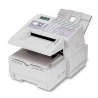
Service Guide OKIFAX 5750/5950 Page: 7 Chapter 1 General Information 1.4.1 General Appearance of OKIFAX 5750/5950 Figure 1.4.1 shows the general appearance of the OKIFAX 5750/5950. Figure 1.4.1 General Appearance of OKIFAX 5750/5950. - Page 28 Copyright 2000, Oki Data, Division of OKI America, Inc. All rights reserved. See the Oki Data Business Partner Exchange (BPX) for any updates to this material. (http://bpx.okidata.com)
-
Page 29: Control Panel
Service Guide OKIFAX 5750/5950 Page: 9 Chapter 1 General Information 1.4.2 Control Panel Copyright 2000, Oki Data, Division of OKI America, Inc. All rights reserved. See the Oki Data Business Partner Exchange (BPX) for any updates to this material. (http://bpx.okidata.com) -
Page 30: Basic Performance Specifications
Table 1.5.1 (6/8) Basic Performance Specifications Table 1.5.1 (7/8) Basic Performance Specifications Table 1.5.1 (8/8) Basic Performance Specifications Copyright 2000, Oki Data, Division of OKI America, Inc. All rights reserved. See the Oki Data Business Partner Exchange (BPX) for any updates to this material. (http://bpx.okidata.com) -
Page 31: Table 1.5.1 (1/8) Basic Performance Specifications
Service Guide OKIFAX 5750/5950 Page: 11 Chapter 1 General Information Table 1.5.1 (1/8) Basic Performance Specifications Item Specifications Applicable line 1) PSTN (Public switched telephone network) 2) PBX (Private branch exchange) 3) ISDN (Integrated services digital network): Option 4) LAN (Local area network): Option... - Page 32 Copyright 2000, Oki Data, Division of OKI America, Inc. All rights reserved. See the Oki Data Business Partner Exchange (BPX) for any updates to this material. (http://bpx.okidata.com)
-
Page 33: Table 1.5.1 (2/8) Basic Performance Specifications
Service Guide OKIFAX 5750/5950 Page: 12 Chapter 1 General Information Table 1.5.1 (2/8) Basic Performance Specifications Item Specifications Effective reading width Document width Communication Effective reading width Copy size Mode/Paper width ISO A4 (210 mm) G3/A4 208.6 mm for TX [INTL] 208.6 mm for local copy... - Page 34 Document jam removal Manual release Copyright 2000, Oki Data, Division of OKI America, Inc. All rights reserved. See the Oki Data Business Partner Exchange (BPX) for any updates to this material. (http://bpx.okidata.com)
-
Page 35: Table 1.5.1 (3/8) Basic Performance Specifications
3) Weight, thickness and condition: Same as above Note: One single sheet should be loaded on the manual paper feeder for one occasion. For best results use Oki Data recommended papers 1) Xerox 4200 (20 - lb/75 gm base weight paper) - Page 36 (Oki Data recommended paper) second cassette Up to 500 sheets/cassette (Oki Data recommended paper) Copyright 2000, Oki Data, Division of OKI America, Inc. All rights reserved. See the Oki Data Business Partner Exchange (BPX) for any updates to this material. (http://bpx.okidata.com)
-
Page 37: Table 1.5.1 (4/8) Basic Performance Specifications
Service Guide OKIFAX 5750/5950 Page: 14 Chapter 1 General Information Table 1.5.1 (4/8) Basic Performance Specifications Item Specifications Effective recording area 1) Printable area Letter Size A4 Size 14 inch Legal Size 13 inch Legal Size inch inch inch inch 279.4... - Page 38 These tables do not include vertical and horizontal addressing error (+/- 3 mm) of recording paper. Copyright 2000, Oki Data, Division of OKI America, Inc. All rights reserved. See the Oki Data Business Partner Exchange (BPX) for any updates to this material. (http://bpx.okidata.com)
-
Page 39: Table 1.5.1 (5/8) Basic Performance Specifications
Service Guide OKIFAX 5750/5950 Page: 15 Chapter 1 General Information Table 1.5.1 (5/8) Basic Performance Specifications Item Specifications Copy stacking The printed copies will be discharged on the stacker with printed face up or face down. 1) Face down stacking: Up to 200 copies... - Page 40 LCD display will show "MSG. IN MEMORY", and the ALARM LED turns on. Copyright 2000, Oki Data, Division of OKI America, Inc. All rights reserved. See the Oki Data Business Partner Exchange (BPX) for any updates to this material. (http://bpx.okidata.com)
-
Page 42: Table 1.5.1 (6/8) Basic Performance Specifications
Table 1.5.1 (6/8) Basic Performance Specifications Item Specifications Minimum scan line time for 0 ms, when receiving in ECM mode or from an Oki Data receiving facsimile. 5 ms at 15.4 line/mm or 7.7 line/mm and 10 ms at 3.85 line/mm when receiving from a non-Oki Data facsimile or non-ECM mode. - Page 43 Note: In High-speed protocol, V.34 is not applied. 3) ITU-T G4 Class 1 (option) Copyright 2000, Oki Data, Division of OKI America, Inc. All rights reserved. See the Oki Data Business Partner Exchange (BPX) for any updates to this material. (http://bpx.okidata.com)
-
Page 44: Table 1.5.1 (7/8) Basic Performance Specifications
Specifications Transmission time 2.5 seconds at 33.6 kbps with JBIG for OKIFAX 5950 and 3.0 seconds at 33.6 kbps for OKIFAX 5750 per sheet of ITU-T No. 1 evaluation test chart. Note: This speed denotes the time interval corresponding to Phase C (message transmission phase) as referred to in ITU-T T.30. - Page 45 Copyright 2000, Oki Data, Division of OKI America, Inc. All rights reserved. See the Oki Data Business Partner Exchange (BPX) for any updates to this material. (http://bpx.okidata.com)
-
Page 46: Table 1.5.1 (8/8) Basic Performance Specifications
Note 2: For details, see Product Spec. "MFP-PC Interface Kit." Network print service This function can be used for OKIFAX 5750/5950 network printer (option) service. The OkiHSP NIC (Network Interface Card) Ethernet Adapter used for OKIFAX 5750/5950 is originally designed for the OkiPage printers and is intended to be forward compatible with (future) products utilizing an OkiHSP compatible interface. - Page 47 Note, for details see Product Spec "600 dpi Communication". Relay Broadcast Function G4 communication supports Oki mode relay broad-cast only. G3 communication supports both Oki mode relay broadcast and F code relay broadcast. Note: For details, see Product Spec. "Relay Broadcast Function".
- Page 48 Virtual E-mail Web Retrieval Note: For details, see Product Spec. "FAX2NET Specifications". Power supply unit and Power consumption of the machine Power consumption of the machine Mode Typical power (W) Transmit 25 W Receive 325 W Local copy 330 W Standby 9.0 W Note:...
- Page 49 6) One touch sheet x 1 (Already installed) 7) User's guide x 1 Copyright 2000, Oki Data, Division of OKI America, Inc. All rights reserved. See the Oki Data Business Partner Exchange (BPX) for any updates to this material. (http://bpx.okidata.com)
-
Page 50: Reports And Lists
Service Guide OKIFAX 5750/5950 Page: 19 Chapter 1 General Information 1.6 Reports and Lists Table 1.6.1 Configuration Report (List of Setting) Table 1.6.2 Difference from OKIFAX 5700/5900 1.6.3 Help Report 1.6.4 Telephone Directory 1.6.5 Group Directory 1.6.6 Self-Diagnosis Report 1.6.7 G3 Protocol Dump 1.6.8 G4 Protocol Dump... - Page 51 Copyright 2000, Oki Data, Division of OKI America, Inc. All rights reserved. See the Oki Data Business Partner Exchange (BPX) for any updates to this material. (http://bpx.okidata.com)
-
Page 52: Configuration Report (List Of Setting)
Service Guide OKIFAX 5750/5950 Page: 21 Chapter 1 General Information 1.6.1 Configuration Report (List of Setting) Purpose: To allow the user or serviceman to obtain a list of features and functions available with the machine, so that operator can rearrange the machine configuration for a most efficient operating environment with the machine. - Page 53 16. Technical Programmed Function Parameters: Technical Function Setup (No. 01 to No. 45) Copyright 2000, Oki Data, Division of OKI America, Inc. All rights reserved. See the Oki Data Business Partner Exchange (BPX) for any updates to this material. (http://bpx.okidata.com)
-
Page 54: Difference From Okifax
*13 Described when 8MB option memory is installed. *14 To be described whether Fax2Net server is enabled. Copyright 2000, Oki Data, Division of OKI America, Inc. All rights reserved. See the Oki Data Business Partner Exchange (BPX) for any updates to this material. (http://bpx.okidata.com) -
Page 55: Report Image
Service Guide OKIFAX 5750/5950 Page: 21 Chapter 1 General Information 1.6.1.2 Report Image... - Page 60 Copyright 2000, Oki Data, Division of OKI America, Inc. All rights reserved. See the Oki Data Business Partner Exchange (BPX) for any updates to this material. (http://bpx.okidata.com)
-
Page 61: Function List
The list is printed out user function only and does not print technical function. Copyright 2000, Oki Data, Division of OKI America, Inc. All rights reserved. See the Oki Data Business Partner Exchange (BPX) for any updates to this material. (http://bpx.okidata.com) -
Page 62: Difference From Okifax
* Moved CLOCK ADJUSTMENT, and ID/PASSWORD PRG. to page 2, and INCOMING OPTIONS to page 3 due to the addition of descriptions. Copyright 2000, Oki Data, Division of OKI America, Inc. All rights reserved. See the Oki Data Business Partner Exchange... -
Page 63: Report Image
Service Guide OKIFAX 5750/5950 Page: 21 Chapter 1 General Information 1.6.2.2 Report Image... - Page 67 Copyright 2000, Oki Data, Division of OKI America, Inc. All rights reserved. See the Oki Data Business Partner Exchange (BPX) for any updates to this material. (http://bpx.okidata.com)
-
Page 68: Help Report
Output the following new report by pressing HELP key while the device is in standby state. Following this report, output conventional function list. (4 sheets in total) Copyright 2000, Oki Data, Division of OKI America, Inc. All rights reserved. See the Oki Data Business Partner Exchange (BPX) for any updates to this material. (http://bpx.okidata.com) -
Page 69: Report Image (Conditions For Description)
Service Guide OKIFAX 5750/5950 Page: 21 Chapter 1 General Information 1.6.3.1 Report Image (Conditions for Description) (1) If the line for descriptions is in blank, don’t move up descriptions in the following lines. (Keep the blank line blank.) - Page 71 Copyright 2000, Oki Data, Division of OKI America, Inc. All rights reserved. See the Oki Data Business Partner Exchange (BPX) for any updates to this material. (http://bpx.okidata.com)
-
Page 72: Telephone Directory
The report will be manually printed out. The report prints destinations registered only. Descriptions: Five pages for OKIFAX 5750 and eight pages for OKIFAX 5950. Speed Dial: Up to 140 for OKIFAX 5750, up to 230 for OKIFAX 5950 1. Title of the report 2. -
Page 73: Difference From Okifax
* Character string including lower-case alphabetic characters and symbols. * Max. 64 characters Copyright 2000, Oki Data, Division of OKI America, Inc. All rights reserved. See the Oki Data Business Partner Exchange (BPX) for any updates to this material. (http://bpx.okidata.com) -
Page 74: Telephone Directory P1 For Of5750
Service Guide OKIFAX 5750/5950 Page: 21 Chapter 1 General Information Telephone Directory P1 for OF5750... - Page 76 Copyright 2000, Oki Data, Division of OKI America, Inc. All rights reserved. See the Oki Data Business Partner Exchange (BPX) for any updates to this material. (http://bpx.okidata.com)
-
Page 77: Telephone Directory P2 For Of5750
Service Guide OKIFAX 5750/5950 Page: 21 Chapter 1 General Information Telephone Directory P2 for OF5750... - Page 79 Copyright 2000, Oki Data, Division of OKI America, Inc. All rights reserved. See the Oki Data Business Partner Exchange (BPX) for any updates to this material. (http://bpx.okidata.com)
-
Page 80: Telephone Directory P3 For Of5750
Service Guide OKIFAX 5750/5950 Page: 21 Chapter 1 General Information Telephone Directory P3 for OF5750... - Page 82 Copyright 2000, Oki Data, Division of OKI America, Inc. All rights reserved. See the Oki Data Business Partner Exchange (BPX) for any updates to this material. (http://bpx.okidata.com)
-
Page 83: Telephone Directory P4 For Of5750
Service Guide OKIFAX 5750/5950 Page: 21 Chapter 1 General Information Telephone Directory P4 for OF5750... - Page 85 Copyright 2000, Oki Data, Division of OKI America, Inc. All rights reserved. See the Oki Data Business Partner Exchange (BPX) for any updates to this material. (http://bpx.okidata.com)
-
Page 86: Telephone Directory P5 For Of5750
Service Guide OKIFAX 5750/5950 Page: 21 Chapter 1 General Information Telephone Directory P5 for OF5750... - Page 87 Copyright 2000, Oki Data, Division of OKI America, Inc. All rights reserved. See the Oki Data Business Partner Exchange (BPX) for any updates to this material. (http://bpx.okidata.com)
-
Page 88: Telephone Directory P1 For Of5950
Service Guide OKIFAX 5750/5950 Page: 21 Chapter 1 General Information Telephone Directory P1 for OF5950... - Page 90 Copyright 2000, Oki Data, Division of OKI America, Inc. All rights reserved. See the Oki Data Business Partner Exchange (BPX) for any updates to this material. (http://bpx.okidata.com)
-
Page 91: Telephone Directory P2 For Of5950
Service Guide OKIFAX 5750/5950 Page: 21 Chapter 1 General Information Telephone Directory P2 for OF5950... - Page 93 Copyright 2000, Oki Data, Division of OKI America, Inc. All rights reserved. See the Oki Data Business Partner Exchange (BPX) for any updates to this material. (http://bpx.okidata.com)
-
Page 94: Telephone Directory P3 For Of5950
Service Guide OKIFAX 5750/5950 Page: 21 Chapter 1 General Information Telephone Directory P3 for OF5950... - Page 96 Copyright 2000, Oki Data, Division of OKI America, Inc. All rights reserved. See the Oki Data Business Partner Exchange (BPX) for any updates to this material. (http://bpx.okidata.com)
-
Page 97: Telephone Directory P4 For Of5950
Service Guide OKIFAX 5750/5950 Page: 21 Chapter 1 General Information Telephone Directory P4 for OF5950... - Page 99 Copyright 2000, Oki Data, Division of OKI America, Inc. All rights reserved. See the Oki Data Business Partner Exchange (BPX) for any updates to this material. (http://bpx.okidata.com)
-
Page 100: Telephone Directory P5 For Of5950
Service Guide OKIFAX 5750/5950 Page: 21 Chapter 1 General Information Telephone Directory P5 for OF5950... - Page 102 Copyright 2000, Oki Data, Division of OKI America, Inc. All rights reserved. See the Oki Data Business Partner Exchange (BPX) for any updates to this material. (http://bpx.okidata.com)
-
Page 103: Telephone Directory P6 For Of5950
Service Guide OKIFAX 5750/5950 Page: 21 Chapter 1 General Information Telephone Directory P6 for OF5950 Copyright 2000, Oki Data, Division of OKI America, Inc. All rights reserved. See the Oki Data Business Partner Exchange (BPX) for any updates to this material. (http://bpx.okidata.com) - Page 104 Service Guide OKIFAX 5750/5950 Page: 21 Chapter 1 General Information Telephone Directory P6 for OF5950...
- Page 106 Copyright 2000, Oki Data, Division of OKI America, Inc. All rights reserved. See the Oki Data Business Partner Exchange (BPX) for any updates to this material. (http://bpx.okidata.com)
-
Page 107: Telephone Directory P7 For Of5950
Service Guide OKIFAX 5750/5950 Page: 21 Chapter 1 General Information Telephone Directory P7 for OF5950... - Page 109 Copyright 2000, Oki Data, Division of OKI America, Inc. All rights reserved. See the Oki Data Business Partner Exchange (BPX) for any updates to this material. (http://bpx.okidata.com)
-
Page 110: Telephone Directory P8 For Of5950
Service Guide OKIFAX 5750/5950 Page: 21 Chapter 1 General Information Telephone Directory P8 for OF5950... - Page 111 Copyright 2000, Oki Data, Division of OKI America, Inc. All rights reserved. See the Oki Data Business Partner Exchange (BPX) for any updates to this material. (http://bpx.okidata.com)
-
Page 112: Telephone Directory
Telephone Directory (When the destination is registered by SPEED DIAL No. 1, No. 50 and No. 100 only). Copyright 2000, Oki Data, Division of OKI America, Inc. All rights reserved. See the Oki Data Business Partner Exchange (BPX) for any updates to this material. (http://bpx.okidata.com) -
Page 113: Group Directory
4. Registered Group No. and ID 5. Registered location ID (up to 40 characters) Copyright 2000, Oki Data, Division of OKI America, Inc. All rights reserved. See the Oki Data Business Partner Exchange (BPX) for any updates to this material. (http://bpx.okidata.com) -
Page 114: Difference From Okifax5700/5900
* Max. 40 characters. If the number of characters exceeds 40, description will be made from the top. Copyright 2000, Oki Data, Division of OKI America, Inc. All rights reserved. See the Oki Data Business Partner Exchange (BPX) for any updates to this material. (http://bpx.okidata.com) -
Page 115: Group Directory For Okifax5750
Service Guide OKIFAX 5750/5950 Page: 21 Chapter 1 General Information Group Directory for OKIFAX5750... - Page 117 Copyright 2000, Oki Data, Division of OKI America, Inc. All rights reserved. See the Oki Data Business Partner Exchange (BPX) for any updates to this material. (http://bpx.okidata.com)
-
Page 118: Group Directory P1 For Okifax5950
Service Guide OKIFAX 5750/5950 Page: 21 Chapter 1 General Information Group Directory P1 for OKIFAX5950... - Page 120 Copyright 2000, Oki Data, Division of OKI America, Inc. All rights reserved. See the Oki Data Business Partner Exchange (BPX) for any updates to this material. (http://bpx.okidata.com)
-
Page 121: Group Directory P2 For Okifax5950
Service Guide OKIFAX 5750/5950 Page: 21 Chapter 1 General Information Group Directory P2 for OKIFAX5950... - Page 122 Copyright 2000, Oki Data, Division of OKI America, Inc. All rights reserved. See the Oki Data Business Partner Exchange...
- Page 123 (BPX) for any updates to this material. (http://bpx.okidata.com)
-
Page 124: Group Directory
OF5750/5950 Series January 2001 Group Directory (When the destination of SPEED DIAL No. 1, No. 50, and No. 100 is selected by the group designation.) Copyright 2000, Oki Data, Division of OKI America, Inc. All rights reserved. See the Oki Data Business Partner Exchange... -
Page 125: Self Diagnosis Report
To check ROMs, RAMs and Printing function Method: The report will be manually printed out for maintenance purpose. Copyright 2000, Oki Data, Division of OKI America, Inc. All rights reserved. See the Oki Data Business Partner Exchange (BPX) for any updates to this material. (http://bpx.okidata.com) -
Page 126: Difference From Okifax5700/Of5900
(Status window failed to show normal value.) *4 Describe the TONER/ID lockout identification information 4 digits (0 or 1). Copyright 2000, Oki Data, Division of OKI America, Inc. All rights reserved. See the Oki Data Business Partner Exchange (BPX) for any updates to this material. (http://bpx.okidata.com) -
Page 127: Report Image
Service Guide OKIFAX 5750/5950 Page: 21 Chapter 1 General Information 1.6.6.2 Report Image... - Page 129 Copyright 2000, Oki Data, Division of OKI America, Inc. All rights reserved. See the Oki Data Business Partner Exchange (BPX) for any updates to this material. (http://bpx.okidata.com)
-
Page 130: G3 Protocol Dump
Service Guide OKIFAX 5750/5950 Page: 21 Chapter 1 General Information 1.6.7 G3 Protocol Dump Purpose: To allow the serviceman to obtain a list of protocol signals transferred between the transmitter and receiver. Method: The report will be manually printed out for maintenance purpose. If the previous communication is G3, G3 communication protocol dump is printed out. If it is G4, the G4 communication protocol dump is printed. - Page 131 21. Received SID 22. Common information of ITU-T V.34 TX/RX (page2) 23. Modem trace (page2) Copyright 2000, Oki Data, Division of OKI America, Inc. All rights reserved. See the Oki Data Business Partner Exchange (BPX) for any updates to this material. (http://bpx.okidata.com)
-
Page 132: Difference From Okifax5700/Of5900
Describe "#" symbol to the descriptions of information on the result of communication for communication using G3 option. (see 1.6.11 "Activity Report") Copyright 2000, Oki Data, Division of OKI America, Inc. All rights reserved. See the Oki Data Business Partner Exchange... -
Page 133: Protocol Dump P1
Service Guide OKIFAX 5750/5950 Page: 21 Chapter 1 General Information Protocol Dump P1... - Page 135 Copyright 2000, Oki Data, Division of OKI America, Inc. All rights reserved. See the Oki Data Business Partner Exchange (BPX) for any updates to this material. (http://bpx.okidata.com)
-
Page 136: Protocol Dump P2
Service Guide OKIFAX 5750/5950 Page: 21 Chapter 1 General Information Protocol Dump P2 Copyright 2000, Oki Data, Division of OKI America, Inc. All rights reserved. See the Oki Data Business Partner Exchange (BPX) for any updates to this material. (http://bpx.okidata.com) -
Page 138: G4 Protocol Dump
Service Guide OKIFAX 5750/5950 Page: 21 Chapter 1 General Information 1.6.8 G4 Protocol Dump Purpose: To allow the serviceman to obtain a list of protocol signals transferred between the transmitter and receiver. Method: The report will be manually printed out for maintenance purpose. - Page 139 21. TBR/TCC/TCR/TCA 22. CSS 23. RSSP/RSSN 24. CD/CL 25. RDCLP 26. CDS 27. CDUI Copyright 2000, Oki Data, Division of OKI America, Inc. All rights reserved. See the Oki Data Business Partner Exchange (BPX) for any updates to this material. (http://bpx.okidata.com)
- Page 140 Service Guide OKIFAX 5750/5950 Page: 21 Chapter 1 General Information Protocol Dump P1...
- Page 142 Copyright 2000, Oki Data, Division of OKI America, Inc. All rights reserved. See the Oki Data Business Partner Exchange (BPX) for any updates to this material. (http://bpx.okidata.com)
- Page 143 Service Guide OKIFAX 5750/5950 Page: 21 Chapter 1 General Information Protocol Dump P2...
- Page 145 Copyright 2000, Oki Data, Division of OKI America, Inc. All rights reserved. See the Oki Data Business Partner Exchange (BPX) for any updates to this material. (http://bpx.okidata.com)
-
Page 146: Relay Broadcast Confirmation
Report" for automatic output as stated below: "BROADCAST CONFIRMATION REPORT" to "RELAY BROADCAST CONFIRMATION" Copyright 2000, Oki Data, Division of OKI America, Inc. All rights reserved. See the Oki Data Business Partner Exchange (BPX) for any updates to this material. (http://bpx.okidata.com) - Page 147 Service Guide OKIFAX 5750/5950 Page: 21 Chapter 1 General Information Relay Broadcast Confirmation Report P1 for OKIFAX 5750...
- Page 149 Copyright 2000, Oki Data, Division of OKI America, Inc. All rights reserved. See the Oki Data Business Partner Exchange (BPX) for any updates to this material. (http://bpx.okidata.com)
- Page 150 Page: 21 Chapter 1 General Information Relay Broadcast Confirmation Report P2 for OKIFAX 5750 Copyright 2000, Oki Data, Division of OKI America, Inc. All rights reserved. See the Oki Data Business Partner Exchange (BPX) for any updates to this material. (http://bpx.okidata.com)
- Page 151 Service Guide OKIFAX 5750/5950 Page: 21 Chapter 1 General Information Relay Broadcast Confirmation Report P1 for OKIFAX 5950...
- Page 153 Copyright 2000, Oki Data, Division of OKI America, Inc. All rights reserved. See the Oki Data Business Partner Exchange (BPX) for any updates to this material. (http://bpx.okidata.com)
- Page 154 Service Guide OKIFAX 5750/5950 Page: 21 Chapter 1 General Information Relay Broadcast Confirmation Report P2 for OKIFAX 5950...
- Page 156 Copyright 2000, Oki Data, Division of OKI America, Inc. All rights reserved. See the Oki Data Business Partner Exchange (BPX) for any updates to this material. (http://bpx.okidata.com)
-
Page 157: Internet Fax Reception Error Report (Error Mail
Descriptions of the content of communication are same as for the Reception of Internet FAX of (1), (3)-(5) of "1.6.11 Activity Report". Copyright 2000, Oki Data, Division of OKI America, Inc. All rights reserved. See the Oki Data Business Partner Exchange... -
Page 158: Report Relay Broadcast Confirmation Report
Relay Broadcast Confirmation Report (When the destination is specified by SPEED DIAL No. 1, No. 50, No. 100, and KEYPAD). Copyright 2000, Oki Data, Division of OKI America, Inc. All rights reserved. See the Oki Data Business Partner Exchange (BPX) for any updates to this material. (http://bpx.okidata.com) -
Page 159: Activity Report
11. Result of the communication OK/NO/STOP/BUSY/PAPER/COMP (Complection of broadcast)/S JAM/R JAM/COVER/CANCEL 12. Service code Copyright 2000, Oki Data, Division of OKI America, Inc. All rights reserved. See the Oki Data Business Partner Exchange (BPX) for any updates to this material. (http://bpx.okidata.com) - Page 161 Service Guide OKIFAX 5750/5950 Page: 21 Chapter 1 General Information 1.6.11.1 Difference from OKIFAX5700/5900 (1) Describes Internet FAX, Fax2Net Email/WEB address to DISTANT STATION ID. Character string including the lower-case alphabetic characters and symbols Leading 24 characters Describes Speed Dial registered address ID when transmitting Internet Fax, and Fax2Net (Email transmission, Web Retrieval).
- Page 162 Copyright 2000, Oki Data, Division of OKI America, Inc. All rights reserved. See the Oki Data Business Partner Exchange (BPX) for any updates to this material. (http://bpx.okidata.com)
- Page 163 Service Guide OKIFAX 5750/5950 Page: 21 Chapter 1 General Information Activity Report...
- Page 164 Copyright 2000, Oki Data, Division of OKI America, Inc. All rights reserved. See the Oki Data Business Partner Exchange (BPX) for any updates to this material. (http://bpx.okidata.com)
-
Page 165: Message Confirmation
4. Total TX and total RX time 5. Date of transmission or reception 6. Time when the communication started 7. Length of time for which the OKIFAX 5750/5950 was connected to the line 8. Identification of the remote station Personal ID/CSI(TSI)/Location ID/Dial number/Called TID/Calling TID 9. - Page 166 1.6.12.1 Difference from OKIFAX5700/5900 Same as (1)-(5) of “1.6.11 Activity Report.” Copyright 2000, Oki Data, Division of OKI America, Inc. All rights reserved. See the Oki Data Business Partner Exchange (BPX) for any updates to this material. (http://bpx.okidata.com)
- Page 167 Chapter 1 General Information 1.6.12.1 Difference from OKIFAX5700/5900 Same as (1)-(5) of "1.6.11 Activity Report." Copyright 2000, Oki Data, Division of OKI America, Inc. All rights reserved. See the Oki Data Business Partner Exchange (BPX) for any updates to this material. (http://bpx.okidata.com)
-
Page 168: Message Confirmation (When The Transmission Is The
Service Guide OKIFAX 5750/5950 Page: 21 Chapter 1 General Information Message Confirmation (When the transmission is the normal end) - Page 170 Copyright 2000, Oki Data, Division of OKI America, Inc. All rights reserved. See the Oki Data Business Partner Exchange (BPX) for any updates to this material. (http://bpx.okidata.com)
- Page 171 Service Guide OKIFAX 5750/5950 Page: 21 Chapter 1 General Information Message Confirmation (Error Report)
- Page 173 Copyright 2000, Oki Data, Division of OKI America, Inc. All rights reserved. See the Oki Data Business Partner Exchange (BPX) for any updates to this material. (http://bpx.okidata.com)
-
Page 174: Power Outage Report
9. Total number of reserved documents or transmitted pages 10. Result of the communication LOST Copyright 2000, Oki Data, Division of OKI America, Inc. All rights reserved. See the Oki Data Business Partner Exchange (BPX) for any updates to this material. (http://bpx.okidata.com) - Page 175 However, description of MODE column for Fax2Net (G3) transmission will be "CALLING" instead of "FNET." Copyright 2000, Oki Data, Division of OKI America, Inc. All rights reserved. See the Oki Data Business Partner Exchange (BPX) for any updates to this material. (http://bpx.okidata.com)
- Page 176 Service Guide OKIFAX 5750/5950 Page: 21 Chapter 1 General Information Power Outage Report Copyright 2000, Oki Data, Division of OKI America, Inc. All rights reserved. See the Oki Data Business Partner Exchange (BPX) for any updates to this material. (http://bpx.okidata.com)
-
Page 177: Confidential Rx Report
11. Service code 1.6.14.1 Difference from OKIFAX5700/5900 Same as (2) of “1.6.11. Activity Report.” Copyright 2000, Oki Data, Division of OKI America, Inc. All rights reserved. See the Oki Data Business Partner Exchange (BPX) for any updates to this material. (http://bpx.okidata.com) - Page 178 Chapter 1 General Information 1.6.14.1 Difference from OKIFAX5700/5900 Same as (2) of "1.6.11. Activity Report." Copyright 2000, Oki Data, Division of OKI America, Inc. All rights reserved. See the Oki Data Business Partner Exchange (BPX) for any updates to this material. (http://bpx.okidata.com)
- Page 179 Service Guide OKIFAX 5750/5950 Page: 21 Chapter 1 General Information Confidential RX Report Copyright 2000, Oki Data, Division of OKI America, Inc. All rights reserved. See the Oki Data Business Partner Exchange (BPX) for any updates to this material. (http://bpx.okidata.com)
-
Page 180: Active Memory File
Service Guide OKIFAX 5750/5950 Page: 21 Chapter 1 General Information 1.6.15 Active Memory File Method: The report will be manually or automatically printed out for information of transmission/reception data stored in the memory. When there is no stored image data in the memory at all, the Active Memory Files is not printed out. - Page 181 Copyright 2000, Oki Data, Division of OKI America, Inc. All rights reserved. See the Oki Data Business Partner Exchange (BPX) for any updates to this material. (http://bpx.okidata.com)
- Page 182 Descriptions of Internet FAX and/or Fax2Net (Email or Web or G3) queuing for redial. Description for queuing for relay broadcast Copyright 2000, Oki Data, Division of OKI America, Inc. All rights reserved. See the Oki Data Business Partner Exchange (BPX) for any updates to this material. (http://bpx.okidata.com)
- Page 183 Service Guide OKIFAX 5750/5950 Page: 21 Chapter 1 General Information Active Memory Files P1...
- Page 185 Copyright 2000, Oki Data, Division of OKI America, Inc. All rights reserved. See the Oki Data Business Partner Exchange (BPX) for any updates to this material. (http://bpx.okidata.com)
- Page 186 Service Guide OKIFAX 5750/5950 Page: 21 Chapter 1 General Information Active Memory Files P2 Copyright 2000, Oki Data, Division of OKI America, Inc. All rights reserved. See the Oki Data Business Partner Exchange (BPX) for any updates to this material. (http://bpx.okidata.com)
-
Page 187: Active Memory Files (In Case Of Within 1 Page)
Chapter 1 General Information Active Memory Files (In case of within 1 page) Copyright 2000, Oki Data, Division of OKI America, Inc. All rights reserved. See the Oki Data Business Partner Exchange (BPX) for any updates to this material. (http://bpx.okidata.com) -
Page 188: Broadcast Entry Report
4. Required transmission address (Speed dial) 5. Registered location ID 6. Required transmission address (Ten key dial) Copyright 2000, Oki Data, Division of OKI America, Inc. All rights reserved. See the Oki Data Business Partner Exchange (BPX) for any updates to this material. (http://bpx.okidata.com) - Page 189 Speed Dial: Descriptions of maximum 40 characters. If exceeding 40 characters, description starts from the top. Keypad: All 64 characters enabled Copyright 2000, Oki Data, Division of OKI America, Inc. All rights reserved. See the Oki Data Business Partner Exchange (BPX) for any updates to this material. (http://bpx.okidata.com)
- Page 190 Service Guide OKIFAX 5750/5950 Page: 21 Chapter 1 General Information Broadcast Entry Report P1...
- Page 192 Copyright 2000, Oki Data, Division of OKI America, Inc. All rights reserved. See the Oki Data Business Partner Exchange (BPX) for any updates to this material. (http://bpx.okidata.com)
- Page 193 Service Guide OKIFAX 5750/5950 Page: 21 Chapter 1 General Information Broadcast Entry Report P2 Copyright 2000, Oki Data, Division of OKI America, Inc. All rights reserved. See the Oki Data Business Partner Exchange (BPX) for any updates to this material. (http://bpx.okidata.com)
-
Page 194: Broadcast Entry Report P1 For Okifax 5950 (1/2)
Service Guide OKIFAX 5750/5950 Page: 21 Chapter 1 General Information Broadcast Entry Report P1 for OKIFAX 5950 (1/2) - Page 196 Copyright 2000, Oki Data, Division of OKI America, Inc. All rights reserved. See the Oki Data Business Partner Exchange (BPX) for any updates to this material. (http://bpx.okidata.com)
-
Page 197: Broadcast Entry Report P1 For Okifax 5950 (2/2)
Service Guide OKIFAX 5750/5950 Page: 21 Chapter 1 General Information Broadcast Entry Report P1 for OKIFAX 5950 (2/2) - Page 199 Copyright 2000, Oki Data, Division of OKI America, Inc. All rights reserved. See the Oki Data Business Partner Exchange (BPX) for any updates to this material. (http://bpx.okidata.com)
-
Page 200: Broadcast Entry Report (When The Destination Of
Broadcast Entry Report (When the destination of Broadcast TX is specified by SPEED DIAL No. 1, No. 50, and No. 100) Copyright 2000, Oki Data, Division of OKI America, Inc. All rights reserved. See the Oki Data Business Partner Exchange... -
Page 201: Broadcast Confirmation Report
Since simultaneous transmission of Internet FAX effects transmission to respective addresses at one time, the result will be either all OK or failure (NG). Copyright 2000, Oki Data, Division of OKI America, Inc. All rights reserved. See the Oki Data Business Partner Exchange... -
Page 202: Relay Broadcast Entry Report
When the relay personal box is opened, the relay broadcast entry report can be output in the specified operation of the delivery address. (Format is the same as the conventional broadcast entry report but the following description only differs.) Copyright 2000, Oki Data, Division of OKI America, Inc. All rights reserved. See the Oki Data Business Partner Exchange (BPX) for any updates to this material. (http://bpx.okidata.com) -
Page 203: G3 Log Report
Report format is identical with MCNT and the log information by the firm of G4 option. Copyright 2000, Oki Data, Division of OKI America, Inc. All rights reserved. See the Oki Data Business Partner Exchange (BPX) for any updates to this material. (http://bpx.okidata.com) -
Page 204: Nic Configuration
Chapter 1 General Information 1.6.20 NIC Configuration Refer to the "Internet FAX System Specifications." Copyright 2000, Oki Data, Division of OKI America, Inc. All rights reserved. See the Oki Data Business Partner Exchange (BPX) for any updates to this material. (http://bpx.okidata.com) -
Page 205: Nic Configuration (Type 1 Oda Version)
Service Guide OKIFAX 5750/5950 Page: 21 Chapter 1 General Information NIC Configuration (Type 1 ODA Version) - Page 207 Copyright 2000, Oki Data, Division of OKI America, Inc. All rights reserved. See the Oki Data Business Partner Exchange (BPX) for any updates to this material. (http://bpx.okidata.com)
- Page 208 Service Guide OKIFAX 5750/5950 Page: 21 Chapter 1 General Information NIC Configuration (Type 2) Copyright 2000, Oki Data, Division of OKI America, Inc. All rights reserved. See the Oki Data Business Partner Exchange (BPX) for any updates to this material. (http://bpx.okidata.com)
-
Page 209: Nic Information
Service Guide OKIFAX 5750/5950 Page: 21 Chapter 1 General Information 1.6.21 NIC Information... - Page 211 Copyright 2000, Oki Data, Division of OKI America, Inc. All rights reserved. See the Oki Data Business Partner Exchange (BPX) for any updates to this material. (http://bpx.okidata.com)
-
Page 212: E-Mail Maintenance Report
Service Guide OKIFAX 5750/5950 Page: 21 Chapter 1 General Information 1.6.22 E-mail Maintenance Report When EMAIL MAINTENANCE=ON (Setting by service personnel), e-mail is transmitted at 00:00 a.m. every day the following image format. - Page 213 <Note: No actual combination of G3 opt. and NIC opt. exists in the above figure.> *1: Satisfies the described condition of self diagnosis report.
- Page 214 Attaches "CR-LF" to the end of line at the time of new line. Copyright 2000, Oki Data, Division of OKI America, Inc. All rights reserved. See the Oki Data Business Partner Exchange (BPX) for any updates to this material. (http://bpx.okidata.com)
-
Page 215: Descriptions Of Communication Mode Column
1.6.23.1 Mode Column in Activity Report 1.6.23.2 Mode Column in MCF-multi Report (with/without pictures) Copyright 2000, Oki Data, Division of OKI America, Inc. All rights reserved. See the Oki Data Business Partner Exchange (BPX) for any updates to this material. (http://bpx.okidata.com) - Page 216 *3 Simultaneous or relay broadcast of IFAX will be effected for all the addresses at one transmission. Therefore, descriptions to the Activity Report will be in a single line. Copyright 2000, Oki Data, Division of OKI America, Inc. All rights reserved. See the Oki Data Business Partner Exchange (BPX) for any updates to this material. (http://bpx.okidata.com)
- Page 218 Page: 21 Chapter 1 General Information 1.6.23.2 Mode Column in MCF-multi Report (with/without pictures) Copyright 2000, Oki Data, Division of OKI America, Inc. All rights reserved. See the Oki Data Business Partner Exchange (BPX) for any updates to this material. (http://bpx.okidata.com)
-
Page 219: Output Conditions Of Various Mcf Reports During
1.6.24.4 Reports to be output upon the communication error end 1.6.24.5 Reports to be output when the communication is completed normally. Copyright 2000, Oki Data, Division of OKI America, Inc. All rights reserved. See the Oki Data Business Partner Exchange (BPX) for any updates to this material. (http://bpx.okidata.com) -
Page 220: Difference From Okifax5700/5900
Activity Report. To this end, result of the broadcast transmission to the last address is described to the Activity Report. Copyright 2000, Oki Data, Division of OKI America, Inc. All rights reserved. See the Oki Data Business Partner Exchange (BPX) for any updates to this material. (http://bpx.okidata.com) -
Page 221: Reports To Be Output When Queuing For Communication Is Cancelled
Service Guide OKIFAX 5750/5950 Page: 21 Chapter 1 General Information 1.6.24.2 Reports to be output when queuing for communication is canceled... - Page 222 Copyright 2000, Oki Data, Division of OKI America, Inc. All rights reserved. See the Oki Data Business Partner Exchange (BPX) for any updates to this material. (http://bpx.okidata.com)
-
Page 223: Reports To Be Output Upon Canceling Communication By Pressing Stop Key
Chapter 1 General Information 1.6.24.3 Reports to be output upon canceling communication by pressing STOP Key Copyright 2000, Oki Data, Division of OKI America, Inc. All rights reserved. See the Oki Data Business Partner Exchange (BPX) for any updates to this material. (http://bpx.okidata.com) -
Page 224: Reports To Be Output Upon The Communication Error End
Chapter 1 General Information 1.6.24.4 Reports to be output upon the communication error end Copyright 2000, Oki Data, Division of OKI America, Inc. All rights reserved. See the Oki Data Business Partner Exchange (BPX) for any updates to this material. (http://bpx.okidata.com) -
Page 225: Reports To Be Output When The Communication Is Completed Normally
*1: By Image in MCF setting, even though this setting is set to ON, MCF (MULTI) for relay broadcast is without picture. Copyright 2000, Oki Data, Division of OKI America, Inc. All rights reserved. See the Oki Data Business Partner Exchange... -
Page 226: Installation 2.1 General Setup Information
Service Guide OKIFAX 5750/5950 Page: 76 Chapter 2 Installation 2.1 General Setup Information The following flowchart outlines the installation procedure. - Page 229 #2: Memory board, G4 option board, LAN option board, Second cassette unit etc.,. Copyright 2000, Oki Data, Division of OKI America, Inc. All rights reserved. See the Oki Data Business Partner Exchange (BPX) for any updates to this material. (http://bpx.okidata.com)
-
Page 230: Site Selection
Service Guide OKIFAX 5750/5950 Page: 77 Chapter 2 Installation 2.2 Site Selection INSTALLATION Precautions for Installation Fluctuation in line voltage 120V AC (102V to 127V) 230V AC (198V to 264V) Room temperature 50 to 90 degrees Fahrenheit (10 to 32 degrees Celsius) - Page 232 This space is necessary for installing the document stacker and allow space for the fan exhaust. Copyright 2000, Oki Data, Division of OKI America, Inc. All rights reserved. See the Oki Data Business Partner Exchange (BPX) for any updates to this material. (http://bpx.okidata.com)
-
Page 233: Unpacking
Service Guide OKIFAX 5750/5950 Page: 78 Chapter 2 Installation 2.3 Unpacking Procedure Remove tape on the top of the carton box and open its cover. Figure 2.3.1.1 Unpacking Procedure (1) Take out the accessory box from the carton box. (See Figure below 2.3) - Page 235 Copyright 2000, Oki Data, Division of OKI America, Inc. All rights reserved. See the Oki Data Business Partner Exchange (BPX) for any updates to this material. (http://bpx.okidata.com)
-
Page 236: Contents Idenfication
Document stacker Telephone line code Once touch sheet Already installed. User's Guide 1 volume Copyright 2000, Oki Data, Division of OKI America, Inc. All rights reserved. See the Oki Data Business Partner Exchange (BPX) for any updates to this material. (http://bpx.okidata.com) -
Page 237: Installation Of Attachments
Service Guide OKIFAX 5750/5950 Page: 80 Chapter 2 Installation 2.5 Installation of Attachments Items Image Drum (ID) Unit (already installed) Toner cartridge Recording paper Document stacker Procedure 1) Toner cartridge Peel off the fixed tape attached to the tray-paper. Open the cover-top. - Page 238 Figure 2.5.2 Toner Cartridge Installation (2) Take out the toner cartridge from the damp proof bag, shake it five or six times as shown in the illustration to eliminate the toner deflection, and peel off the seal gently. Figure 2.5.3 Toner Cartridge Installation (3) Ensure that the plastic tab on the right-hand side of the toner cartridge recess lines up with the groove on the toner cartridge.
- Page 239 Figure 2.5.4 Toner Cartridge Installation (4) Push the gray lever forward until it stops. Clean the toner scattered in the vicinity of the toner cartridge using a cloth moistened with cold water. Do not use hot water since it makes the toner stick there. Close the cover assembly-top until the buttons have been locked completely.
- Page 240 Remove the paper cassette from the facsimile by pulling the cassette tab. Sheets must not exceed the paper full marker of the new paper limit indication. If excessive sheets are set, it will cause paper jams. After loading the new paper, push it forward into the slot at the front of the facsimile until it locks. Document stacker Hang the document stacker onto hanging position.
- Page 241 Copyright 2000, Oki Data, Division of OKI America, Inc. All rights reserved. See the Oki Data Business Partner Exchange (BPX) for any updates to this material. (http://bpx.okidata.com)
-
Page 242: Ac Cord Connection
Turn the power switch ON and check that the display shows "(TIME and MEMORY FREE 100%)" message indicating the standby mode. Copyright 2000, Oki Data, Division of OKI America, Inc. All rights reserved. See the Oki Data Business Partner Exchange... -
Page 243: Telephone And Line Connections
Page: 82 Chapter 2 Installation 2.7 Telephone and Line Connections Procedure Connect the lines. Copyright 2000, Oki Data, Division of OKI America, Inc. All rights reserved. See the Oki Data Business Partner Exchange (BPX) for any updates to this material. (http://bpx.okidata.com) -
Page 244: Packing For Shipment
When packing the OKIFAX 5750/5950 for shipment, Failure to do this will result in damage to the machine. Copyright 2000, Oki Data, Division of OKI America, Inc. All rights reserved. See the Oki Data Business Partner Exchange (BPX) for any updates to this material. (http://bpx.okidata.com) -
Page 245: Initial Settings
2.9.7 Technical Default Setting 2.9.8 Default Setting of Dial Parameters 2.9.9 Off-line Tests 2.9.10 On-line Tests Copyright 2000, Oki Data, Division of OKI America, Inc. All rights reserved. See the Oki Data Business Partner Exchange (BPX) for any updates to this material. (http://bpx.okidata.com) -
Page 246: General Procedure Of Key Operation
Some of them cannot be used (skipped) depending on the destination of delivery and whether the machine is equipped with any option. Access numbers become discontinuous. Copyright 2000, Oki Data, Division of OKI America, Inc. All rights reserved. See the Oki Data Business Partner Exchange (BPX) for any updates to this material. (http://bpx.okidata.com) -
Page 247: User Functions
Service Guide OKIFAX 5750/5950 Page: 86 Chapter 2 Installation User Functions User Functions... -
Page 251: Technical Functions
Technical Functions... - Page 254 4) Typing a speed access number in the "TECHNICAL PRG. XX" (XX: 01 to 45) display allows you to bring up the setting or registration screen directly. Copyright 2000, Oki Data, Division of OKI America, Inc. All rights reserved. See the Oki Data Business Partner Exchange...
-
Page 255: Technical Functions Operation 1
Service Guide OKIFAX 5750/5950 Page: 88 Chapter 2 Installation 2.9.2.1 Technical Functions Operation 1 Select Menu is shown as below: 1. Local Test 2. Technical Setup: Go to Section 2.9.2.2 3. System Reset 4. Default Type Set 5. PC Loading 6. - Page 257 Copyright 2000, Oki Data, Division of OKI America, Inc. All rights reserved. See the Oki Data Business Partner Exchange (BPX) for any updates to this material. (http://bpx.okidata.com)
-
Page 258: Technical Functions Operation 2
Service Guide OKIFAX 5750/5950 Page: 89 Chapter 2 Installation 2.9.2.2 Technical Functions Operation 2... -
Page 269: T1 (Tx) Timer Value
2.9.2.2.1 T1 (TX) Timer Value Set the T1 timer (call connection wait time: XTTO) for transmission. Copyright 2000, Oki Data, Division of OKI America, Inc. All rights reserved. See the Oki Data Business Partner Exchange (BPX) for any updates to this material. (http://bpx.okidata.com) -
Page 270: T1 (Rx) Timer Value
Service Guide OKIFAX 5750/5950 Page: 91 Chapter 2 Installation 2.9.2.2.2 T1 (RX) Timer Value Set the T1 timer for reception. The time from issue of the first DIS to issue of a signal is checked. If a time-out occurs, the line is disconnected. - Page 271 Copyright 2000, Oki Data, Division of OKI America, Inc. All rights reserved. See the Oki Data Business Partner Exchange (BPX) for any updates to this material. (http://bpx.okidata.com)
-
Page 272: T2 Timer *100Ms
Registers the time duration (in seconds) for which the fax detects the EOL interval during reception of phase C. The fax disconnects the line when EOL cannot detect within T2 Timer. Copyright 2000, Oki Data, Division of OKI America, Inc. All rights reserved. See the Oki Data Business Partner Exchange (BPX) for any updates to this material. (http://bpx.okidata.com) -
Page 273: Error Criterion
Registers the threshold value whether to transmit RTN or MCF signal when the error occurs in received data. Copyright 2000, Oki Data, Division of OKI America, Inc. All rights reserved. See the Oki Data Business Partner Exchange (BPX) for any updates to this material. (http://bpx.okidata.com) -
Page 274: Attenuator
Adjusts the attenuation (dB) for the message send signal power level. Adjusting value is 0 to 15dB in one dB steps. Copyright 2000, Oki Data, Division of OKI America, Inc. All rights reserved. See the Oki Data Business Partner Exchange... -
Page 275: T/F Tone Att
Adjusts the attenuation (dB) for the send MF tone power level. Adjusting the value is 0 to 15dB in one dB steps. Copyright 2000, Oki Data, Division of OKI America, Inc. All rights reserved. See the Oki Data Business Partner Exchange... -
Page 276: Mf Att
Adjusts the attenuation (dB) for the send MF tone power level. Adjusting the value is 0 to 15dB in one dB steps. Copyright 2000, Oki Data, Division of OKI America, Inc. All rights reserved. See the Oki Data Business Partner Exchange... -
Page 277: Ring Dura. *10Ms
Selects the minimum ring detection time to meet country's requirements. Adjusting time is 100MS to 990MS in 10MS steps. Copyright 2000, Oki Data, Division of OKI America, Inc. All rights reserved. See the Oki Data Business Partner Exchange (BPX) for any updates to this material. (http://bpx.okidata.com) -
Page 278: Cml Timing *100Ms
Selects the time from end of ring to CML-ON. Adjusting time is 100MS to 1900MS in 100MS steps. Copyright 2000, Oki Data, Division of OKI America, Inc. All rights reserved. See the Oki Data Business Partner Exchange (BPX) for any updates to this material. (http://bpx.okidata.com) -
Page 279: Led Headstrobe
Setting of LED printhead strobe signals (00000 - 11111). Selection of strobe width in LED head. "00000" is lightest and "11111" is darkest. Copyright 2000, Oki Data, Division of OKI America, Inc. All rights reserved. See the Oki Data Business Partner Exchange... - Page 280 Service Guide OKIFAX 5750/5950 Page: 99 Chapter 2 Installation 2.9.2.2.11 ADMIN Email Addr. Copyright 2000, Oki Data, Division of OKI America, Inc. All rights reserved. See the Oki Data Business Partner Exchange...
- Page 281 (BPX) for any updates to this material. (http://bpx.okidata.com)
- Page 282 Service Guide OKIFAX 5750/5950 Page: 100 Chapter 2 Installation Service Personnel Initial Settings Table 2.9.2.3 (1/11) Table 2.9.2.3 shows the initial setting items and their purpose. (The default setting is different by the individual countries.) Each item can be accessed by entering it on Technical Setup.
- Page 283 Copyright 2000, Oki Data, Division of OKI America, Inc. All rights reserved. See the Oki Data Business Partner Exchange (BPX) for any updates to this material. (http://bpx.okidata.com)
- Page 284 * When a TSI has not been registered but a personal ID has been registered, the personal ID is printed. (Reference) TSI: Transmitting Subscriber Identification Copyright 2000, Oki Data, Division of OKI America, Inc. All rights reserved. See the Oki Data Business Partner Exchange (BPX) for any updates to this material. (http://bpx.okidata.com)
- Page 285 Service Guide OKIFAX 5750/5950 Page: 102 Chapter 2 Installation Service Personnel Initial Settings Table 2.9.2.3 (3/11) T.F. Item Specifications TAD mode Switches between TAD modes. (For external telephone answering This setting is required to determine whether TAD is to device.)
- Page 286 TYPE2: Enabled when the external telephone is off-hooked or the HOOK key is pressed. answering device.) Copyright 2000, Oki Data, Division of OKI America, Inc. All rights reserved. See the Oki Data Business Partner Exchange (BPX) for any updates to this material. (http://bpx.okidata.com)
- Page 287 Service Guide OKIFAX 5750/5950 Page: 103 Chapter 2 Installation Service Personnel Initial Settings Table 2.9.2.3 (4/11) T.F. Item Specifications TEL/FAX switching Determine whether the TEL/FAX mode can be selected in the AUTO ANSWER mode. 1) Setting values ON: Selective OFF: Not selective * When OFF is selected in the TEL/FAX mode, the FAX mode will be selected automatically.
- Page 288 * This setting affects the following settings: Copyright 2000, Oki Data, Division of OKI America, Inc. All rights reserved. See the Oki Data Business Partner Exchange (BPX) for any updates to this material. (http://bpx.okidata.com)
- Page 289 Service Guide OKIFAX 5750/5950 Page: 104 Chapter 2 Installation Service Personnel Initial Settings Table 2.9.2.3 (5/11) T.F. Item Specifications MH only Determine whether only MH coding is to be handled forcibly. Switches the function of limiting the image compression to MH codes only.
- Page 290 Suppose the set value is 060, then 060 x 100 ms = 6 s Copyright 2000, Oki Data, Division of OKI America, Inc. All rights reserved. See the Oki Data Business Partner Exchange (BPX) for any updates to this material. (http://bpx.okidata.com)
- Page 291 Service Guide OKIFAX 5750/5950 Page: 105 Chapter 2 Installation Service Personnel Initial Settings Table 2.9.2.3 (6/11) T.F. Item Specifications DIS bit 32 Determine whether the thirty-second bit (expansion bit) of DIS is to be sent out. 1) Setting values ON: Transmits a bit32 and a successing bit 32.
- Page 292 Copyright 2000, Oki Data, Division of OKI America, Inc. All rights reserved. See the Oki Data Business Partner Exchange (BPX) for any updates to this material. (http://bpx.okidata.com)
- Page 293 Service Guide OKIFAX 5750/5950 Page: 106 Chapter 2 Installation Service Personnel Initial Settings Table 2.9.2.3 (7/11) T.F. Item Specifications Attenuator Set the FAX signal attenuator (level). Since the maximum send signal power level (dB) of the fax is at 0dB, you can select 0dB to -15dB in one dB steps for the send signal power level.
- Page 294 Suppose the set value is 03, then 03 x 100 ms = 300 Copyright 2000, Oki Data, Division of OKI America, Inc. All rights reserved. See the Oki Data Business Partner Exchange (BPX) for any updates to this material. (http://bpx.okidata.com)
- Page 295 Service Guide OKIFAX 5750/5950 Page: 107 Chapter 2 Installation Service Personnel Initial Settings Table 2.9.2.3 (8/11) T.F. Item Specifications LED heat strobe Set the LED head strobe time. The larger the value, the darker the image. 1) Setting values 00000 to 11111 (5 bits)
- Page 296 Copyright 2000, Oki Data, Division of OKI America, Inc. All rights reserved. See the Oki Data Business Partner Exchange (BPX) for any updates to this material. (http://bpx.okidata.com)
- Page 297 Oki NSF is received. Relay initiate transmission operation cannot be performed. * If REMOTE DIAGNOSIS is set to ON although NSF Switch (this setting) is set to OFF, an NSF is sent and sent immediately if Oki's original function is ON (confidential, etc.).
- Page 298 Copyright 2000, Oki Data, Division of OKI America, Inc. All rights reserved. See the Oki Data Business Partner Exchange (BPX) for any updates to this material. (http://bpx.okidata.com)
- Page 299 Service Guide OKIFAX 5750/5950 Page: 109 Chapter 2 Installation Service Personnel Initial Settings Table 2.9.2.3 (10/11) T.F. Item Specifications ID/TSI priority Determines whether the personal ID or TSI is given priority during LCD display and printing. 1) Setting values ID: Personal ID is given priority...
- Page 300 (For the detail, see section 2.9.2.6 Outline of Parallel Pick Up.) 1) Setting values ON: Enabled OFF: Disabled Copyright 2000, Oki Data, Division of OKI America, Inc. All rights reserved. See the Oki Data Business Partner Exchange (BPX) for any updates to this material. (http://bpx.okidata.com)
- Page 301 1) Setting value ON (Make relay broadcast) / OFF (Make no relay broadcast) * Opening relay broadcast box disabled when this setting if OFF. * In the case of OKIFAX 5750, setting is skipped. (Only OKIFAX 5950 operable) FAX2NET FUNCTION Sets up whether to make FAX2NET related operation.
- Page 302 LLC check Determine whether the lower layer compatibility information instructed from the calling side is analyzed. 1) Setting values ON (Analyzed)/OFF (Not analyzed) * The setting data must be transferred to the ISDN board. * Cannot be selected when ISDN option board is not installed. G3/G4 LEARNING Sets up whether to learn G3/G4 communication.
- Page 303 * This setting operation cannot be selected when HSP error or initializing NIC even if LAN option is present. (FUNC NOT AVAIL.) Copyright 2000, Oki Data, Division of OKI America, Inc. All rights reserved. See the Oki Data Business Partner Exchange (BPX) for any updates to this material. (http://bpx.okidata.com)
- Page 304 Service Guide OKIFAX 5750/5950 Page: 111 Chapter 2 Installation 2.9.2.4 TEL/FAX Automatic Switching This function is used for the purpose of TEL/FAX automatic switching as follows. (1) If the machine detects a call with a CNG signal indicating an auto send facsimile call, it starts an automatic document receiving operation.
- Page 306 If the fax does not detect CNG signal during working of TEL/FAX mode, LCD display indicates "LIFT HANDSET". Copyright 2000, Oki Data, Division of OKI America, Inc. All rights reserved. See the Oki Data Business Partner Exchange (BPX) for any updates to this material. (http://bpx.okidata.com)
- Page 307 Service Guide OKIFAX 5750/5950 Page: 112 Chapter 2 Installation 2.9.2.5 TAD mode TAD: Telephone Answering Device TAD can be connected to external telephone terminal to record your messages. TAD records your speech and switches an automatic voice message response to the calling station.
- Page 308 TAD mode flow chart 1) In case of TYPE2: If the fax does not CNG signal during working of TAD, the fax will go to standby state. 2) In case of TYPE 3: The fax does not detect CNG signal during 15 seconds from TAD operation starting. The fax starts CNG signal detection after 15 seconds from TAD operation.
- Page 309 When the fax does not detect CNG signal and ends TAD operation (on-hook of TAD operation), the fax return to standby state. Copyright 2000, Oki Data, Division of OKI America, Inc. All rights reserved. See the Oki Data Business Partner Exchange (BPX) for any updates to this material. (http://bpx.okidata.com)
-
Page 310: Outline Of Parallel Pickup
Service Guide OKIFAX 5750/5950 Page: 113 Chapter 2 Installation 2.9.2.6 Outline of Parallel Pickup Parallel pick up is a function that controls a fax (to make a fax in receive mode) from a telephone set connected parallel to a fax. The two possible parallel connections of telephone sets A and B are shown in the figure. - Page 311 < side view >...
- Page 313 Copyright 2000, Oki Data, Division of OKI America, Inc. All rights reserved. See the Oki Data Business Partner Exchange (BPX) for any updates to this material. (http://bpx.okidata.com)
- Page 314 Service Guide OKIFAX 5750/5950 Page: 114 Chapter 2 Installation 2.9.3 User's Functions OKIFAX 5750/5950 This section explains the items usually set up by general users. Select Menu is shown as below: 1. Delayed TX 2. Delayed Batch TX 3. Priority TX 4.
- Page 316 Copyright 2000, Oki Data, Division of OKI America, Inc. All rights reserved. See the Oki Data Business Partner Exchange (BPX) for any updates to this material. (http://bpx.okidata.com)
- Page 317 5) The display will be shown "LOCATION PROGRAM" and you can access a desired function by switching among menus using SHIFT keys , and press the ENTER/SHIFT RIGHT (-->) key. Copyright 2000, Oki Data, Division of OKI America, Inc. All rights reserved. See the Oki Data Business Partner Exchange (BPX) for any updates to this material. (http://bpx.okidata.com)
-
Page 318: Select Menu Is Shown As Below
Service Guide OKIFAX 5750/5950 Page: 116 Chapter 2 Installation 2.9.4.1 Select Menu is shown as below: 1. Speed Dial 2. Group 3. Batch TX Time 4. Forwarding No. 5. Forward ON P-ERR 6. Relay Report No. 7. FAX Network PRG. - Page 320 Copyright 2000, Oki Data, Division of OKI America, Inc. All rights reserved. See the Oki Data Business Partner Exchange (BPX) for any updates to this material. (http://bpx.okidata.com)
-
Page 321: Location Program (1/2)
URL can be registered only in the speed dial (1-40) assigned in One-touch key. Number of speed dials OKIFAX 5750: 1-140 (1-40 are assigned to ONE TOUCH keys.) OKIFAX 5950: 1-230 (1-80 are assigned to ONE TOUCH keys.) 1) TEL NO. Registration Registered LOC#/NAME/ALT#/Communication parameters. - Page 322 ISDN Dial Mode (G3 MODE/G4 MODE) - Switching between G3 MODE and G4 MODE G4 MODE: Request the network unlimited digital transfer for transmitting in G4 mode when calling with Speed Dial. G3 MODE: Requests the network 3.1 kHz audio transfer to transmit in G3 mode when calling with Speed Dial.
- Page 323 (Only the speed dials to which a location address is assigned can be registered.) 1) Number of group dials that can be registered OKIFAX 5750: 20 groups (1 group: 1-140 locations) OKIFAX 5950: 20 groups (1 group: 1-230 locations) 2) Number of group dial IDs that can be registered 15 characters...
- Page 324 Copyright 2000, Oki Data, Division of OKI America, Inc. All rights reserved. See the Oki Data Business Partner Exchange (BPX) for any updates to this material. (http://bpx.okidata.com)
-
Page 325: Location Program (2/2)
Service Guide OKIFAX 5750/5950 Page: 118 Chapter 2 Installation 2.9.4.1 Location Program (2/2) Item Specifications Batch TX time Set a batch transmission time (24-hour system). When a time is specified, locations can be specified during batch transmission operation. 1) Number of batch TX times that can be registered OKIFAX 5750/5950: 10 (Speed dial numbers 31-40 are assigned.) - Page 326 * The HYPHEN key is prohibited when country code is set to FRE. This will be the object of collection of closed network service. Relay report No. Specify the destination of a relay report for relay broadcast initiate transmission. When this destination is specified, a relay report is transmitted to the specified destination upon the relay broadcast initiate transmission.
- Page 327 Copyright 2000, Oki Data, Division of OKI America, Inc. All rights reserved. See the Oki Data Business Partner Exchange (BPX) for any updates to this material. (http://bpx.okidata.com)
- Page 328 Service Guide OKIFAX 5750/5950 Page: 119 Chapter 2 Installation 2.9.5 Setup 1) The machine is standby state with no document. 2) Press the MENU key once. 3) Press the SHIFT DOWN key three times. 4) The menu option "10 SETUP" indicated by the blinking cursor is selected, and press the ENTER/SHIFT RIGHT (-->) key.
- Page 330 "FUNC.NOT AVAIL" is indicated during 3 seconds by pressing ENTER/(-->) key in case of MUPIS I/F error or during NIC Initialization. Copyright 2000, Oki Data, Division of OKI America, Inc. All rights reserved. See the Oki Data Business Partner Exchange (BPX) for any updates to this material. (http://bpx.okidata.com)
-
Page 331: Clock Adjustment
Service Guide OKIFAX 5750/5950 Page: 120 Chapter 2 Installation 2.9.5.1 Clock Adjustment Item Specifications Clock adjustment Set the date (year, month, and day) and time. Select either MDY (month/day/year) or DMY (day/month/year). 1) Setting values Year: 1996-2095 Month: 1-12 Day: 1-31 (vary with years and months) - Page 332 Copyright 2000, Oki Data, Division of OKI America, Inc. All rights reserved. See the Oki Data Business Partner Exchange (BPX) for any updates to this material. (http://bpx.okidata.com)
-
Page 333: Id/Password Programming
Service Guide OKIFAX 5750/5950 Page: 121 Chapter 2 Installation 2.9.5.2 ID/Password Programming 01. TSI/CSI 02. TSI/CSI Option 03. Sender ID 04. Personal Box 05. Mem. Password 06. Restrict ID 07. ISDN TID (Country Code/ISDN No./ISDN ID) 08. ISDN Sub No. -
Page 335: Tsi/Csi Option
*1) Can shift only when RESTRICT ID is set to ON. *2) Can shift only when ISDN option is installed. "FUNC. NOT AVAIL." is indicated during 3 seconds by pressing ENTER/--> Key in case of MUPIS I/F error. *3) Can shift only when G3 option is installed. "FUNC. NO AVAIL." is indicated during 3 seconds by pressing ENTER/-->... - Page 336 * If all addresses are erased from open Relay Broadcast Box, the box will be closed. * In the case of OKIFAX 5750 device, setting is skipped. (Only OKIFAX 5950 is operable.) * Use SEP/SUB frames respectively for board transmission or confidential reception.
-
Page 337: Isdn Tid
A restriction ID can be registered when Restrict Access (machine setting) is set to ON (operation is restricted). 1) Number of restriction IDs that can be registered OKIFAX 5750/5950: 2) Number of characters used to specify a restriction ID 4 characters... -
Page 338: Isdn Sub No
19 characters (digits only) * The setting data must be transferred to the G4 board. Copyright 2000, Oki Data, Division of OKI America, Inc. All rights reserved. See the Oki Data Business Partner Exchange (BPX) for any updates to this material. (http://bpx.okidata.com) - Page 339 Service Guide OKIFAX 5750/5950 Page: 122 Chapter 2 Installation 2.9.5.2.1 TSI/CSI This function is used to register TSI/CSI. *1: After the first digit is entered, "ENTER WHEN DONE" is displayed. It will not change if all characters are erased by pressing the CLEAR key.
- Page 340 *2: Enter the TSI/CSI with a maximum of 20 characters (numerical characters, +, and space). Copyright 2000, Oki Data, Division of OKI America, Inc. All rights reserved. See the Oki Data Business Partner Exchange (BPX) for any updates to this material. (http://bpx.okidata.com)
- Page 341 Service Guide OKIFAX 5750/5950 Page: 122 Chapter 2 Installation 2.9.5.2.2 TSI/CSI Option *1: After the first digit is entered, "ENTER WHEN DONE" is displayed. It will not change if all...
- Page 342 *2: Enter the TSI/CSI with a maximum of 20 characters (numerical characters, +, and space). Copyright 2000, Oki Data, Division of OKI America, Inc. All rights reserved. See the Oki Data Business Partner Exchange (BPX) for any updates to this material. (http://bpx.okidata.com)
- Page 343 Chapter 2 Installation 2.9.5.2.3 Sender ID This function is used to register a sender ID. Copyright 2000, Oki Data, Division of OKI America, Inc. All rights reserved. See the Oki Data Business Partner Exchange (BPX) for any updates to this material. (http://bpx.okidata.com)
- Page 344 Service Guide OKIFAX 5750/5950 Page: 123 Chapter 2 Installation 2.9.5.2.4 ISDN Tid This function is used to set a terminal ID.
- Page 346 *1:Enter a country code only with digits (max. 3 digits). *2:Enter an ISDN (subscriber number) only with digits (max. 20 digits). *3:Enter an ISDN ID (subscriber code) only with alphanumeric characters (lowercase characters can be used) (max. 10 characters).
- Page 347 Copyright 2000, Oki Data, Division of OKI America, Inc. All rights reserved. See the Oki Data Business Partner Exchange (BPX) for any updates to this material. (http://bpx.okidata.com)
- Page 348 2.9.5.2.5 ISDN Sub No. This function is used to set a sub address. *1:Enter a sub address only with digits (max. 19 digits). Copyright 2000, Oki Data, Division of OKI America, Inc. All rights reserved. See the Oki Data Business Partner Exchange...
- Page 349 (BPX) for any updates to this material. (http://bpx.okidata.com)
-
Page 350: Machine Settings
Service Guide OKIFAX 5750/5950 Page: 124 Chapter 2 Installation 2.9.5.3 Machine Settings: Usually set up by Users 10: Auto Answer Mode (FAX/TEL/T/F/TAD/MEM/PC/FWD) 11: Monitor Volume (OFF/LOW/MID./HIGH-MID./HIGH) 12: Buzzer Volume (LOW/MIDDLE/HIGH) 13: User Language (ENGLISH/OTHER) 14: Remote Diagnosis (OFF/ON) 15: TX Mode Default (STANDARD/FINE/EXTRA FINE/PHOTO) (LIGHT/NORMAL/DARK) 16: No Toner Mem. - Page 355 Copyright 2000, Oki Data, Division of OKI America, Inc. All rights reserved. See the Oki Data Business Partner Exchange (BPX) for any updates to this material. (http://bpx.okidata.com)
- Page 356 Service Guide OKIFAX 5750/5950 Page: 125 Chapter 2 Installation 2.9.5.3.1 Auto Answer Mode This function is used to set up the auto answer mode.
- Page 358 The G4 model does not have T/F and TAD modes. Copyright 2000, Oki Data, Division of OKI America, Inc. All rights reserved. See the Oki Data Business Partner Exchange (BPX) for any updates to this material. (http://bpx.okidata.com)
-
Page 359: Auto Answer Mode
Service Guide OKIFAX 5750/5950 Page: 126 Chapter 2 Installation 2.9.5.3.2 TX Mode Default This function is used to set default values for the transmission mode selected with a document set in the feeder. Table 2.9.5.3 Machine Settings (1/5) Item Specifications... - Page 360 * This mode is automatically switched to the FAX mode when TEL/FAX switch is set to OFF. 2) TAD (TAD/FAX AUTO SW.) mode (auto answer mode) This mode can be selected except when TAD is set to OFF (TYPE1-3). * This mode is automatically switched to the FAX mode when TAD MODE is set to OFF.
-
Page 361: Tx Mode Default
2) Scanning density (Type of Original) LIGHT/NORMAL/DARK selectable No toner memory RX OKIFAX 5750/5950 Determine whether data is to be received in the memory or on recording paper when the toner level is low. 1) Setting values ON (Memory reception)/OFF (Recording paper reception) ON: Data received in the memory when the toner level is low. - Page 362 If the remaining memory capacity is not satisfied the instant dial start condition although this setting is ON, the feeder transmission is performed. When this setting is OFF, the feeder transmission is uniformly performed. 1) Setting values ON (Instant dialing transmission is performed)/OFF (Instant dialing transmission is not performed) Restrict access Determine whether operation is to be restricted.
- Page 363 ON (Added)/OFF (Not added) 1st paper size OKIFAX 5750/5950 Set the size of recording paper in the first cassette. As the recording paper size is not detected automatically, the operator must set it. EXEC./JIS-B5/A5/A6 can be set only when LAN is mounted.
- Page 364 1) Setting value ON (print)/ OFF (not print) * When in MEM mode, no printing if this setting is ON. * In the case of OKIFAX 5750 device, setting is skipped. (Only OKIFAX 5950 is operable.) 600DPI Function Sets up whether to effect communication and/or printing with 600 DPI x 600 DPI.
- Page 365 RX: For reception only ALL: For both transmission and reception * Setting disabled without G3 option. Copyright 2000, Oki Data, Division of OKI America, Inc. All rights reserved. See the Oki Data Business Partner Exchange (BPX) for any updates to this material. (http://bpx.okidata.com)
-
Page 366: Dial Options & Table
Service Guide OKIFAX 5750/5950 Page: 127 Chapter 2 Installation 2.9.5.4 Dial Options & Table Line condition settings 40: Redial Tries (0 to 10 tries; except FRA) (1 to 5 tries for FRA) 41: Redial Interval (1 to 6 minutes; except FRA) (1 to 12 minutes for FRA) -
Page 369: Redial Tries
Some options of the DIALING OPTIONS menu cannot be selected depending on the destination of delivery, machine specs, and machine settings. However, numbers related to speed access are fixed. If there are unselective options, these numbers become discontinuous. *1: This setting can be skipped when ISDN board is installed. (However, this setting can be made only when service bit is set to ON.) Setting values are defined for each country code. - Page 370 * Selection is skipped over when the ISDN board is mounted. (selection allowed if SERVICE BIT=ON) Busy Tone Detect Determine whether a busy tone is to be detected. 1) Setting values ON (Detected)/OFF (Not detected) * Selection is skipped over when the ISDN board is mounted. (selection allowed if SERVICE BIT=ON) MF/DP Determine whether MF or DP is to be used for call origination.
- Page 371 N/10-N/N+1 selectable N: Dial the selected number. 10-N: Dial the number obtained by subtracting the selected number from the selected number. N + 1: Dial the number obtained by adding 1 to the selected number. * Selection is skipped over when the ISDN board is mounted. (selection allowed if SERVICE BIT=ON) MF (Tone) Duration Set the MF duration.
- Page 372 (selection allowed if SERVICE BIT=ON) Note : Setting values are defined for each country code. Copyright 2000, Oki Data, Division of OKI America, Inc. All rights reserved. See the Oki Data Business Partner Exchange (BPX) for any updates to this material. (http://bpx.okidata.com)
- Page 373 *1:After the first digit is entered, "ENTER WHEN DONE" is displayed. It will not change if all characters are erased by pressing the CLEAR key. Copyright 2000, Oki Data, Division of OKI America, Inc. All rights reserved. See the Oki Data Business Partner Exchange (BPX) for any updates to this material. (http://bpx.okidata.com)
- Page 374 Service Guide OKIFAX 5750/5950 Page: 130 Chapter 2 Installation 2.9.5.4.2 Redial Interval This function is used to set an auto redial interval.
- Page 375 Copyright 2000, Oki Data, Division of OKI America, Inc. All rights reserved. See the Oki Data Business Partner Exchange (BPX) for any updates to this material. (http://bpx.okidata.com)
-
Page 376: Dial Prefix
Service Guide OKIFAX 5750/5950 Page: 131 Chapter 2 Installation 2.9.5.4.3 Dial Prefix This function is used to set the access digits for connecting a PBX line to the public line. *: OFF" appears when spaces are entered for all digits. - Page 377 Copyright 2000, Oki Data, Division of OKI America, Inc. All rights reserved. See the Oki Data Business Partner Exchange (BPX) for any updates to this material. (http://bpx.okidata.com)
-
Page 378: Incoming Options
Service Guide OKIFAX 5750/5950 Page: 132 Chapter 2 Installation 2.9.5.5 Incoming Options 60: Incoming Ring (ON/OFF/DRC) 61: Remote Receive (OFF/00/11/22/33/44/55/66/77/88/99/**/##) 62: T/F Timer Prg. (20SEC/35SEC) 63: Continuous Tone (OFF/ON) 64: PC/FAX Switch (OFF/ON) 65: CNG Count (1-5) (1 to 5) - Page 380 Some options of the INCOMING OPTIONS menu cannot be selected depending on the destination of delivery, machine specs, and machine settings. However, numbers related to speed access are fixed. If there are unselective options, these numbers become discontinuous. *1: This setting can be skipped when ISDN board is installed. (However, this setting can be made only when service bit is set to ON.) Table 2.9.5.5 Incoming Options Setting values are defined for each default type.
- Page 381 allowed if SERVICE BIT = ON). * If DISTINCTIVE RING is settable, ON/OFF/DRC is selectable. ("Settable" means that SERVICE BIT is ON or mask by XPARA is not provided with SERVICE BIT = OFF.) * If DISTINCTIVE RING cannot be set, ON or OFF is selectable. * Setting is possible if SERVICE BIT is ON even though masking is done by XPARA.
-
Page 382: Cng Count
ON (Sounded)/OFF (Not sounded) PF/FAX Switch Determine whether the FAX reception mode is to be selected automatically when PC reception is impossible. 1) Setting values ON: Selects the FAX reception mode. Fax transfers received faxes directly to PC. OFF: Does not select the FAX reception mode (reception disabled). Fax receives and prints the message. - Page 383 Except for above country, OFF/SET can be selected as default. Copyright 2000, Oki Data, Division of OKI America, Inc. All rights reserved. See the Oki Data Business Partner Exchange (BPX) for any updates to this material. (http://bpx.okidata.com)
- Page 384 OKIFAX 5750/5950 *1): After the first digit is entered, "ENTER WHEN DONE" is displayed. Copyright 2000, Oki Data, Division of OKI America, Inc. All rights reserved. See the Oki Data Business Partner Exchange (BPX) for any updates to this material. (http://bpx.okidata.com)
-
Page 385: Distinctive Ring
Service Guide OKIFAX 5750/5950 Page: 136 Chapter 2 Installation 2.9.5.5.2 Distinctive Ring This function is used to make settings for distinctive ring learning (remembrance) and detection. - Page 387 Copyright 2000, Oki Data, Division of OKI America, Inc. All rights reserved. See the Oki Data Business Partner Exchange (BPX) for any updates to this material. (http://bpx.okidata.com)
-
Page 388: Report Options
Service Guide OKIFAX 5750/5950 Page: 135 Chapter 2 Installation 2.9.5.6 Report Options: 70: MCF. (Single-Loc.) (OFF/ON) 71: MCF. (Multi-Loc.) (OFF/ON) 72: Image in MCF. (OFF/ON) 73: Error Report (MCF.) (OFF/ON) - Page 389 Item Specifications MCF. (Single-Loc.) Determine whether a single location transmission result report is to be output automatically. 1) Setting values ON (Report is output automatically)/OFF (Report is not output automatically)
- Page 390 1) Setting values ON (Report is output automatically)/OFF (Report is not output automatically) Copyright 2000, Oki Data, Division of OKI America, Inc. All rights reserved. See the Oki Data Business Partner Exchange (BPX) for any updates to this material. (http://bpx.okidata.com)
-
Page 391: Pop Interval
Service Guide OKIFAX 5750/5950 Page: 139 Chapter 2 Installation 2.9.5.7.1 POP Interval Copyright 2000, Oki Data, Division of OKI America, Inc. All rights reserved. See the Oki Data Business Partner Exchange (BPX) for any updates to this material. (http://bpx.okidata.com) -
Page 392: Domain Name
Service Guide OKIFAX 5750/5950 Page: 140 Chapter 2 Installation 2.9.5.7.2 DOMAIN Name... - Page 393 Copyright 2000, Oki Data, Division of OKI America, Inc. All rights reserved. See the Oki Data Business Partner Exchange...
- Page 394 (BPX) for any updates to this material. (http://bpx.okidata.com)
-
Page 395: Network Settings
Service Guide OKIFAX 5750/5950 Page: 141 Chapter 2 Installation 2.9.5.7.3 Network Settings... - Page 398 Copyright 2000, Oki Data, Division of OKI America, Inc. All rights reserved. See the Oki Data Business Partner Exchange (BPX) for any updates to this material. (http://bpx.okidata.com)
-
Page 399: Ip Address
Service Guide OKIFAX 5750/5950 Page: 139 Chapter 2 Installation 2.9.5.7.3.1 IP Address This function is used to display the IP address from the NIC, confirm the data from the terminal, and change settings. Entering an IP address value 1) Setting data is received from NIC. When HSP error has occurred during the data reception, the machine returns to the "LAN OPTIONS" menu screen after "FUNC. - Page 400 3) When three digits have not been entered, the blinking cursor position moves to the next digit input by the pressing the SHIFT RIGHT key. 4) When the CLEAR key is pressed, a maximum of three characters are erased from the blinking cursor position to the dot position. 5) The ENTER key is rejected if the numeric entry space delimited by dot is empty.
- Page 401 Copyright 2000, Oki Data, Division of OKI America, Inc. All rights reserved. See the Oki Data Business Partner Exchange (BPX) for any updates to this material. (http://bpx.okidata.com)
-
Page 402: Subnet Mask
This function is used to display the sub net address from NIC, confirm the data from the terminal, and change settings. Copyright 2000, Oki Data, Division of OKI America, Inc. All rights reserved. See the Oki Data Business Partner Exchange... -
Page 403: Default Gateway
This function is used to display the gateway address from the NIC, confirm the data from the terminal, and change settings (NIC option setting). Copyright 2000, Oki Data, Division of OKI America, Inc. All rights reserved. See the Oki Data Business Partner Exchange... -
Page 404: Smtp Server Name
Service Guide OKIFAX 5750/5950 Page: 141 Chapter 2 Installation 2.9.5.7.3.4 SMTP Server Name... - Page 405 Copyright 2000, Oki Data, Division of OKI America, Inc. All rights reserved. See the Oki Data Business Partner Exchange (BPX) for any updates to this material. (http://bpx.okidata.com)
-
Page 407: Pop Server Name
Service Guide OKIFAX 5750/5950 Page: 141 Chapter 2 Installation 2.9.5.7.3.5 POP Server Name Copyright 2000, Oki Data, Division of OKI America, Inc. All rights reserved. See the Oki Data Business Partner Exchange... - Page 408 (BPX) for any updates to this material. (http://bpx.okidata.com)
-
Page 409: Pop User Id
Service Guide OKIFAX 5750/5950 Page: 141 Chapter 2 Installation 2.9.5.7.3.6 POP User ID Copyright 2000, Oki Data, Division of OKI America, Inc. All rights reserved. See the Oki Data Business Partner Exchange... - Page 410 (BPX) for any updates to this material. (http://bpx.okidata.com)
-
Page 411: Pop Password
Service Guide OKIFAX 5750/5950 Page: 141 Chapter 2 Installation 2.9.5.7.3.7 POP Password... - Page 412 Copyright 2000, Oki Data, Division of OKI America, Inc. All rights reserved. See the Oki Data Business Partner Exchange (BPX) for any updates to this material. (http://bpx.okidata.com)
-
Page 413: Dns P.srv Addr
Service Guide OKIFAX 5750/5950 Page: 141 Chapter 2 Installation 2.9.5.7.3.8 DNS P.SRV Addr. - Page 414 Copyright 2000, Oki Data, Division of OKI America, Inc. All rights reserved. See the Oki Data Business Partner Exchange (BPX) for any updates to this material. (http://bpx.okidata.com)
-
Page 415: Dns S.srv Addr
Service Guide OKIFAX 5750/5950 Page: 141 Chapter 2 Installation 2.9.5.7.3.9 DNS S.SRV Addr. - Page 416 Copyright 2000, Oki Data, Division of OKI America, Inc. All rights reserved. See the Oki Data Business Partner Exchange (BPX) for any updates to this material. (http://bpx.okidata.com)
-
Page 417: Host Name
Service Guide OKIFAX 5750/5950 Page: 141 Chapter 2 Installation 2.9.5.7.3.10 Host Name Copyright 2000, Oki Data, Division of OKI America, Inc. All rights reserved. See the Oki Data Business Partner Exchange... - Page 418 (BPX) for any updates to this material. (http://bpx.okidata.com)
-
Page 419: Fax Email Addr
Service Guide OKIFAX 5750/5950 Page: 141 Chapter 2 Installation 2.9.5.7.3.11 Fax Email Addr. Copyright 2000, Oki Data, Division of OKI America, Inc. All rights reserved. See the Oki Data Business Partner Exchange... - Page 420 (BPX) for any updates to this material. (http://bpx.okidata.com)
-
Page 421: Lan Options (1/2)
Service Guide OKIFAX 5750/5950 Page: 137 Chapter 2 Installation 2.9.5.7 LAN Options (1/2) Setting values are defined for each default type. The settings listed below can be made only when a LAN option is installed. When it is not installed, none of LAN-related setup items can be selected. None of them can be selected during NIC initialization. - Page 422 POP International Sets up the intervals for POP receiving operation. 1) Setting value 0 to 60 (intervals of 1 min) * Setting enabled only when NIC TYPE2 (IFAX enabled) is installed. DELETE POP MSG. Sets up whether to delete received mail from the mail server. 1) Setting value OFF/TYPE1/TYPE2 OFF: Not delete...
- Page 423 ON (Reading to be confirmed) /OFF (Reading not to be confirmed) * Setting enabled only when NIC TYPE2 (IFAX enabled) is installed. Copyright 2000, Oki Data, Division of OKI America, Inc. All rights reserved. See the Oki Data Business Partner Exchange (BPX) for any updates to this material. (http://bpx.okidata.com)
-
Page 424: Lan Options (2/2)
Service Guide OKIFAX 5750/5950 Page: 137 Chapter 2 Installation 2.9.5.7 LAN Options (2/2) Item Specifications NETWORK SETTINGS Sets up NIC data. Setting will be made for individual items after selecting this setting. 1) Set item (Set content, conditions, etc. Details to follow later.) - Page 425 [206.181.233.105] * Setting ebabled when NIC TYPE1/TYPE2 is installed. * This setting cannot be made when not supported by NIC card. 2: SUBNET MASK Display the subnet address from the NIC, check the data from the terminal, and change the setting. 1) Setting values 32 bits are divided into four 8-bit decimal values for setting.
- Page 426 * Setting enabled only when NIC TYPE2 (IFAX enabled) is installed. 13: NIC RESET Reset the NIC. Copyright 2000, Oki Data, Division of OKI America, Inc. All rights reserved. See the Oki Data Business Partner Exchange (BPX) for any updates to this material. (http://bpx.okidata.com)
-
Page 427: User Default Setting 1
Service Guide OKIFAX 5750/5950 Page: 142 Chapter 2 Installation 2.9.6 User Default Setting 1... - Page 428 <side view>...
- Page 430 Copyright 2000, Oki Data, Division of OKI America, Inc. All rights reserved. See the Oki Data Business Partner Exchange (BPX) for any updates to this material. (http://bpx.okidata.com)
- Page 431 Service Guide OKIFAX 5750/5950 Page: 142 Chapter 2 Installation 2.9.6 User Default Setting 2 <side view>...
- Page 433 Copyright 2000, Oki Data, Division of OKI America, Inc. All rights reserved. See the Oki Data Business Partner Exchange (BPX) for any updates to this material. (http://bpx.okidata.com)
-
Page 434: Default Setting Of Dial Parameters
Page: 143 Service Guide OKIFAX 5750/5950 Chapter 2 Installation 2.9.7 Default Setting of Dial Parameters <side view>... - Page 437 Copyright 2000, Oki Data, Division of OKI America, Inc. All rights reserved. See the Oki Data Business Partner Exchange (BPX) for any updates to this material. (http://bpx.okidata.com)
-
Page 438: Technical Default Setting
Service Guide OKIFAX 5750/5950 Page: 144 Chapter 2 Installation 2.9.8 Technical Default Setting... - Page 440 < side view>...
- Page 443 Copyright 2000, Oki Data, Division of OKI America, Inc. All rights reserved. See the Oki Data Business Partner Exchange (BPX) for any updates to this material. (http://bpx.okidata.com)
-
Page 444: Off-Line Tests
Service Guide OKIFAX 5750/5950 Page: 145 Chapter 2 Installation 2.9.9 Off-line tests (1) Purpose Activate self-diagnosis which includes: 1) Main board CPU ROM version printing CPU RAM check PROG version printing LANGUAGE version printing DEFAULT version printing MODEM version printing... - Page 445 5. Press the ENTER/SHIFT RIGHT (-->) key. The display will be shown the "SELF DIAGNOSIS". Copyright 2000, Oki Data, Division of OKI America, Inc. All rights reserved. See the Oki Data Business Partner Exchange (BPX) for any updates to this material. (http://bpx.okidata.com)
-
Page 446: Self Diagnosis Flow
Service Guide OKIFAX 5750/5950 Page: 146 Chapter 2 Installation 2.9.9.1 Self Diagnosis Flow To check ROMs, RAMs and printing function. Test report will be automatically printed out. - Page 447 Copyright 2000, Oki Data, Division of OKI America, Inc. All rights reserved. See the Oki Data Business Partner Exchange (BPX) for any updates to this material. (http://bpx.okidata.com)
-
Page 449: Self Diagnosis Report
Service Guide OKIFAX 5750/5950 Page: 147 Chapter 2 Installation Self Diagnosis Report... - Page 451 Copyright 2000, Oki Data, Division of OKI America, Inc. All rights reserved. See the Oki Data Business Partner Exchange (BPX) for any updates to this material. (http://bpx.okidata.com)
- Page 452 To check ROMs, RAMs and Printing function. Method: The report will be manually printed out for maintenance purposes. Copyright 2000, Oki Data, Division of OKI America, Inc. All rights reserved. See the Oki Data Business Partner Exchange (BPX) for any updates to this material. (http://bpx.okidata.com)
- Page 453 (Status window failed to show normal value.) *4 Describe the ID lockout identification information 4 digits (0 or 1). Copyright 2000, Oki Data, Division of OKI America, Inc. All rights reserved. See the Oki Data Business Partner Exchange (BPX) for any updates to this material. (http://bpx.okidata.com)
-
Page 455: On-Line Tests
Service Guide OKIFAX 5750/5950 Page: 148 Chapter 2 Installation 2.9.10 On-line Tests 1. Transmission (1) Load documents (2) Make sure that The loaded documents are fed in automatically. The STD and NORMAL lamps light. The display shows SELECT LOCATION(S) OR PRESS COPY. - Page 457 2. Reception (1) Use another machine for dialing. (2) Make sure that The display shows AUTO REC. START. The message is automatically received. (3) Typical message reception flow is described in the figure below.
- Page 459 Copyright 2000, Oki Data, Division of OKI America, Inc. All rights reserved. See the Oki Data Business Partner Exchange (BPX) for any updates to this material. (http://bpx.okidata.com)
-
Page 460: Installation Of Optional Units
2.10.2 Memory Board Installation Instructions 2.10.3 Network Card Installation Instruction 2.10.4 G4 Board Installation Instruction Copyright 2000, Oki Data, Division of OKI America, Inc. All rights reserved. See the Oki Data Business Partner Exchange (BPX) for any updates to this material. (http://bpx.okidata.com) -
Page 461: Optional Units
Since screws and small parts are likely to be lost, they should temporarily be attached to their original positions. Copyright 2000, Oki Data, Division of OKI America, Inc. All rights reserved. See the Oki Data Business Partner Exchange (BPX) for any updates to this material. (http://bpx.okidata.com) -
Page 462: Memory Board Installation Instruction
Service Guide OKIFAX 5750/5950 Page: 153 Chapter 2 Installation 2.10.2 Memory Board Installation Instruction Turn the facsimile power switch off and remove the AC power cord. Note: Unplug the AC power cord from the wall outlet first and then from the facsimile. - Page 463 Connect Memory Board Attach Plate-Rear and Cover-Rear.
- Page 464 Copyright 2000, Oki Data, Division of OKI America, Inc. All rights reserved. See the Oki Data Business Partner Exchange (BPX) for any updates to this material. (http://bpx.okidata.com)
-
Page 465: Network Card Installation Instruction
Service Guide OKIFAX 5750/5950 Page: 154 Chapter 2 Installation 2.10.3 Network Card Installation Instruction Remove Cover-Rear, Plate-Rear and 2 piece of Plate-dummy. Connect Network card with Adapter board, then, mount it into the room. In case of G4 board application, exchange above Adapter board to G4 board. - Page 466 Network card, Adapter board with 2 each screw. Then fix Plate-Rear. Attach Cover-Rear. Copyright 2000, Oki Data, Division of OKI America, Inc. All rights reserved. See the Oki Data Business Partner Exchange (BPX) for any updates to this material. (http://bpx.okidata.com)
-
Page 467: G4 Board Installation Instruction
Service Guide OKIFAX 5750/5950 Page: 155 Chapter 2 Installation 2.10.4 G4 Board Installation Instruction Remove Cover-Rear, Plate-Rear and 2 piece of Plate-dummy. Caution: Remove only lower Plate-dummy. Mount G4 Board. - Page 468 2 each screw. Then fix Plate-Rear. Attach Cover-Rear. Attach three Cover-jack to the line, TEL1, TEL2 connector. Copyright 2000, Oki Data, Division of OKI America, Inc. All rights reserved. See the Oki Data Business Partner Exchange (BPX) for any updates to this material. (http://bpx.okidata.com)
-
Page 469: G3 Dual Line Installation Instruction
Service Guide OKIFAX 5750/5950 Page: 155 Chapter 2 Installation 2.10.5 G3 Dual Line Installation Instruction Remove Cover-Rear, Plate-Rear and 2 piece of Plate-dummy. Caution: Remove only lower Plate-dummy. Mount G3 Board. - Page 470 Network card, Adapter board with 2 each screw. Then fix Plate-Rear. Attach Cover-Rear. Copyright 2000, Oki Data, Division of OKI America, Inc. All rights reserved. See the Oki Data Business Partner Exchange (BPX) for any updates to this material. (http://bpx.okidata.com)
-
Page 471: Second Paper Cassette Unit
Service Guide OKIFAX 5750/5950 Page: 155 Chapter 2 Installation 2.10.6 Second Paper Cassette Unit This item explains how to install the Second Paper Cassette Unit option for OKIFAX 5750/5950 Facsimile Transceiver. Turn the facsimile power switch off and remove the AC power cord. - Page 472 holes at the bottom of the facsimile transceiver main unit. Peel off the tape attached to the Second Paper Cassette Unit.
- Page 473 Install the Second Paper Cassette. Approximately 500 sheets of recording paper (20-lb. bond) can be loaded.
- Page 474 Copyright 2000, Oki Data, Division of OKI America, Inc. All rights reserved. See the Oki Data Business Partner Exchange (BPX) for any updates to this material. (http://bpx.okidata.com)
-
Page 475: Electrophotographic Process Flow
Service Guide OKIFAX 5750/5950 Page: 78 Chapter 3 Brief Technical Description Electrophotographic Process Flow... - Page 476 same diagram - side view>...
- Page 478 Copyright 2000, Oki Data, Division of OKI America, Inc. All rights reserved. See the Oki Data Business Partner Exchange (BPX) for any updates to this material. (http://bpx.okidata.com)
-
Page 479: Fundamentals Of The Electro-Photographic Process
Service Guide OKIFAX 5750/5950 Page: 157 Chapter 3 Brief Technical Description 3.1 Fundamentals of the Electro-Photographic Process The electro-photographic process involves six sub-processes: (1) Charging (2) Exposure (3) Development (4) Transfer (5) Fusing (6) Cleaning Outline of each process is explained below. - Page 480 At the same time, the residual toner on the Image drum is attracted to the developing roller by static electricity. 4 Transfer The recording paper is placed over the Image drum surface and a positive charge, opposite in polarity to the toner, is applied to the reverse side of the paper from the transfer roller.
- Page 481 Image drum surface. Copyright 2000, Oki Data, Division of OKI America, Inc. All rights reserved. See the Oki Data Business Partner Exchange (BPX) for any updates to this material. (http://bpx.okidata.com)
-
Page 482: Actual Electrophotographic Process
Service Guide OKIFAX 5750/5950 Page: 158 Chapter 3 Brief Technical Description 3.2 Actual Electrophotographic Process The electrophotographic process of the unit consists of six essential processes. The following Figure 3.2.1 provides a general description. * Process: 1 : Charging 2 : Exposure... - Page 483 Copyright 2000, Oki Data, Division of OKI America, Inc. All rights reserved. See the Oki Data Business Partner Exchange (BPX) for any updates to this material. (http://bpx.okidata.com)
-
Page 484: Board And Units
UNC- (USA/Canada) WN5 - (INT'L) DN5- (GER) FN5 - (UK/France) 2nd Tray Unit TQSB Copyright 2000, Oki Data, Division of OKI America, Inc. All rights reserved. See the Oki Data Business Partner Exchange (BPX) for any updates to this material. (http://bpx.okidata.com) -
Page 486: Overall Dimension And Mechanical Structure
Service Guide OKIFAX 5750/5950 Page: 160 Chapter 3 Brief Technical Description 3.4 Overall Dimension and Mechanical Structure Figure 3.4.1 Overall Dimension and Mechanical Structure (1/2) - Page 488 Copyright 2000, Oki Data, Division of OKI America, Inc. All rights reserved. See the Oki Data Business Partner Exchange (BPX) for any updates to this material. (http://bpx.okidata.com)
-
Page 489: Precautions For Parts Replacement
4.1 Precautions for Parts Replacement 4.2 Tools 4.3 How to Disassemble and Reassemble Copyright 2000, Oki Data, Division of OKI America, Inc. All rights reserved. See the Oki Data Business Partner Exchange (BPX) for any updates to this material. (http://bpx.okidata.com) - Page 490 Service Guide OKIFAX 5750/5950 Page: 162 Chapter 4 Disassembly 4.1 Precautions for Parts Replacement (1) Before starting to replace parts, remove the AC cord. (a) Remove the AC cord in the following sequence: 1. Turn off ("o") the power switch of the machine.
-
Page 491: Tools
(2) Do not disassembly the printer as long as it is operating normally. (3) Do not remove parts which do not have to be touched; try to keep the disassembly to a minimum. (4) Use specified service tools. (5) When disassembling, follow the laid out sequences. Parts may be damaged if these sequences are not followed. (6) Since screws, collars and other small parts are likely to be lost, they should temporarily be attached to the original positions during disassembly. - Page 492 LED print head strobe time by the technical function (Refer to chapter 5). Copyright 2000, Oki Data, Division of OKI America, Inc. All rights reserved. See the Oki Data Business Partner Exchange (BPX) for any updates to this material. (http://bpx.okidata.com)
- Page 493 Service Guide OKIFAX 5750/5950 Page: 163 Chapter 4 Disassembly 4.2 Tools Table 4.1 shows the tools required for the replacement of parts such as circuit boards and mechanical units. Table 4.1 Tools...
- Page 494 Copyright 2000, Oki Data, Division of OKI America, Inc. All rights reserved. See the Oki Data Business Partner Exchange (BPX) for any updates to this material. (http://bpx.okidata.com)
-
Page 495: How To Disassemble And Reassemble
Service Guide OKIFAX 5750/5950 Page: 164 Chapter 4 Disassembly 4.3 How to Disassemble and Reassemble This section explains how to disassemble and reassemble the fax. Figure 4.3 shows the disassembly procedure flow as generalization. The detailed disassembly procedure is explained from sub-section 4.3.1 to 4.3.28. - Page 497 Copyright 2000, Oki Data, Division of OKI America, Inc. All rights reserved. See the Oki Data Business Partner Exchange (BPX) for any updates to this material. (http://bpx.okidata.com)
-
Page 498: Whole Unit Picture
Service Guide OKIFAX 5750/5950 Page: 165 Chapter 4 Disassembly Whole Unit Picture Copyright 2000, Oki Data, Division of OKI America, Inc. All rights reserved. See the Oki Data Business Partner Exchange (BPX) for any updates to this material. (http://bpx.okidata.com) -
Page 499: Document Table Cover
4.3.1 Document Table Cover Open the operation panel. Remove the cover by unscrewing four screws. Copyright 2000, Oki Data, Division of OKI America, Inc. All rights reserved. See the Oki Data Business Partner Exchange (BPX) for any updates to this material. (http://bpx.okidata.com) -
Page 500: Rear Cover And Ncu Cover
Remove the NCU cover by unscrewing one screw (2). Copyright 2000, Oki Data, Division of OKI America, Inc. All rights reserved. See the Oki Data Business Partner Exchange (BPX) for any updates to this material. (http://bpx.okidata.com) -
Page 501: Main Cover
Service Guide OKIFAX 5750/5950 Page: 168 Chapter 4 Disassembly 4.3.3 Main Cover After removing the document cover, rear cover, and NCU cover, open the scanner unit and stacker cover. Caution: Secure the scanner unit by engaging its hooks with the stacker cover. - Page 502 First, disengage the two hooks at the back. Next, remove the main cover with it lifted.
- Page 503 Copyright 2000, Oki Data, Division of OKI America, Inc. All rights reserved. See the Oki Data Business Partner Exchange (BPX) for any updates to this material. (http://bpx.okidata.com)
-
Page 504: Operation Unit
Service Guide OKIFAX 5750/5950 Page: 169 Chapter 4 Disassembly 4.3.4 Operation Unit Disconnect the connector. Open the operation unit and slide it leftward for removal. Caution: Pull out the connector cable from the frame. - Page 505 Copyright 2000, Oki Data, Division of OKI America, Inc. All rights reserved. See the Oki Data Business Partner Exchange (BPX) for any updates to this material. (http://bpx.okidata.com)
-
Page 506: Ncu Board
Caution: Earth cable position is different from each machine version. Copyright 2000, Oki Data, Division of OKI America, Inc. All rights reserved. See the Oki Data Business Partner Exchange (BPX) for any updates to this material. (http://bpx.okidata.com) -
Page 507: Modem Board
Remove the plate by unscrewing two screws (1). Remove the MODEM board by unscrewing one screw (2). Copyright 2000, Oki Data, Division of OKI America, Inc. All rights reserved. See the Oki Data Business Partner Exchange (BPX) for any updates to this material. (http://bpx.okidata.com) -
Page 508: Plate Package
Unscrew four screws (2) and take out the package plate. Caution: Before taking out the package plate, disconnect the connector of Battery. Copyright 2000, Oki Data, Division of OKI America, Inc. All rights reserved. See the Oki Data Business Partner Exchange... - Page 509 (BPX) for any updates to this material. (http://bpx.okidata.com)
-
Page 510: Scanner Unit (Cis)
Service Guide OKIFAX 5750/5950 Page: 173 Chapter 4 Disassembly 4.3.8 Scanner Unit (CIS) Disconnect six connectors (CN8, 9, 13, 14, 15 and SP) Remove four cores. Remove the torque limiter by unscrewing two screws. Pull out the connector cable from the stacker frame and remove the scanner unit. - Page 511 Copyright 2000, Oki Data, Division of OKI America, Inc. All rights reserved. See the Oki Data Business Partner Exchange (BPX) for any updates to this material. (http://bpx.okidata.com)
-
Page 512: Stacker Frame
Remove the AC inlet and unscrew three screws to remove the stacker frame. Copyright 2000, Oki Data, Division of OKI America, Inc. All rights reserved. See the Oki Data Business Partner Exchange (BPX) for any updates to this material. (http://bpx.okidata.com) -
Page 513: Printer Unit
Service Guide OKIFAX 5750/5950 Page: 175 Chapter 4 Disassembly 4.3.10 Printer Unit Disconnect three flat cables and two connector cables. Remove the shield by unscrewing one screw. Remove the printer unit by unscrewing six screws. Caution: The number of pins of the CN2 connector is the same as that of the CN3 connector;... - Page 514 Copyright 2000, Oki Data, Division of OKI America, Inc. All rights reserved. See the Oki Data Business Partner Exchange (BPX) for any updates to this material. (http://bpx.okidata.com)
-
Page 515: Fan And Fan Guard
4.3.11 Fan and Fan Guard Disconnect the connector cable and remove the fan and fan guard. Copyright 2000, Oki Data, Division of OKI America, Inc. All rights reserved. See the Oki Data Business Partner Exchange (BPX) for any updates to this material. (http://bpx.okidata.com) -
Page 516: Main Board
Unscrew four screws and disconnect two connector cables, then slide the main board for removal. Copyright 2000, Oki Data, Division of OKI America, Inc. All rights reserved. See the Oki Data Business Partner Exchange (BPX) for any updates to this material. (http://bpx.okidata.com) -
Page 517: Contact Assembly And High-/Low Voltage Power
Remove the contact assembly. Caution: Never touch the pattern on the low-voltage board. Copyright 2000, Oki Data, Division of OKI America, Inc. All rights reserved. See the Oki Data Business Partner Exchange (BPX) for any updates to this material. (http://bpx.okidata.com) -
Page 518: Disassembling The Operation Unit
Service Guide OKIFAX 5750/5950 Page: 179 Chapter 4 Disassembly 4.3.14 Disassembling the Operation Unit Remove the paper guide (U) assembly by unscrewing two screws. Unscrew 22 screws and disengage six hooks to remove the P76/P77 board assembly. - Page 519 Remove the numeric keypad.
- Page 520 Caution: The white connector is a spring connector. Be careful not to damage the connector when disconnecting it. Copyright 2000, Oki Data, Division of OKI America, Inc. All rights reserved. See the Oki Data Business Partner Exchange (BPX) for any updates to this material. (http://bpx.okidata.com)
- Page 521 Service Guide OKIFAX 5750/5950 Page: 180 Chapter 4 Disassembly 4.3.14.1 Disassembling the Operation Unit Paper guide (U) Assembly Separation Rubber The Separation Rubber can be removed from the Paper Guide (U) Assembly. Feed Roller Remove the ground cbale by removing the two screws (5).
- Page 522 Scan Roller Remove the Scan Roller by removing the gear and ADF bearing. Exit Roller Caution: Be careful as not to break the shaft of the Exit Remove the Exit Roller while Roller when removing. spreading and holding up the part of the fixing hooks.
- Page 523 Copyright 2000, Oki Data, Division of OKI America, Inc. All rights reserved. See the Oki Data Business Partner Exchange (BPX) for any updates to this material. (http://bpx.okidata.com)
-
Page 524: Disassembling The Scanner Unit (L)
Service Guide OKIFAX 5750/5950 Page: 181 Chapter 4 Disassembly 4.3.15 Disassembling the Scanner Unit (L) Paper Guide Unscrew two screws and remove the paper guide. (Removing the Paper Guide) Insert the screwdriver in the holes (two) in the paper guide and push... - Page 525 PC1 lever. * This is necessary to prevent the lever from sticking. Copyright 2000, Oki Data, Division of OKI America, Inc. All rights reserved. See the Oki Data Business Partner Exchange (BPX) for any updates to this material. (http://bpx.okidata.com)
-
Page 526: Scanner (Cis)
Caution: Be careful not to damage the cable when orientation when eassembling it. disconnecting. (The cable is very thin). Copyright 2000, Oki Data, Division of OKI America, Inc. All rights reserved. See the Oki Data Business Partner Exchange (BPX) for any updates to this material. (http://bpx.okidata.com) -
Page 527: Pc1/Pc2 Sensors
Disengage four hooks and remove the PC1 sensor. Pull out the PC2 sensor. Copyright 2000, Oki Data, Division of OKI America, Inc. All rights reserved. See the Oki Data Business Partner Exchange (BPX) for any updates to this material. (http://bpx.okidata.com) -
Page 529: Speaker
Caution: Be careful not to damage the portion (2) of the frame indicated by the arrow. Copyright 2000, Oki Data, Division of OKI America, Inc. All rights reserved. See the Oki Data Business Partner Exchange (BPX) for any updates to this material. (http://bpx.okidata.com) -
Page 530: Scanner Motor
Service Guide OKIFAX 5750/5950 Page: 185 Chapter 4 Disassembly 4.3.19 Scanner Motor Remove the scanner latch. Remove the motor cable and unscrew two screws (1) to remove the motor along with the bracket. Caution: Do not remove the four screws* securing the motor. - Page 531 When installing the bracket and ground plate, check for their positions. Copyright 2000, Oki Data, Division of OKI America, Inc. All rights reserved. See the Oki Data Business Partner Exchange (BPX) for any updates to this material. (http://bpx.okidata.com)
-
Page 532: Disassembling The Printer Unit
Service Guide OKIFAX 5750/5950 Page: 186 Chapter 4 Disassembly 4.3.20 Disassembling the Printer Unit Drum/Resist Motor Remove the drum motor by unscrewing two screws (1). To remove the resist motor by unscrewing two screws (2). Motor Bracket Remove the bracket by releasing... - Page 533 Copyright 2000, Oki Data, Division of OKI America, Inc. All rights reserved. See the Oki Data Business Partner Exchange (BPX) for any updates to this material. (http://bpx.okidata.com)
-
Page 534: Led Head
Service Guide OKIFAX 5750/5950 Page: 187 Chapter 4 Disassembly 4.3.21 LED Head Drum/Resist Motor Open the stacker cover and open the left-hand latch slightly to pull the LED head out. Next, disconnect flexible cables (two) along with connectors. Caution: Disconnect the flexible cables with them inserted in connectors. - Page 535 Copyright 2000, Oki Data, Division of OKI America, Inc. All rights reserved. See the Oki Data Business Partner Exchange (BPX) for any updates to this material. (http://bpx.okidata.com)
-
Page 537: Toner Lockout Board
Service Guide OKIFAX 5750/5950 Page: 188 Chapter 4 Disassembly 4.3.22 Toner Lockout Board Drum/Resist Motor Remove two springs, pull the shield toward you, and remove the LED head cover. Caution: Do not lose the springs. Remove the TLK cover by releasing hooks (four). - Page 538 Copyright 2000, Oki Data, Division of OKI America, Inc. All rights reserved. See the Oki Data Business Partner Exchange (BPX) for any updates to this material. (http://bpx.okidata.com)
-
Page 539: Stacker Cover
Remove the Copy Stacker by spreading it from the lower base. Copyright 2000, Oki Data, Division of OKI America, Inc. All rights reserved. See the Oki Data Business Partner Exchange (BPX) for any updates to this material. (http://bpx.okidata.com) -
Page 540: Fusing Unit
4.3.24 Fusing Unit Remove the Fusing Unit by removing the four screws (2). Copyright 2000, Oki Data, Division of OKI America, Inc. All rights reserved. See the Oki Data Business Partner Exchange (BPX) for any updates to this material. (http://bpx.okidata.com) -
Page 541: Manual Feed Assembly
Cover removal. (Refer to section 4.3.3) Remove the Manual Feed Assembly by pressing inward the two retainers. Copyright 2000, Oki Data, Division of OKI America, Inc. All rights reserved. See the Oki Data Business Partner Exchange (BPX) for any updates to this material. (http://bpx.okidata.com) -
Page 542: Back-Up Roller, Transfer Roller
Service Guide OKIFAX 5750/5950 Page: 192 Chapter 4 Disassembly 4.3.26 Back-up Roller, Transfer Roller After removing the Lower Base, remove the spring. Lift the left side of the Back-up Roller and pull it out leftwards. Caution: - Do not lose the ground washer. - Page 543 Copyright 2000, Oki Data, Division of OKI America, Inc. All rights reserved. See the Oki Data Business Partner Exchange (BPX) for any updates to this material. (http://bpx.okidata.com)
-
Page 544: Resist Roller, Hopping Roller, Sensor Plates
Service Guide OKIFAX 5750/5950 Page: 193 Chapter 4 Disassembly 4.3.27 Resist Roller, Hopping Roller, Sensor Plates (1) Disassembly procedure 1) Resist Roller, Hopping Roller First, carry out the disassembly procedure up to the point of the Lower Base removal. Remove the One-way Clutch Gear. - Page 545 Copyright 2000, Oki Data, Division of OKI America, Inc. All rights reserved. See the Oki Data Business Partner Exchange (BPX) for any updates to this material. (http://bpx.okidata.com)
-
Page 546: Eject Guide Assembly
Reassembly Procedure Carry out reassembly by reversing the disassembly procedure. Copyright 2000, Oki Data, Division of OKI America, Inc. All rights reserved. See the Oki Data Business Partner Exchange (BPX) for any updates to this material. (http://bpx.okidata.com) - Page 547 2) Setting of LED print head should be according to the Table 5.1.1 in the next section. Copyright 2000, Oki Data, Division of OKI America, Inc. All rights reserved. See the Oki Data Business Partner Exchange (BPX) for any updates to this material. (http://bpx.okidata.com)
- Page 548 Service Guide OKIFAX 5750/5950 Page: 196 Chapter 5 Adjustments Settings of Technical Function No. 26 (Table 5.1.1) Note 1: The luminous intensity ranking is determined by the first, second and third digits from the right in the LED print head (i.e. in ---XX061, 061 is the luminous inten-sity ranking.)
- Page 549 Copyright 2000, Oki Data, Division of OKI America, Inc. All rights reserved. See the Oki Data Business Partner Exchange (BPX) for any updates to this material. (http://bpx.okidata.com)
-
Page 550: Confirmation Items
Service Guide OKIFAX 5750/5950 Page: 197 Chapter 5 Adjustments 5.2.1 Confirmation Items The clock frequency and power voltage of the machine are not possible to adjust in the field. However, their measurement procedures are described here for confirmation of clock frequency and each voltage. -
Page 551: Measurement
Specification: A waveform sample is shown below. Test chart: White sheet (A4 size) Copyright 2000, Oki Data, Division of OKI America, Inc. All rights reserved. See the Oki Data Business Partner Exchange (BPX) for any updates to this material. (http://bpx.okidata.com) - Page 552 Service Guide OKIFAX 5750/5950 Page: 198 Chapter 5 Adjustments 5.2.2 Measurement Turn the AC power OFF. Carry out the disassembly procedure up to Cover assembly-top, Frame assembly-scanner, and Unit-printer. (Refer to the Mechanical Disassembly and Reassembly in Chapter 4.) Connect extension cables to the R51 board.
- Page 554 Figure 5.2.1 Measurement Points on R76 Board Copyright 2000, Oki Data, Division of OKI America, Inc. All rights reserved. See the Oki Data Business Partner Exchange (BPX) for any updates to this material. (http://bpx.okidata.com)
- Page 555 Expected Use Before Replacement Reference Item No. in Figure 6.1 Toner Cartridge 3,000 sheets/4% duty (2,500 sheet for OKI-INT) (ITU-T document sample No. 1) (For the second or later cartridge to a new I/D Unit) * The first toner cartridge installed in a new I/D unit will have a decreased yield.
- Page 556 (1) Others Item Specifications Document feeder Jam occurrence and misfeeds in the automatic document feeder will be less than one in 500 operations for all specified documents. Recording paper Jam occurrence in the automatic paper feeder will be less than feeder one in 1,500 operations and misfeeds will be less than one in 500 operations for all specified recording paper.
- Page 557 Lithium battery: Not rechargeable. for memory 300 cycle of charge/discharge Manganese dioxide battery: Chargeable. Copyright 2000, Oki Data, Division of OKI America, Inc. All rights reserved. See the Oki Data Business Partner Exchange (BPX) for any updates to this material. (http://bpx.okidata.com)
-
Page 558: Routine Inspection
Service Guide OKIFAX 5750/5950 Page: 200 Chapter 6 Cleaning and Maintenance 6.2 Routine Inspection Basically, the routine inspection of following items is performed about half-yearly (or every one year) after the machine is installed. The description of routine inspection is shown in Table 6.2. - Page 559 Copyright 2000, Oki Data, Division of OKI America, Inc. All rights reserved. See the Oki Data Business Partner Exchange (BPX) for any updates to this material. (http://bpx.okidata.com)
-
Page 560: Printer Counter Display/Clear (User)
Service Guide OKIFAX 5750/5950 Page: 201 Chapter 6 Cleaning and Maintenance 6.3 Printer Counter Display/Clear (User) Note: The fonts displayed on the LCD operation panel may differ from the fonts written in this manual. 1. Purpose A user can clear the image drum counter (only when "Change Drum Soon" message is displayed) and also check some of the other counters (such as the print counter, scan counter) by using the <--- key or --->... - Page 561 2-2. Procedure The following shows the case when the service bit has been set OFF & TONER COUNT CLEAR = ON.
- Page 563 Copyright 2000, Oki Data, Division of OKI America, Inc. All rights reserved. See the Oki Data Business Partner Exchange (BPX) for any updates to this material. (http://bpx.okidata.com)
-
Page 564: Printer Counter Display/Clear (Service)
Service Guide OKIFAX 5750/5950 Page: 202 Chapter 6 Cleaning and Maintenance 6.4 Printer Counter Display/Clear (Service) 1. Purpose The service personnel can clear and check the following counters. Image Drum Toner Image Drum (Total) Print Scan 2. Procedure The following shows the case when the service bit has been set ON. - Page 566 Copyright 2000, Oki Data, Division of OKI America, Inc. All rights reserved. See the Oki Data Business Partner Exchange (BPX) for any updates to this material. (http://bpx.okidata.com)
-
Page 567: Self-Diagnosis Test
Service Guide OKIFAX 5750/5950 Page: 203 Chapter 6 Cleaning and Maintenance 6.5 Self-Diagnosis Test 1. Purpose To check ROMs, RAMs and printing function. 2. Procedure... - Page 570 Note: *1: a indicates an alphanumeric character; n indicates a numeric character (0 to 9); h indicates a hexadecimal number; and b indicates 0 or 1. *2: Printed when the option board is mounted and if not, entry lines following this line are not omitted. *3: Lowercase letters can also be listed.
- Page 571 nn=05 ISDN LSI abnormality The result of ISDN LSI testing function is NG: (ROM/RAM test, Loop test) G3 Option Board...
- Page 573 Copyright 2000, Oki Data, Division of OKI America, Inc. All rights reserved. See the Oki Data Business Partner Exchange (BPX) for any updates to this material. (http://bpx.okidata.com)
-
Page 574: Sensor Calibration Test
Service Guide OKIFAX 5750/5950 Page: 204 Chapter 6 Cleaning and Maintenance 6.6 Sensor Calibration Test 1. Purpose To adjust the linearity of the contact image sensor output levels. - Page 576 Copyright 2000, Oki Data, Division of OKI America, Inc. All rights reserved. See the Oki Data Business Partner Exchange (BPX) for any updates to this material. (http://bpx.okidata.com)
-
Page 577: Led Test
1. Purpose To check all LEDs on operation panel by lighting. 2. Procedure Copyright 2000, Oki Data, Division of OKI America, Inc. All rights reserved. See the Oki Data Business Partner Exchange (BPX) for any updates to this material. (http://bpx.okidata.com) -
Page 578: Tone Send Test
This testing is continued until STOP key is pressed. Note2: This mode can not be selected when ISDN board is installed. Copyright 2000, Oki Data, Division of OKI America, Inc. All rights reserved. See the Oki Data Business Partner Exchange... - Page 579 (BPX) for any updates to this material. (http://bpx.okidata.com)
-
Page 580: High-Speed Modem Send Test
Service Guide OKIFAX 5750/5950 Page: 207 Chapter 6 Cleaning and Maintenance 6.9 High-Speed Modem Send Test Note1: This testing is continued until STOP key is pressed. - Page 581 Note2: This mode can not be selected when ISDN board is installed. Copyright 2000, Oki Data, Division of OKI America, Inc. All rights reserved. See the Oki Data Business Partner Exchange (BPX) for any updates to this material. (http://bpx.okidata.com)
-
Page 582: High-Speed Modem Receive Test
Service Guide OKIFAX 5750/5950 Page: 208 Chapter 6 Cleaning and Maintenance 6.10 High-Speed Modem Receive Test 1. Purpose To check the telephone line quality in combination with a remote station programmed to the high-speed modem send test mode. 2. Procedure... - Page 583 This testing is continued until STOP key is pressed. Note2: This mode can not be selected when ISDN board is installed. Copyright 2000, Oki Data, Division of OKI America, Inc. All rights reserved. See the Oki Data Business Partner Exchange (BPX) for any updates to this material. (http://bpx.okidata.com)
-
Page 584: Mf Send Test
Service Guide OKIFAX 5750/5950 Page: 209 Chapter 6 Cleaning and Maintenance 6.11 MF Send Test 1. Purpose To send the multi-frequencies of tone dialing to the line. 2. Procedure After the test, press STOP key. - Page 585 : MF (Tone) test is continued until STOP key is pressed. Note3: This setting can not be selected when ISDN board is installed. Copyright 2000, Oki Data, Division of OKI America, Inc. All rights reserved. See the Oki Data Business Partner Exchange (BPX) for any updates to this material. (http://bpx.okidata.com)
-
Page 586: Tone (Tel/Fax)
This testing is continued until STOP key is pressed. Note2: This mode can not be selected when ISDN board is installed. Copyright 2000, Oki Data, Division of OKI America, Inc. All rights reserved. See the Oki Data Business Partner Exchange (BPX) for any updates to this material. (http://bpx.okidata.com) -
Page 587: Isdn Sending Test
Service Guide OKIFAX 5750/5950 Page: 211 Chapter 6 Cleaning and Maintenance 6.13 ISDN Sending Test Copyright 2000, Oki Data, Division of OKI America, Inc. All rights reserved. See the Oki Data Business Partner Exchange (BPX) for any updates to this material. (http://bpx.okidata.com) - Page 588 Service Guide OKIFAX 5750/5950 Page: 211 Chapter 6 Cleaning and Maintenance 6.14 Tone Send Test G3...
- Page 589 Copyright 2000, Oki Data, Division of OKI America, Inc. All rights reserved. See the Oki Data Business Partner Exchange (BPX) for any updates to this material. (http://bpx.okidata.com)
- Page 590 Service Guide OKIFAX 5750/5950 Page: 211 Chapter 6 Cleaning and Maintenance 6.15 Moden Send Test G3...
- Page 591 Copyright 2000, Oki Data, Division of OKI America, Inc. All rights reserved. See the Oki Data Business Partner Exchange...
- Page 592 (BPX) for any updates to this material. (http://bpx.okidata.com)
- Page 593 Service Guide OKIFAX 5750/5950 Page: 211 Chapter 6 Cleaning and Maintenance 6.16 MF (Tone) Test G3...
- Page 595 Copyright 2000, Oki Data, Division of OKI America, Inc. All rights reserved. See the Oki Data Business Partner Exchange (BPX) for any updates to this material. (http://bpx.okidata.com)
-
Page 596: Protocol Data Dump Printing
Service Guide OKIFAX 5750/5950 Page: 211 Chapter 6 Cleaning and Maintenance 6.17 Protocol Data Dump Printing 1. Purpose To analyze the transmitted/received G3 protocol signals. 2. Procedure Manual printout of the last communication. (a) Manual printout... - Page 597 Copyright 2000, Oki Data, Division of OKI America, Inc. All rights reserved. See the Oki Data Business Partner Exchange (BPX) for any updates to this material. (http://bpx.okidata.com)
-
Page 598: System Reset
Service Guide OKIFAX 5750/5950 Page: 212 Chapter 6 Cleaning and Maintenance 6.18 System Reset 1. Purpose To clear or initialize the following data to factory default settings. (a) Location data (b) Configuration data (default) 2. Procedure... - Page 599 Note: After ALL DATA CLEAR or CONFIG. DATA CLR is executed, the setting data must be transferred from the main board to the G3 option board. Copyright 2000, Oki Data, Division of OKI America, Inc. All rights reserved. See the Oki Data Business Partner Exchange...
-
Page 600: Service Codes
-B8XX: ISDN Bch layer 6 -Exxx: SMTP error code -Fxxx: POP3 error code Copyright 2000, Oki Data, Division of OKI America, Inc. All rights reserved. See the Oki Data Business Partner Exchange (BPX) for any updates to this material. (http://bpx.okidata.com) -
Page 601: Service Code List [Table 6.15.1] (1/2)
Service Guide OKIFAX 5750/5950 Page: 214 Chapter 6 Cleaning and Maintenance Service Code list [Table 6.15.1] (1/2) Code Description 0000 Successful end of communication. 1080 STOP ey has been pressed while calling a remote fax. 10A2 Busy tone detected. 14C0 Dial tone not detected. - Page 602 Memory Overflow occurred during Relay Broadcast Reception. 39C0 DECODER hardware error, (cannot reproduce picture). Copyright 2000, Oki Data, Division of OKI America, Inc. All rights reserved. See the Oki Data Business Partner Exchange (BPX) for any updates to this material. (http://bpx.okidata.com)
-
Page 603: Service Code List [Table 6.15.1] (2/2)
Service Guide OKIFAX 5750/5950 Page: 215 Chapter 6 Cleaning and Maintenance Service Code list [Table 6.15.1] (2/2) Code Description 39C1 DECODER hardware error, (cannot detect end of picture). 41A0 There was no response each time in response to the three post commands. - Page 604 90F2 Fuser error. 90F3 Recording paper size error 90F4 Cover open. Copyright 2000, Oki Data, Division of OKI America, Inc. All rights reserved. See the Oki Data Business Partner Exchange (BPX) for any updates to this material. (http://bpx.okidata.com)
-
Page 605: G4 Service Code Lists
Service Guide OKIFAX 5750/5950 Page: 216 Chapter 6 Cleaning and Maintenance G4 Service Code Lists Class- Code Description Alarm Result Remarks ification Dch layer 2 BB02 LSI NG ISDN board error BB05 TEI release by network BB06 TEI verification procedure failure... - Page 606 BA32 Requested facility not subscribed BA39 Bearer capability not authorized Handling in the G3 fallback BA3A Bearer capability not authorized Handling in the G3 fallback BA3F Service of option not available, Handling in the G3 unspecified fallback BA41 Bearer capability not implemented Handling in the G3 fallback BA42...
- Page 607 fallback BA7F Networking, unspecified Handling in the G3 fallback BB01 CONN message wait time out BB07 Reset requested by network Bch layer 2 BC02 N2 times time out BC03 FRMR reception BC04 FRMR transmission BC05 The other party link disconnection BC08 T3 timeout BD01...
- Page 608 B226 Unallowable packet (Too short packet) B227 Unallowable packet (Too long packet) B229 Unallowable packet (Restart packet in which LCN or LCGN is not 0) B22A Unallowable packet (Packet that is not adaptable to the facility) B231 Timer time out (CA packet wait time out) B232 Timer time out (CF packet wait...
- Page 609 B708 TCA wait time out (T1.1 T.O) B709 Communication interruption due to TCC reception B70A Communication interruption due to TBR reception Bach layer 5 B901 Command response reception error B902 Non-implicit command response received B903 Lack of essential parameter B904 Invalid parameter reception B905 Invalid parameter value reception...
- Page 610 If a service code to which "G3 fallback" is applicable occurs regardless of dialing in G3 mode, a communication error is assumed and Alarm=ON and Result=NG occur. Copyright 2000, Oki Data, Division of OKI America, Inc. All rights reserved. See the Oki Data Business Partner Exchange (BPX) for any updates to this material. (http://bpx.okidata.com)
-
Page 611: Internet-Fax Service Code List
Service Guide OKIFAX 5750/5950 Page: 216 Chapter 6 Cleaning and Maintenance 6.19.3 Internet-Fax Service Code List Code Description E000 Normal E421 Domain service impossible E450 Requested mail operation impossible: Mail Box unavailable E451 Interruption of requested operation: Local error E452... - Page 612 Copyright 2000, Oki Data, Division of OKI America, Inc. All rights reserved. See the Oki Data Business Partner Exchange (BPX) for any updates to this material. (http://bpx.okidata.com)
-
Page 613: Overview
Service Guide OKIFAX 5750/5950 Page: 218 Chapter 7 Troubleshooting 7.1 Overview This chapter contains: (a) Troubleshooting flow charts related to general operations (b) Troubleshooting flow charts by test operations (c) Troubleshooting flow charts placing an emphasis on mechanical portions Section No. - Page 614 MF Send Test (G3 Dual Line) 7.30 No Acoustic Line Monitor (G3 Dual Line) Copyright 2000, Oki Data, Division of OKI America, Inc. All rights reserved. See the Oki Data Business Partner Exchange (BPX) for any updates to this material. (http://bpx.okidata.com)
-
Page 615: Overall Troubleshooting Flow Chart
Service Guide OKIFAX 5750/5950 Page: 219 Chapter 7 Troubleshooting 7.1 Overall Troubleshooting Flow Chart... - Page 617 Copyright 2000, Oki Data, Division of OKI America, Inc. All rights reserved. See the Oki Data Business Partner Exchange (BPX) for any updates to this material. (http://bpx.okidata.com)
-
Page 618: No Lcd Operation
Service Guide OKIFAX 5750/5950 Page: 220 Chapter 7 Troubleshooting 7.2 No LCD Operation... - Page 620 Copyright 2000, Oki Data, Division of OKI America, Inc. All rights reserved. See the Oki Data Business Partner Exchange (BPX) for any updates to this material. (http://bpx.okidata.com)
-
Page 621: Alarm Led On
Service Guide OKIFAX 5750/5950 Page: 221 Chapter 7 Troubleshooting 7.3 ALARM LED On... - Page 623 "PRINTER ALARM i" will be shown as follows: PRINTER ALARM 2 and PRINTER ALARM 4. Copyright 2000, Oki Data, Division of OKI America, Inc. All rights reserved. See the Oki Data Business Partner Exchange (BPX) for any updates to this material. (http://bpx.okidata.com)
-
Page 624: Printing Test Failure
Service Guide OKIFAX 5750/5950 Page: 222 Chapter 7 Troubleshooting 7.4 Printing Test Failure Copyright 2000, Oki Data, Division of OKI America, Inc. All rights reserved. See the Oki Data Business Partner Exchange (BPX) for any updates to this material. (http://bpx.okidata.com) -
Page 625: No Local Copy
Service Guide OKIFAX 5750/5950 Page: 223 Chapter 7 Troubleshooting 7.5 No Local Copy... - Page 627 Copyright 2000, Oki Data, Division of OKI America, Inc. All rights reserved. See the Oki Data Business Partner Exchange (BPX) for any updates to this material. (http://bpx.okidata.com)
-
Page 628: Auto Dial Failure
Service Guide OKIFAX 5750/5950 Page: 224 Chapter 7 Troubleshooting 7.6 Auto Dial Failure... - Page 630 Copyright 2000, Oki Data, Division of OKI America, Inc. All rights reserved. See the Oki Data Business Partner Exchange (BPX) for any updates to this material. (http://bpx.okidata.com)
-
Page 631: Transmission Problem
Service Guide OKIFAX 5750/5950 Page: 225 Chapter 7 Troubleshooting 7.7 Transmission Problem This section explains how to localize the cause of problems occurred after completion of connection with a remote station. - Page 633 Copyright 2000, Oki Data, Division of OKI America, Inc. All rights reserved. See the Oki Data Business Partner Exchange (BPX) for any updates to this material. (http://bpx.okidata.com)
-
Page 634: Auto Reception Failure
Service Guide OKIFAX 5750/5950 Page: 226 Chapter 7 Troubleshooting 7.8 Auto Reception Failure... - Page 636 Copyright 2000, Oki Data, Division of OKI America, Inc. All rights reserved. See the Oki Data Business Partner Exchange (BPX) for any updates to this material. (http://bpx.okidata.com)
-
Page 637: Reception Problem
Service Guide OKIFAX 5750/5950 Page: 227 Chapter 7 Troubleshooting 7.9 Reception Problem This section explains how to localize the cause of problems occurred after completion of connection with a remote station. - Page 639 Copyright 2000, Oki Data, Division of OKI America, Inc. All rights reserved. See the Oki Data Business Partner Exchange (BPX) for any updates to this material. (http://bpx.okidata.com)
-
Page 640: Sensor Calibration Test
Service Guide OKIFAX 5750/5950 Page: 228 Chapter 7 Troubleshooting 7.10 Sensor Calibration Test... - Page 642 Copyright 2000, Oki Data, Division of OKI America, Inc. All rights reserved. See the Oki Data Business Partner Exchange (BPX) for any updates to this material. (http://bpx.okidata.com)
-
Page 643: Led Test
Service Guide OKIFAX 5750/5950 Page: 229 Chapter 7 Troubleshooting 7.11 LED Test... - Page 645 Copyright 2000, Oki Data, Division of OKI America, Inc. All rights reserved. See the Oki Data Business Partner Exchange (BPX) for any updates to this material. (http://bpx.okidata.com)
-
Page 646: Tone Send Test
Service Guide OKIFAX 5750/5950 Page: 230 Chapter 7 Troubleshooting 7.12 Tone Send Test... - Page 648 Copyright 2000, Oki Data, Division of OKI America, Inc. All rights reserved. See the Oki Data Business Partner Exchange (BPX) for any updates to this material. (http://bpx.okidata.com)
-
Page 649: High-Speed Modem Test
Service Guide OKIFAX 5750/5950 Page: 231 Chapter 7 Troubleshooting 7.13 High-Speed Modem Test... - Page 653 Copyright 2000, Oki Data, Division of OKI America, Inc. All rights reserved. See the Oki Data Business Partner Exchange (BPX) for any updates to this material. (http://bpx.okidata.com)
-
Page 654: Mf (Tone) Send Test
Service Guide OKIFAX 5750/5950 Page: 232 Chapter 7 Troubleshooting 7.14 MF Send Test... - Page 656 Copyright 2000, Oki Data, Division of OKI America, Inc. All rights reserved. See the Oki Data Business Partner Exchange (BPX) for any updates to this material. (http://bpx.okidata.com)
-
Page 657: Tone (Tel/Fax) Send Test
Service Guide OKIFAX 5750/5950 Page: 233 Chapter 7 Troubleshooting 7.15 Tone (TEL/FAX) Send Test... - Page 659 Copyright 2000, Oki Data, Division of OKI America, Inc. All rights reserved. See the Oki Data Business Partner Exchange (BPX) for any updates to this material. (http://bpx.okidata.com)
-
Page 660: No Acoustic Line Monitor
Service Guide OKIFAX 5750/5950 Page: 234 Chapter 7 Troubleshooting 7.16 No Acoustic Line Monitor There are two source routes of acoustic line monitor: (a) General communication signal (b) DP pulse signal... - Page 662 Copyright 2000, Oki Data, Division of OKI America, Inc. All rights reserved. See the Oki Data Business Partner Exchange (BPX) for any updates to this material. (http://bpx.okidata.com)
-
Page 663: Power Supply Unit
Replace the Power Supply Unit when output voltage written on the item A3 in the Appendix A is not normal. (B) High-voltage Selection Copyright 2000, Oki Data, Division of OKI America, Inc. All rights reserved. See the Oki Data Business Partner Exchange (BPX) for any updates to this material. (http://bpx.okidata.com) -
Page 664: No Document Feeding
Service Guide OKIFAX 5750/5950 Page: 236 Chapter 7 Troubleshooting 7.18 No Document Feeding Note: This section places an emphasis on troubleshooting of mechanical portions. Therefore, it is recommended to replace the MCNT (R76) Board first and, then if not solved, follow this flow chart. - Page 666 Copyright 2000, Oki Data, Division of OKI America, Inc. All rights reserved. See the Oki Data Business Partner Exchange (BPX) for any updates to this material. (http://bpx.okidata.com)
-
Page 667: Multiple Document Feeding
Service Guide OKIFAX 5750/5950 Page: 237 Chapter 7 Troubleshooting 7.19 Multiple Document Feeding Definition: Multiple document feeding. Multiple documents are not separated and they are fed at the same time during one feeding operation. - Page 669 Copyright 2000, Oki Data, Division of OKI America, Inc. All rights reserved. See the Oki Data Business Partner Exchange (BPX) for any updates to this material. (http://bpx.okidata.com)
-
Page 670: Document Skew
Service Guide OKIFAX 5750/5950 Page: 238 Chapter 7 Troubleshooting 7.20 Document Skew... - Page 674 Copyright 2000, Oki Data, Division of OKI America, Inc. All rights reserved. See the Oki Data Business Partner Exchange (BPX) for any updates to this material. (http://bpx.okidata.com)
-
Page 675: Document Jam
Service Guide OKIFAX 5750/5950 Page: 239 Chapter 7 Troubleshooting 7.21 Document Jam... - Page 677 Copyright 2000, Oki Data, Division of OKI America, Inc. All rights reserved. See the Oki Data Business Partner Exchange (BPX) for any updates to this material. (http://bpx.okidata.com)
-
Page 678: Printer Unit
Chapter 7 Troubleshooting 7.22 Printer Unit 7.22.1 Precautions 7.22.2 Troubleshooting Flow Charts of Printer Unit Copyright 2000, Oki Data, Division of OKI America, Inc. All rights reserved. See the Oki Data Business Partner Exchange (BPX) for any updates to this material. (http://bpx.okidata.com) -
Page 679: Precautions
Service Guide OKIFAX 5750/5950 Page: 241 Chapter 7 Troubleshooting 7.22.1 Precautions 1. Points to check before correcting image troubles (1) Is the printer being run in proper ambient conditions? (2) Have the supplies (toner) and the routine replacement part (EP unit) been replaced properly? - Page 680 Copyright 2000, Oki Data, Division of OKI America, Inc. All rights reserved. See the Oki Data Business Partner Exchange (BPX) for any updates to this material. (http://bpx.okidata.com)
-
Page 681: Troubleshooting Flow Charts Of Printer Unit
Chapter 7 Troubleshooting 7.22.2 Troubleshooting Flow Charts of Printer Unit Overall troubleshooting flow chart. Copyright 2000, Oki Data, Division of OKI America, Inc. All rights reserved. See the Oki Data Business Partner Exchange (BPX) for any updates to this material. (http://bpx.okidata.com) -
Page 682: Table 7.22.2 Alarm Display
Service Guide OKIFAX 5750/5950 Page: 243 Chapter 7 Troubleshooting Table 7.22.2 Alarm Display ALARM Flash memory error data Second tray time-out error ID lock Toner lock Thermister error Fan motor error Cover open... -
Page 683: Document Jam
Document jam (limit length error) Document jam (suction error) Paper jam (feed outlet error) Paper jam (path error) Paper jam (feed error) Paper size error No paper... - Page 684 Face-up Drum life expired Toner near end Toner near end & drum counter >/- 19000) No ID (Image Drum) Toner near end (NO TONER MEM. RX = OFF) Toner near end (NO TONER EM. RX = ON) Second tray cover open Memory overflow...
- Page 685 Communication error LAN/ISDN/G3 board MUPIS I/F error F/W version error Error 77 (no ID) LAN print ACC error Fax2Net S.C. = 14D0 End of communication error During NIC initialization...
- Page 686 Recording paper on the 1st tray No recording paper on the 2nd tray Copyright 2000, Oki Data, Division of OKI America, Inc. All rights reserved. See the Oki Data Business Partner Exchange (BPX) for any updates to this material. (http://bpx.okidata.com)
-
Page 687: Troubleshooting Flow Chart 1: Top Cover Is Open
Service Guide OKIFAX 5750/5950 Page: 244 Chapter 7 Troubleshooting Troubleshooting flow chart 1: Top Cover is Open... - Page 688 Copyright 2000, Oki Data, Division of OKI America, Inc. All rights reserved. See the Oki Data Business Partner Exchange (BPX) for any updates to this material. (http://bpx.okidata.com)
-
Page 689: Troubleshooting Flow Chart 2: Replace Image Drum
Page: 245 Chapter 7 Troubleshooting Troubleshooting flow chart 2: Replace Image Drum Message Copyright 2000, Oki Data, Division of OKI America, Inc. All rights reserved. See the Oki Data Business Partner Exchange (BPX) for any updates to this material. (http://bpx.okidata.com) - Page 691 Service Guide OKIFAX 5750/5950 Page: 246 Chapter 7 Troubleshooting Troubleshooting flow chart 3: Engine Controller Error Copyright 2000, Oki Data, Division of OKI America, Inc. All rights reserved. See the Oki Data Business Partner Exchange (BPX) for any updates to this material. (http://bpx.okidata.com)
-
Page 692: Troubleshooting Flow Chart 4: Fuser Unit Thermal Error
Service Guide OKIFAX 5750/5950 Page: 247 Chapter 7 Troubleshooting Troubleshooting flow chart 4: Fuser Unit Thermal Error... - Page 694 Copyright 2000, Oki Data, Division of OKI America, Inc. All rights reserved. See the Oki Data Business Partner Exchange (BPX) for any updates to this material. (http://bpx.okidata.com)
-
Page 695: Troubleshooting Flow Chart 5: Paper Jams
Service Guide OKIFAX 5750/5950 Page: 248 Chapter 7 Troubleshooting Troubleshooting flow chart 5: Paper Jams... - Page 697 Copyright 2000, Oki Data, Division of OKI America, Inc. All rights reserved. See the Oki Data Business Partner Exchange (BPX) for any updates to this material. (http://bpx.okidata.com)
-
Page 698: Troubleshooting Flow Chart 6: No Paper Tray Or No
Service Guide OKIFAX 5750/5950 Page: 249 Chapter 7 Troubleshooting Troubleshooting flow chart 6: No Paper Tray or No Paper No recording paper cassette or not recording paper. - Page 699 Copyright 2000, Oki Data, Division of OKI America, Inc. All rights reserved. See the Oki Data Business Partner Exchange (BPX) for any updates to this material. (http://bpx.okidata.com)
- Page 700 Service Guide OKIFAX 5750/5950 Page: 250 Chapter 7 Troubleshooting Action Items (Printer Unit-LCD Message) Table 7.22.3 Action Check MCNT (R76) Board Check H10 Board cover open switch cover open switch connection Check MCNT (R76) Board Return to Section 7.1 Replace the EP Unit, and clear Drum Count, Section 6.3...
- Page 701 Note: M76 board for OKIFAX 5750/5950 is shown as MCNT (R76). Copyright 2000, Oki Data, Division of OKI America, Inc. All rights reserved. See the Oki Data Business Partner Exchange (BPX) for any updates to this material. (http://bpx.okidata.com)
- Page 702 Service Guide OKIFAX 5750/5950 Page: 251 Chapter 7 Troubleshooting Sample Image Problems (Figure 7.22.1) Table 7.22.4 Image Troubles Abnormal Symptom Reference Figure Troubleshooting Flow Chart No. Images are light or blurred as a whole. Fig. (A) The blank background is smeared.
- Page 703 Copyright 2000, Oki Data, Division of OKI America, Inc. All rights reserved. See the Oki Data Business Partner Exchange (BPX) for any updates to this material. (http://bpx.okidata.com)
-
Page 704: Troubleshooting Flow Chart 7: Light Or Blurred Output
Service Guide OKIFAX 5750/5950 Page: 252 Chapter 7 Troubleshooting Troubleshooting flow chart 7: Light or Blurred Output... - Page 706 Copyright 2000, Oki Data, Division of OKI America, Inc. All rights reserved. See the Oki Data Business Partner Exchange (BPX) for any updates to this material. (http://bpx.okidata.com)
-
Page 707: Troubleshooting Flow Chart 8: Smeared Background On
Page: 253 Chapter 7 Troubleshooting Troubleshooting flow chart 8: Smeared Background on Output Copyright 2000, Oki Data, Division of OKI America, Inc. All rights reserved. See the Oki Data Business Partner Exchange (BPX) for any updates to this material. (http://bpx.okidata.com) - Page 709 Service Guide OKIFAX 5750/5950 Page: 254 Chapter 7 Troubleshooting Troubleshooting flow chart 9: Blank Output Copyright 2000, Oki Data, Division of OKI America, Inc. All rights reserved. See the Oki Data Business Partner Exchange (BPX) for any updates to this material. (http://bpx.okidata.com)
-
Page 710: Troubleshooting Flow Chart 10: Vertical Black Stripes On
Page: 255 Chapter 7 Troubleshooting Troubleshooting flow chart 10: Vertical Black Stripes on Output Copyright 2000, Oki Data, Division of OKI America, Inc. All rights reserved. See the Oki Data Business Partner Exchange (BPX) for any updates to this material. (http://bpx.okidata.com) - Page 711 Service Guide OKIFAX 5750/5950 Page: 256 Chapter 7 Troubleshooting Troubleshooting flow chart 11: Evenly Spaced Marks on Output...
- Page 713 Copyright 2000, Oki Data, Division of OKI America, Inc. All rights reserved. See the Oki Data Business Partner Exchange (BPX) for any updates to this material. (http://bpx.okidata.com)
- Page 714 Page: 257 Chapter 7 Troubleshooting Troubleshooting flow chart 12: Missing Print on Output Copyright 2000, Oki Data, Division of OKI America, Inc. All rights reserved. See the Oki Data Business Partner Exchange (BPX) for any updates to this material. (http://bpx.okidata.com)
-
Page 715: Troubleshooting Flow Chart 13: Vertical White Stripes On
Service Guide OKIFAX 5750/5950 Page: 258 Chapter 7 Troubleshooting Troubleshooting flow chart 13: Vertical White Stripes on Output... - Page 717 Copyright 2000, Oki Data, Division of OKI America, Inc. All rights reserved. See the Oki Data Business Partner Exchange (BPX) for any updates to this material. (http://bpx.okidata.com)
- Page 718 Service Guide OKIFAX 5750/5950 Page: 259 Chapter 7 Troubleshooting Troubleshooting flow chart 14: Poor Fusing...
- Page 719 Copyright 2000, Oki Data, Division of OKI America, Inc. All rights reserved. See the Oki Data Business Partner Exchange (BPX) for any updates to this material. (http://bpx.okidata.com)
-
Page 720: G3 Dual Line Troubleshooting Flow Chart
Service Guide OKIFAX 5750/5950 Page: 259 Chapter 7 Troubleshooting 7.23 G3 Dual Line Troubleshooting Flow Chart... - Page 722 Copyright 2000, Oki Data, Division of OKI America, Inc. All rights reserved. See the Oki Data Business Partner Exchange (BPX) for any updates to this material. (http://bpx.okidata.com)
-
Page 723: Auto Dial Failure (G3 Dual Line)
Service Guide OKIFAX 5750/5950 Page: 259 Chapter 7 Troubleshooting 7.24 Auto Dial Failure (G3 Dual Line) - Page 725 Copyright 2000, Oki Data, Division of OKI America, Inc. All rights reserved. See the Oki Data Business Partner Exchange (BPX) for any updates to this material. (http://bpx.okidata.com)
-
Page 726: Transmission Problem (G3 Dual Line)
Service Guide OKIFAX 5750/5950 Page: 259 Chapter 7 Troubleshooting 7.25 Transmission Problem (G3 Dual Line) This section explains how to localize the cause of problems occurred after completion of connection with a remote station. - Page 728 Copyright 2000, Oki Data, Division of OKI America, Inc. All rights reserved. See the Oki Data Business Partner Exchange (BPX) for any updates to this material. (http://bpx.okidata.com)
-
Page 729: Auto Reception Failure (G3 Dual Line)
Service Guide OKIFAX 5750/5950 Page: 259 Chapter 7 Troubleshooting 7.26 Auto Reception Failure (G3 Dual Line) - Page 731 Copyright 2000, Oki Data, Division of OKI America, Inc. All rights reserved. See the Oki Data Business Partner Exchange (BPX) for any updates to this material. (http://bpx.okidata.com)
-
Page 732: Reception Problem (G3 Dual Line)
Service Guide OKIFAX 5750/5950 Page: 259 Chapter 7 Troubleshooting 7.27 Reception Problem (G3 Dual Line) This section explains how to localize the cause of problems occurred after completion of connection with a remote station. - Page 734 Copyright 2000, Oki Data, Division of OKI America, Inc. All rights reserved. See the Oki Data Business Partner Exchange (BPX) for any updates to this material. (http://bpx.okidata.com)
-
Page 735: High-Speed Modem Test (G3 Dual Line)
Service Guide OKIFAX 5750/5950 Page: 259 Chapter 7 Troubleshooting 7.28 High-speed Modem Test (G3 Dual Line) - Page 738 Copyright 2000, Oki Data, Division of OKI America, Inc. All rights reserved. See the Oki Data Business Partner Exchange (BPX) for any updates to this material. (http://bpx.okidata.com)
-
Page 739: Mf Send Test (G3 Dual Line)
Service Guide OKIFAX 5750/5950 Page: 259 Chapter 7 Troubleshooting 7.29 MF Send Test (G3 Dual Line) - Page 741 Copyright 2000, Oki Data, Division of OKI America, Inc. All rights reserved. See the Oki Data Business Partner Exchange (BPX) for any updates to this material. (http://bpx.okidata.com)
-
Page 742: No Acoustic Line Monitor (G3 Dual Line)
Service Guide OKIFAX 5750/5950 Page: 259 Chapter 7 Troubleshooting 7.30 No Acoustic Line Monitor (G3 Dual Line) There are two source routes of acoustic line monitor: (a) General communication signal (b) DP pulse signal... - Page 744 Copyright 2000, Oki Data, Division of OKI America, Inc. All rights reserved. See the Oki Data Business Partner Exchange (BPX) for any updates to this material. (http://bpx.okidata.com)
- Page 745 Service Guide OKIFAX 5750/5950 Page: 260 Chapter 8 Dipswitch Setting Tables Portuguese This section gives the following instruction. DIP switch setting Instructions of Marking with red oil ink. Put short-plug (40095701) into designated connector. For details, see figure below.
- Page 747 Copyright 2000, Oki Data, Division of OKI America, Inc. All rights reserved. See the Oki Data Business Partner Exchange (BPX) for any updates to this material. (http://bpx.okidata.com)
- Page 748 Chapter A Board Descriptions Preface This manual has been designed to provide basic information concerning the electric section for the component-level maintenance of the OKIFAX 5750/OKIFAX 5950 facsimile transceiver. It includes such information which will help maintenance personnel to understand the circuit operations.
-
Page 749: Service Caution
Service Guide OKIFAX 5750/5950 Page: 262 Chapter A Board Descriptions Service Caution Copyright 2000, Oki Data, Division of OKI America, Inc. All rights reserved. See the Oki Data Business Partner Exchange (BPX) for any updates to this material. (http://bpx.okidata.com) -
Page 750: A1.1 Unit Configuration And Block Diagram
Service Guide OKIFAX 5750/5950 Page: 263 Chapter A Board Descriptions A1.1 Unit Configuration and Block Diagram 1. The unit configuration is as follows:... - Page 752 (11) NIC (Network Interface Card) (12) G3 Dual Line Board (G3A-) (13) Adapter Board for G3A (DM2-) Copyright 2000, Oki Data, Division of OKI America, Inc. All rights reserved. See the Oki Data Business Partner Exchange (BPX) for any updates to this material. (http://bpx.okidata.com)
-
Page 753: Block Diagram
Service Guide OKIFAX 5750/5950 Page: 264 Chapter A Board Descriptions Block Diagram Block Diagram (1) - Page 755 Block Diagram (2)
-
Page 758: A2.1 Signal Flow Explanation
Service Guide OKIFAX 5750/5950 Page: 265 Chapter A Board Descriptions A2.1 Signal Flow Explanation 1. Copy 2. G3 TX (MH/MR/MMR) 2-1. G3 TX (JBIG): OKIFAX 5950 only 3. G3 RX (MH/MR/MMR) 3-1. G3 RX (JBIG): OKIFAX 5950 only 4. PC Print (Option) 5. - Page 759 Copyright 2000, Oki Data, Division of OKI America, Inc. All rights reserved. See the Oki Data Business Partner Exchange (BPX) for any updates to this material. (http://bpx.okidata.com)
- Page 760 Service Guide OKIFAX 5750/5950 Page: 266 Chapter A Board Descriptions 1. Copy...
- Page 762 Copyright 2000, Oki Data, Division of OKI America, Inc. All rights reserved. See the Oki Data Business Partner Exchange (BPX) for any updates to this material. (http://bpx.okidata.com)
-
Page 763: G3 Tx (Mh/Mr/Mmr)
Service Guide OKIFAX 5750/5950 Page: 267 Chapter A Board Descriptions 2. G3 TX (MH/MR/MMR) - Page 765 Copyright 2000, Oki Data, Division of OKI America, Inc. All rights reserved. See the Oki Data Business Partner Exchange (BPX) for any updates to this material. (http://bpx.okidata.com)
-
Page 766: G3 Tx (Jbig): Okifax 5950 Only
Service Guide OKIFAX 5750/5950 Page: 268 Chapter A Board Descriptions 2-1. G3 TX (JBIG): OKIFAX 5950 only... - Page 768 Copyright 2000, Oki Data, Division of OKI America, Inc. All rights reserved. See the Oki Data Business Partner Exchange (BPX) for any updates to this material. (http://bpx.okidata.com)
-
Page 769: G3 Rx (Mh/Mr/Mmr)
Service Guide OKIFAX 5750/5950 Page: 269 Chapter A Board Descriptions 3. G3 RX (MH/MR/MMR) - Page 771 Copyright 2000, Oki Data, Division of OKI America, Inc. All rights reserved. See the Oki Data Business Partner Exchange (BPX) for any updates to this material. (http://bpx.okidata.com)
-
Page 772: G3 Rx (Jbig): Okifax 5950 Only
Service Guide OKIFAX 5750/5950 Page: 270 Chapter A Board Descriptions 3-1. G3 RX (JBIG): OKIFAX 5950 only... - Page 774 Copyright 2000, Oki Data, Division of OKI America, Inc. All rights reserved. See the Oki Data Business Partner Exchange (BPX) for any updates to this material. (http://bpx.okidata.com)
-
Page 775: Pc Print (Option)
Service Guide OKIFAX 5750/5950 Page: 271 Chapter A Board Descriptions 4. PC Print (Option) - Page 777 Copyright 2000, Oki Data, Division of OKI America, Inc. All rights reserved. See the Oki Data Business Partner Exchange (BPX) for any updates to this material. (http://bpx.okidata.com)
-
Page 778: Pc Scanner (Option)
Service Guide OKIFAX 5750/5950 Page: 272 Chapter A Board Descriptions 5. PC Scanner (Option) - Page 780 Copyright 2000, Oki Data, Division of OKI America, Inc. All rights reserved. See the Oki Data Business Partner Exchange (BPX) for any updates to this material. (http://bpx.okidata.com)
-
Page 781: Pc-Fax Tx (Option)
Service Guide OKIFAX 5750/5950 Page: 273 Chapter A Board Descriptions 6. PC-FAX TX (Option) - Page 783 Copyright 2000, Oki Data, Division of OKI America, Inc. All rights reserved. See the Oki Data Business Partner Exchange (BPX) for any updates to this material. (http://bpx.okidata.com)
-
Page 784: Pc-Fax Rx (Option)
Service Guide OKIFAX 5750/5950 Page: 274 Chapter A Board Descriptions 7. PC-FAX RX (Option) - Page 786 Copyright 2000, Oki Data, Division of OKI America, Inc. All rights reserved. See the Oki Data Business Partner Exchange (BPX) for any updates to this material. (http://bpx.okidata.com)
-
Page 787: Isdn Pc-Fax G3 Tx (Option)
Service Guide OKIFAX 5750/5950 Page: 275 Chapter A Board Descriptions 8. ISDN PC-FAX G3 TX (Option) - Page 789 Copyright 2000, Oki Data, Division of OKI America, Inc. All rights reserved. See the Oki Data Business Partner Exchange (BPX) for any updates to this material. (http://bpx.okidata.com)
-
Page 790: Isdn Pc-Fax G3 Rx (Option)
Service Guide OKIFAX 5750/5950 Page: 276 Chapter A Board Descriptions 9. ISDN PC-FAX G3 RX (Option) - Page 792 Copyright 2000, Oki Data, Division of OKI America, Inc. All rights reserved. See the Oki Data Business Partner Exchange (BPX) for any updates to this material. (http://bpx.okidata.com)
-
Page 793: Isdn G3 Tx (Option)
Service Guide OKIFAX 5750/5950 Page: 277 Chapter A Board Descriptions 10. ISDN G3 TX (Option) - Page 795 Copyright 2000, Oki Data, Division of OKI America, Inc. All rights reserved. See the Oki Data Business Partner Exchange (BPX) for any updates to this material. (http://bpx.okidata.com)
-
Page 796: Isdn G3 Rx (Option)
Service Guide OKIFAX 5750/5950 Page: 278 Chapter A Board Descriptions 11. ISDN G3 RX (Option) - Page 798 Copyright 2000, Oki Data, Division of OKI America, Inc. All rights reserved. See the Oki Data Business Partner Exchange (BPX) for any updates to this material. (http://bpx.okidata.com)
-
Page 799: G4 Tx (Option)
Service Guide OKIFAX 5750/5950 Page: 279 Chapter A Board Descriptions 12. G4 TX (Option) - Page 801 Copyright 2000, Oki Data, Division of OKI America, Inc. All rights reserved. See the Oki Data Business Partner Exchange (BPX) for any updates to this material. (http://bpx.okidata.com)
-
Page 802: G4 Rx (Option)
Service Guide OKIFAX 5750/5950 Page: 280 Chapter A Board Descriptions 13. G4 RX (Option) - Page 804 Copyright 2000, Oki Data, Division of OKI America, Inc. All rights reserved. See the Oki Data Business Partner Exchange (BPX) for any updates to this material. (http://bpx.okidata.com)
-
Page 805: Lan Print (Option)
Service Guide OKIFAX 5750/5950 Page: 281 Chapter A Board Descriptions 14. LAN Print (Option) - Page 807 Copyright 2000, Oki Data, Division of OKI America, Inc. All rights reserved. See the Oki Data Business Partner Exchange (BPX) for any updates to this material. (http://bpx.okidata.com)
-
Page 808: Internet Fax Tx (Option)
Service Guide OKIFAX 5750/5950 Page: 281 Chapter A Board Descriptions 15. Internet Fax Tx (Option) - Page 810 Copyright 2000, Oki Data, Division of OKI America, Inc. All rights reserved. See the Oki Data Business Partner Exchange (BPX) for any updates to this material. (http://bpx.okidata.com)
-
Page 811: G3 Dual Ine Tx (Mh/Mr/Mmr) (Option)
Service Guide OKIFAX 5750/5950 Page: 281 Chapter A Board Descriptions 16. G3 Dual Ine Tx (MH/MR/MMR) (Option) - Page 813 Copyright 2000, Oki Data, Division of OKI America, Inc. All rights reserved. See the Oki Data Business Partner Exchange (BPX) for any updates to this material. (http://bpx.okidata.com)
-
Page 814: G3 Dual Line Rx (Mh/Mr/Mmr) (Option)
Service Guide OKIFAX 5750/5950 Page: 281 Chapter A Board Descriptions 17. G3 Dual Line Rx (MH/MR/MMR) (Option) - Page 816 Copyright 2000, Oki Data, Division of OKI America, Inc. All rights reserved. See the Oki Data Business Partner Exchange (BPX) for any updates to this material. (http://bpx.okidata.com)
-
Page 817: A2.2 Explanation Of Signal Flowchart
Service Guide OKIFAX 5750/5950 Page: 281 Chapter A Board Descriptions A2.2 Explanation of Signal Flowchart (1) Copy Mode The analog data output from the image sensor is input to the MCNT-PCB to be amplified by the amplifier. The amplified analog data is input to the scanner controller. - Page 818 The written data is compressed to TIF data by firmware, then written into the external DRAM again. The written TIF data is sent to the MCNT’s parallel I/F through the IOGA5. Copyright 2000, Oki Data, Division of OKI America, Inc. All rights reserved. See the Oki Data Business Partner Exchange (BPX) for any updates to this material. (http://bpx.okidata.com)
-
Page 819: A3.1 Mcnt
A3.1.10 Toner Low Detection A3.1.11 Centronics Parallel Interface A3.1.12 Electrophotographic Process A3.1.13 Process Operation Descriptions Copyright 2000, Oki Data, Division of OKI America, Inc. All rights reserved. See the Oki Data Business Partner Exchange (BPX) for any updates to this material. (http://bpx.okidata.com) - Page 820 Service Guide OKIFAX 5750/5950 Page: Chapter A Board Descriptions A3.1.1 CPU Functions A 32-bit RISC CPU is used as a core and it is provided with the following peripheral functions: Built-in PROM/Mask ROM Built-in RAM Bus state controller (DRAM control and chip select creation)
- Page 821 In this system, SCI channel 0 is used in the start-stop mode as the interface with the OPE. Copyright 2000, Oki Data, Division of OKI America, Inc. All rights reserved. See the Oki Data Business Partner Exchange (BPX) for any updates to this material. (http://bpx.okidata.com)
- Page 822 A3.1.2 IOGA5 Purpose and Overview of This ASIC This ASCI is used for the OKIFAX 5750/5950. It controls the facsimile and printer, provides an interface with the PC, and implement MFP and the functions listed below. The block diagram of this ASIC is shown on the next page.
- Page 824 Copyright 2000, Oki Data, Division of OKI America, Inc. All rights reserved. See the Oki Data Business Partner Exchange (BPX) for any updates to this material. (http://bpx.okidata.com)
- Page 825 Service Guide OKIFAX 5750/5950 Page: Chapter A Board Descriptions A3.1.3 Scanner Control Overview This system uses a monochromic 300-DPI image sensor. It also uses a 1-chip LSI for sensor control. The overall block diagram is shown on the next page.
- Page 828 The timing of data transfer to/from the IOGA5 is shown below. Copyright 2000, Oki Data, Division of OKI America, Inc. All rights reserved. See the Oki Data Business Partner Exchange (BPX) for any updates to this material. (http://bpx.okidata.com)
- Page 829 Service Guide OKIFAX 5750/5950 Page: Chapter A Board Descriptions A3.1.4 JBIG Control Overview JBIG control is performed by converting codes using the MN86064, a CODEC LSI chip that is fully compliant with ITU-T.85 (JBBIG Facsimile Application). Major functions of the MN86064 are listed below. The system configuration is shown on the next page.
- Page 831 The CPU read (word access) timing chart is shown below. Copyright 2000, Oki Data, Division of OKI America, Inc. All rights reserved. See the Oki Data Business Partner Exchange (BPX) for any updates to this material. (http://bpx.okidata.com)
- Page 832 Service Guide OKIFAX 5750/5950 Page: Chapter A Board Descriptions A3.1.5 Scanner Motor Control The overall control circuit diagramis shown below. Rotation of the scanner motor is controlled by the INA, INB,ENA and ENB signals output from the LSI chip (IOGA5) on the MCNT board. MNPT 1, 2, 3, and 4 signals change the reference voltage signal REF to alter the current values of scanner drive signals OutA and OutA-N, controlling the motor speed.
- Page 833 (2) Except 3200 pps Copyright 2000, Oki Data, Division of OKI America, Inc. All rights reserved. See the Oki Data Business Partner Exchange (BPX) for any updates to this material. (http://bpx.okidata.com)
- Page 834 Service Guide OKIFAX 5750/5950 Page: Chapter A Board Descriptions A3.1.6 CPU Peripheral Circuits Memory (1) DRAM Size: 8 Mbytes (4 megabits x 16 bits; One chip) Drive voltage: 3.3 V The basic control signal is generated by the bus state controller incorporated in the CPU.
- Page 835 Backup circuit A rechargeable battery connected to the MCNT board externally supplies 6 V to the IC inside the MCNT board. This voltage is reduced to 3.3 V to be supplied to the DRAM and optional add-on memory. Thus, send/received data stored in the DRAM and optional add-on memory can be retained after power-off. When the power is turned on, the internal IC reduces the +8 V and +5 V supplied from low-voltage power supplies down to 3.3 V, which is supplied to the DRAM.
- Page 836 Fan control One of the following fan control modes is selected depending on the heater temperature and system status.
- Page 837 The fan sensor is not monitored when the fan is rotating at 1/2 or 1/4 speed or it is at halt. Copyright 2000, Oki Data, Division of OKI America, Inc. All rights reserved. See the Oki Data Business Partner Exchange...
- Page 838 Service Guide OKIFAX 5750/5950 Page: Chapter A Board Descriptions A3.1.7 LED Head Control The IOGA5 on the MCNT board transfers image data to the LED head. After receiving the image date, the LED had illuminates in the next line cycle, exposing the...
- Page 841 AD conversion accuracy or noise, overloading the halogen lamp. To prevent this, the temperature at which the heater is turned on is separated far from the temperature at which the heater is turned off. Copyright 2000, Oki Data, Division of OKI America, Inc. All rights reserved. See the Oki Data Business Partner Exchange (BPX) for any updates to this material. (http://bpx.okidata.com)
- Page 842 Service Guide OKIFAX 5750/5950 Page: Chapter A Board Descriptions A3.1.9 Printer Motor Control (1) Registration and main (drum) motors A registration motor and a drum motor are driven by means of control signals from the CPU and a driver IC.
- Page 843 (3) Registration motor (4) Drive control Time T0 to T3 determines the motor speed, while the difference of phase direction between phase signals DMPH1-P and DMPH2-P (RMPH1-P and RMHPH2-P) determines the rotation direction, DMON1-N signals control a motor coil current. According to the polarity of the phase signal, the coil current flow as follows: 1) +38V motor coil resistor...
- Page 844 Copyright 2000, Oki Data, Division of OKI America, Inc. All rights reserved. See the Oki Data Business Partner Exchange (BPX) for any updates to this material. (http://bpx.okidata.com)
- Page 845 Service Guide OKIFAX 5750/5950 Page: 282 Chapter A Board Descriptions A3.1.10 Toner Low Detection Device The Toner Low Detection device consists of a stirring gear which rotates at a constant rate, a stirring bar and a magnet on the stirring bar. The stirring bar rotation is driven by the link to the gouged portion in the stirring gear.
- Page 846 Operation during Toner Low state When the stirring bar reaches the maximum height, it falls to the minimum height due to its own weight, since there is no resistance provided by the toner on the other side. Because of this, the time interval during which it is in encounter with the magnet of the sensor plate becomes longer.
- Page 847 The toner sensor is not monitored while the main (drum) motor is in a halt. Copyright 2000, Oki Data, Division of OKI America, Inc. All rights reserved. See the Oki Data Business Partner Exchange (BPX) for any updates to this material. (http://bpx.okidata.com)
- Page 848 Service Guide OKIFAX 5750/5950 Page: 283 Chapter A Board Descriptions A3.1.11 Centronics Parallel Interface The LSI sets a BUSY-P signal to ON at the same time when it reads the parallel data (PDATA1-P to PDATA8-P) from the parallel port at the fall of STB-N signal.
- Page 850 Copyright 2000, Oki Data, Division of OKI America, Inc. All rights reserved. See the Oki Data Business Partner Exchange (BPX) for any updates to this material. (http://bpx.okidata.com)
-
Page 851: A3.1.12 Electrophotographic Process
Service Guide OKIFAX 5750/5950 Page: 284 Chapter A Board Descriptions A3.1.12 Electrophotographic Process (1) Electrophotographic process The electrophotographic process is outlined below. 1 Charging The surface of the image drum is charged negatively and uniformly by applying the DC voltage to the charge roller. - Page 855 Figure 2-5 Copyright 2000, Oki Data, Division of OKI America, Inc. All rights reserved. See the Oki Data Business Partner Exchange (BPX) for any updates to this material. (http://bpx.okidata.com)
-
Page 856: A3.1.13 Process Operation Descriptions
Service Guide OKIFAX 5750/5950 Page: 285 Chapter A Board Descriptions A3.1.13 Process Operation Descriptions (1) Hopping and Feeding Hopping and feeding motions are actuated by a single registration motor in the mechanism as shown below: The registration motor turning in direction "a" drives the hopping roller. The registration motor turning in direction "b" drives the registration roller. The registration and hopping gears have one-way bearing, so turning any of these gears in the reverse direction will not transmit the motion to the corresponding roller. - Page 857 (2) After inlet sensor is turned on by the paper advance, the paper is further advanced to a predetermined distance until the paper hits the registration roller (the skew of the paper can thus be corrected.) (b) Feeding (1) When hopping is completed, the registration motor turning in direction "b" (counter-clockwise direction) drives the registration roller to advance the paper (in this case, the hopping gear also turns, but the hopping roller is prevented from turning by the one-way bearing.) (2) The paper is further advanced in synchronization with the print data.
- Page 858 (2) Charging Charging is actuated by application of the DC voltage to the charge roller that is in contact with the image drum surface.
- Page 859 The charge roller is composed of two layers, a conductive layer and a surface protective layer, both having elasticity to secure good contact with the image drum. When the DC voltage applied by the power supply exceeds the threshold value, charging begins.
- Page 860 Light emitted by the LED head irradiates the image drum surface with a negative charge. The surface potential of the irradiated portion of the image drum drops, forming an electrostatic latent image associated with the image signal. The image drum is coated with an underlayer (UL), a carrier generation layer (CGL), and carrier transfer layer (CTL) on aluminum base. The organic photo conductor layer (OPC), comprising a CTL and a CGL, is about 20 m m thick.
- Page 862 (4) Developing Toner is attracted to the electrostatic latent image on the image drum surface, converting it into a visible toner image. Developing takes place through the contact between the image drum and the developing roller. (1) As the toner supply roller rotates while rubbing on the developing roller, a friction charge is generated between the developing roller and the toner, allowing the toner to be attracted to the developing roller (the developing roller surface is charged positive and the toner, negative.)
- Page 863 (2) The toner attracted to the developing roller is scraped off by the doctor blade, forming a thin coat of toner on the developing roller surface. (3) Toner is attracted to the exposed portion (low-potential part) of the image drum at the contact of the image drum and the developing roller, making the electro-static latent image visible.
- Page 864 An illustration of activities at the contact point of the image drum surface and the developing roller (arrow marks denote the direction of the electrical field). Note: The bias voltage required during the developing process is supplied to the toner supply roller and the developing roller, as shown below. -500 VDC is supplied to the toner supply roller, -265 VDC to the developing roller.
- Page 865 The application of a high positive voltage the from the power supply to the transfer roller causes the positive charge inducement on the transfer roller surface, transferring the charge to the paper as it contacts the transfer roller. The toner with negative charge is attracted to the image drum surface, and it is transferred to the upper side of the paper due to the positive charge on the reverse side of the paper.
- Page 866 (7) Cleaning of rollers When the transfer is completed, the residual toner left on the image drum is attracted to the cleaning roller temporarily by static electricity, and the image drum surface is cleaned.
- Page 867 Changes in bias voltage applied to each roller move attaching toner off the roller to the image drum and return it to the developer. Copyright 2000, Oki Data, Division of OKI America, Inc. All rights reserved. See the Oki Data Business Partner Exchange...
-
Page 868: A3.2 Ope Control
Service Guide OKIFAX 5750/5950 Page: 285 Chapter A Board Descriptions A3.2 OPE Control The rough block diagram of the OPE panel is shown below. Host Interface Between the MCNT and OPE, serial data is transferred via the SIO incorporated in the CPU. - Page 869 Copyright 2000, Oki Data, Division of OKI America, Inc. All rights reserved. See the Oki Data Business Partner Exchange (BPX) for any updates to this material. (http://bpx.okidata.com)
-
Page 870: A3.3 Modem C34 Pc Board
Service Guide OKIFAX 5750/5950 Page: 285 Chapter A Board Descriptions A3.3 MODEM C34 PC Board Functional Overview ITU-T V.34 half-duplex transmission/reception (for image data) ITU-T V.33/V.17 transmission/reception (for image data) ITU-T V.29 transmission/reception (for image data) ITU-T V.27 ter transmission/reception (for image data) ITU-T V.21 30-bps transmission/reception (for handshaking procedure) - Page 871 LSI, IC, and Memory X201 (Crystal) * Crystal oscillator: 24.5760 MHz IC201 (MN195004MFN-1)(Modem data pump)
- Page 872 This LSI provides an interface with the host CPU. It is the heart of the modem. It consists of digital signal processing circuits. IC202 (TR88017S) (Analog front end) An analog front end LSI that provides an interface between the line controller and the MN195004. It consists of analog circuits. It has two channels of 16-bit A/D and D/A converters.
- Page 873 Copyright 2000, Oki Data, Division of OKI America, Inc. All rights reserved. See the Oki Data Business Partner Exchange (BPX) for any updates to this material. (http://bpx.okidata.com)
-
Page 874: Ic201 Pin Assignment
Service Guide OKIFAX 5750/5950 Page: 285 Chapter A Board Descriptions IC201 Pin Assignment... - Page 876 Copyright 2000, Oki Data, Division of OKI America, Inc. All rights reserved. See the Oki Data Business Partner Exchange (BPX) for any updates to this material. (http://bpx.okidata.com)
-
Page 877: Ic202 Pin Assignment
Service Guide OKIFAX 5750/5950 Page: 285 Chapter A Board Descriptions IC202 Pin Assignment Copyright 2000, Oki Data, Division of OKI America, Inc. All rights reserved. See the Oki Data Business Partner Exchange (BPX) for any updates to this material. (http://bpx.okidata.com) -
Page 878: A3.4 Unc, Wn5, Fn5 And Dn5 Circuit Diagram
Service Guide OKIFAX 5750/5950 Page: 285 Chapter A Board Descriptions A3.4 UNC, WN5, FN5 and DN5 Circuit Diagram The NCU board is selected from UNC, WN5, FN5 and DN5 because it differs depending on country's specifications. Therefore, the NCU circuit diagram is destined for the following countries. - Page 879 3) Sends the following signals received from the line to the R51 board as data after amplification. Picture data/Protocol/Tonal signals, etc. Note 1: This procedure may be omitted depending on the dial parameters. Note 2: MF (Multi-frequency) tone is generated by the modem and transferred to the telephone line via the NCU board. 3.
- Page 881 Copyright 2000, Oki Data, Division of OKI America, Inc. All rights reserved. See the Oki Data Business Partner Exchange (BPX) for any updates to this material. (http://bpx.okidata.com)
-
Page 882: A3.4 Description On The Ncu Block Diagram
A3.4.1 UNC circuit diagram A3.4.2 WN5 circuit diagram A.3.4.3 FNS circuit digaram A.3.4.4 DN5 circuit diagram Copyright 2000, Oki Data, Division of OKI America, Inc. All rights reserved. See the Oki Data Business Partner Exchange (BPX) for any updates to this material. (http://bpx.okidata.com) - Page 883 Service Guide OKIFAX 5750/5950 Page: 285 Chapter A Board Descriptions A3.4.1 UNC circuit diagram 1 Lightning arresters (AR1, 2) The nominal operating voltage is 350 V. When connecting the ground of the arrestor to the chassis, tighten ARG on the PCB with a screw. At this time, the PCB is grounded through the power cable. The TB1 arrestor ground terminal can also be used to connect to the earth directly.
- Page 884 frequency as incoming RI. E Line transformer (T1) This circuit processes send/receive signals required for facsimile transmission, dial tone receive signals required for automatic dialing, and MF tone send and remote receive signals. It separates between the line and equipment in terms of DC and also keeps a balance between the line and the ground. The transformer on the UNC board for OKIFAX 5600/5900/5950 is covered with the shield case for the low-level receiving countermeasure.
- Page 886 Copyright 2000, Oki Data, Division of OKI America, Inc. All rights reserved. See the Oki Data Business Partner Exchange (BPX) for any updates to this material. (http://bpx.okidata.com)
- Page 887 Service Guide OKIFAX 5750/5950 Page: 285 Chapter A Board Descriptions A3.4.2 WN5 circuit diagram 1 Lightning arresters (AR1, 2) The nominal operating voltage is 500 V. When connecting the ground of the arrestor to the chassis, tighten ARG on the PCB with a screw. At this time, the PCB is grounded through the power cable.
- Page 888 A PP (RL6) If this circuits detects MF or CNG tones without seizuring a line, it disconnects Impedance matching Net work (5) to increase the input impedance and also sets the receiving sensitivity. B MUTE (RL3) During pulse dialing, this circuit opens to prevent pulse distortion caused by capacitor C11. If it detects MF or CNG tones without seizuring a line, it opens to increase the impedance.
- Page 889 This switch sets the ring sensitivity according to the line requirement. K Telephone cascade/parallel switches (S1-1 to S1-2) To connect the telephone connected to the TEL1 terminal and an external telephone in parallel, set the switches to ON. < same diagram - side view>...
- Page 891 Copyright 2000, Oki Data, Division of OKI America, Inc. All rights reserved. See the Oki Data Business Partner Exchange (BPX) for any updates to this material. (http://bpx.okidata.com)
-
Page 892: A3.4.3 Fns Circuit Diagram
Service Guide OKIFAX 5750/5950 Page: 285 Chapter A Board Descriptions A3.4.3 FNS circuit diagram 1 Lightning arresters (AR1, 2) The nominal operating voltage is 500 V. When connecting the ground of the arrestor to the chassis, tighten ARG on the PCB with a screw. At this time, the PCB is grounded through the power cable. - Page 893 B MUTE (RL3) During pulse dialing, this circuit opens to prevent pulse distortion caused by capacitor C11. When it detects MF or CNG tones without seizuring a line, it opens to increase the impedance. C Pickup RC (R590, C31) These circuits insert a high-impedance resistor and capacitor serially to prevent the line impedance from dropping by the line transformer T1. D Ring detectors (IC1) These circuits detect a ring signal arriving to the line.
- Page 894 Unlike other countries, pines 2 and 5 are connected to the line for the UK communication line. Set the switches to "F" for France and "UK" for UK. <same diagram - side view>...
- Page 896 Copyright 2000, Oki Data, Division of OKI America, Inc. All rights reserved. See the Oki Data Business Partner Exchange (BPX) for any updates to this material. (http://bpx.okidata.com)
-
Page 897: A3.4.4 Dn5 Circuit Diagram
Service Guide OKIFAX 5750/5950 Page: 285 Chapter A Board Descriptions A3.4.4 DN5 circuit diagram 1 Lightning arresters (AR1, 2) The nominal operating voltage is 500 V. When connecting the ground of the arrestor to the chassis, tighten ARG on the PCB with a screw. At this time, the PCB is grounded through the power cable. - Page 898 A PP (RL6) If this circuits detects MF or CNG tones without seizuring a line, it disconnects NT (5) to increase the input impedance and also sets the receiving sensitivity. B MUTE (RL3) During pulse dialing, this circuit opens to prevent pulse distortion caused by capacitor C11. If it detects MF or CNG tones without seizuring a line, it opens to increase the impedance.
- Page 899 L 16 kHz LPF (L7, L8, C7, C507, C9) This low-pass filter removes 16 kHz metering pulses. M Transmitter amplifier (IC501 1/2) This transmitter buffer amplifier amplifies DTMF signals and FAX send signals. N Receiver amplifier (IC501 2/2) This amplifier amplifies MF tones, dial tones, and FAX receive signals. O 16 kHz LPF (IC502) This active low-pass filter removes 16 kHz metering pulses.
- Page 900 < same diagram - side view >...
- Page 902 Copyright 2000, Oki Data, Division of OKI America, Inc. All rights reserved. See the Oki Data Business Partner Exchange (BPX) for any updates to this material. (http://bpx.okidata.com)
-
Page 903: A3.5 Power Supply Board
Voltage charged in the capacitor may cause shock hazards. After turning on the AC power, never touch the pattern on the power supply board. For maintenance, Oki Data Corporation recommends replacement of Power supply board (Both high voltage power supply board and Low voltage power supply board), but not repair of the boards. - Page 904 Protection against overvoltage/overcurrent +5Vs: The protection should be open with Fuse (F501) and shorted with D503. And sometime D202, D203 should be shorted. +38 V: This unit's O.C.P. is drooping characteristic type. (O.C.P. TIME: MAX 10S) The protection should be shorted with Q201. +8 V: Overcurrent protection circuit operation -8 V: Overcurrent protection circuit operation +24 V: Overcurrent protection circuit operation...
- Page 905 Copyright 2000, Oki Data, Division of OKI America, Inc. All rights reserved. See the Oki Data Business Partner Exchange (BPX) for any updates to this material. (http://bpx.okidata.com)
-
Page 906: A3.6 High-Voltage Power Supply Circuit
Service Guide OKIFAX 5750/5950 Page: 285 Chapter A Board Descriptions A3.6 High-voltage Power Supply Circuit This high-voltage power supply circuit receives the high-voltage generation timing control command that is transmitted in serial through the power supply interface from the control section. It decodes this command by LSI (IC2) and outputs high-frequency pulses to the corresponding high-voltage generating circuits through pins 11, 12, 13, 14 and 15 of LSI (IC2). - Page 907 Sensor control...
- Page 909 Copyright 2000, Oki Data, Division of OKI America, Inc. All rights reserved. See the Oki Data Business Partner Exchange (BPX) for any updates to this material. (http://bpx.okidata.com)
-
Page 910: A3.7 G4A-Pcb
Service Guide OKIFAX 5750/5950 Page: 285 Chapter A Board Descriptions A3.7 G4A-PCB This PCB board is optionally available. Using this board allows the system to be ready for the G4 protocol. This board is connected to the MCNT board through the Oki's original MUPIS interface. - Page 911 <same diagram - side view>...
- Page 913 Copyright 2000, Oki Data, Division of OKI America, Inc. All rights reserved. See the Oki Data Business Partner Exchange (BPX) for any updates to this material. (http://bpx.okidata.com)
-
Page 914: A3.8 G3A - Pcb
Service Guide OKIFAX 5750/5950 Page: 285 Chapter A Board Descriptions A3.8 G3A - PCB This PCB board is optionally available. Using this board allows the system to be ready for additional G3 line. This board is connected to the MCNT board through the OKI's original MUPIS interface. - Page 915 <same diagram - side view>...
- Page 917 Copyright 2000, Oki Data, Division of OKI America, Inc. All rights reserved. See the Oki Data Business Partner Exchange (BPX) for any updates to this material. (http://bpx.okidata.com)
- Page 918 HEAT-N signal from the M76 board. This AC voltage heats the heater. The M76 board supervises the heat roller temperature via the thermister, and regulates the heater roller at a predetermined temperature (about 185 °C for OKIFAX 5750/5950) by connecting or disconnecting the AC voltage supply to the heater.
-
Page 919: B.2 Description Of Print Operations
3) Exposure 4) Developing 5) Transfer 6) Fusing 7) Cleaning 8) Cleaning of rollers Copyright 2000, Oki Data, Division of OKI America, Inc. All rights reserved. See the Oki Data Business Partner Exchange (BPX) for any updates to this material. (http://bpx.okidata.com) -
Page 920: Hopping And Feeding
Service Guide OKIFAX 5750/5950 Page: 288 Chapter B Print Operation Description 1) Hopping and feeding Hopping and feeding are affected by a single resist motor in the mechanism shown below. Turning the resist motor in the "a" direction drives the hopping roller. Turning the resist motor in the "b" direction drives the resist roller. The resist gear and hopping gear contain one-way clutch, so that turning each of these gears in reverse direction will not be transmitted to the corresponding roller. - Page 921 paper can thus be corrected.) (b) Feeding (1) After end of hopping, turning the resist motor in the "b" direction (in the CCW direction) drives the resist roller to advance the paper. (In this case, the hopping gear also turns, but the hopping roller is prevented from turning by the one-way clutch gear.) (2) The paper is further advanced in synchrony with the print data.
- Page 922 Copyright 2000, Oki Data, Division of OKI America, Inc. All rights reserved. See the Oki Data Business Partner Exchange (BPX) for any updates to this material. (http://bpx.okidata.com)
-
Page 923: Charging
Service Guide OKIFAX 5750/5950 Page: 289 Chapter B Print Operation Description 2) Charging Charging is affected by applying a DC voltage to the charge roller that is in contact with the EP (image) drum surface. The charge roller is composed of two layers consisting of a conductive layer and a surface protective layer that has elasticity, in order to secure a good contact with the EP (image) drum. - Page 924 Copyright 2000, Oki Data, Division of OKI America, Inc. All rights reserved. See the Oki Data Business Partner Exchange (BPX) for any updates to this material. (http://bpx.okidata.com)
-
Page 925: Exposure
Service Guide OKIFAX 5750/5950 Page: 290 Chapter B Print Operation Description 3) Exposure Light emitted from the LED head irradiates the EP (image) drum surface with negative charges. The surface potential of the irradiated part of the EP drum drops, thereby forming an electrostatic latent image associated with the image signal. - Page 926 The EP (image) drum surface is charged to about -800 V by the contact charge of the charge roller. When light from the LED head irradiates the EP (image) drum surface, the light energy generates positive and negative carriers in the CGL. The positive carriers are moved to the CTL by an electrical field acting on the EP (image) drum.
- Page 927 Copyright 2000, Oki Data, Division of OKI America, Inc. All rights reserved. See the Oki Data Business Partner Exchange (BPX) for any updates to this material. (http://bpx.okidata.com)
-
Page 928: Developing
Service Guide OKIFAX 5750/5950 Page: 291 Chapter B Print Operation Description 4) Developing Toner is attracted to the electrostatic latent image on the EP (image) drum surface to convert it into a visible toner image. Developing takes place at the contact between the EP (image) drum and the developing roller. - Page 929 An illustration of activities at the contact point of the image drum surface and the developing roller (arrow marks denote the direction of the electric field). Note: The toner supply roller and the developing roller are supplied with bias voltages required during the developing process as shown below. -500 VDC is supplied to the toner supply roller, -265 VDC to the developing roller.
- Page 930 Copyright 2000, Oki Data, Division of OKI America, Inc. All rights reserved. See the Oki Data Business Partner Exchange (BPX) for any updates to this material. (http://bpx.okidata.com)
-
Page 931: Transfer
EP (image) drum surface is transferred to the upper side of the paper by the positive charge on the lower side of the paper. Copyright 2000, Oki Data, Division of OKI America, Inc. All rights reserved. See the Oki Data Business Partner Exchange... -
Page 932: Fusing
The back-up roller is held under a pressure of 2.84 kg by the pressure spring at each side. Copyright 2000, Oki Data, Division of OKI America, Inc. All rights reserved. See the Oki Data Business Partner Exchange (BPX) for any updates to this material. (http://bpx.okidata.com) -
Page 934: Cleaning
After the end of the transfer, residual toner on the EP (image) drum is attracted to the cleaning roller temporarily by static electricity to clean the EP (image) drum surface. Copyright 2000, Oki Data, Division of OKI America, Inc. All rights reserved. See the Oki Data Business Partner Exchange (BPX) for any updates to this material. (http://bpx.okidata.com) -
Page 935: Cleaning Of Rollers
+1500 V -1100 V CB (cleaning) +400 V -1350 V -1300 V -1300 V Copyright 2000, Oki Data, Division of OKI America, Inc. All rights reserved. See the Oki Data Business Partner Exchange (BPX) for any updates to this material. (http://bpx.okidata.com) -
Page 936: B.3 Errors
Chapter B Print Operation Description B.3 Errors B.3.1 Errors List B.3.2 Major Trouble Errors B.3.3 Recoverable Errors Copyright 2000, Oki Data, Division of OKI America, Inc. All rights reserved. See the Oki Data Business Partner Exchange (BPX) for any updates to this material. (http://bpx.okidata.com) -
Page 937: B.3.1 Errors List
Service Guide OKIFAX 5750/5950 Page: 297 Chapter B Print Operation Description B.3.1 Errors List The errors are listed below. 1) Major trouble errors Fuser error Fan error 2'nd tray communication error Toner lockout 2) Recoverable errors Cover open 2'nd tray route open... - Page 938 3. The alarm serves as a warning only and the printing operation is performed. Copyright 2000, Oki Data, Division of OKI America, Inc. All rights reserved. See the Oki Data Business Partner Exchange (BPX) for any updates to this material. (http://bpx.okidata.com)
-
Page 939: B.3.2 Major Trouble Errors
B.3.2.2 Fan Error B.3.2.3 Paper Feed Monitoring B.3.2.4 2'nd Tray Communication Error B.3.2.5 Cover Open Copyright 2000, Oki Data, Division of OKI America, Inc. All rights reserved. See the Oki Data Business Partner Exchange (BPX) for any updates to this material. (http://bpx.okidata.com) -
Page 940: B.3.2.1 Fuse Error
However, if the error occurs before the write sensor is turned on, the motor stops soon. Copyright 2000, Oki Data, Division of OKI America, Inc. All rights reserved. See the Oki Data Business Partner Exchange (BPX) for any updates to this material. (http://bpx.okidata.com) -
Page 941: B.3.2.2 Fan Error
In other words, the printing will continue even if the fan alarm occurs during printing. Copyright 2000, Oki Data, Division of OKI America, Inc. All rights reserved. See the Oki Data Business Partner Exchange (BPX) for any updates to this material. (http://bpx.okidata.com) -
Page 942: B.3.2.3 Paper Feed Monitoring
"OFF" earlier than usual. Copyright 2000, Oki Data, Division of OKI America, Inc. All rights reserved. See the Oki Data Business Partner Exchange (BPX) for any updates to this material. (http://bpx.okidata.com) -
Page 943: B.3.2.4 2'Nd Tray Communication Error
This error is generated if on sending a command to the 2'nd tray is returned no-status (90 ms) or an undefined status. However, in case there is no status when reset, it will be considered that the 2'nd tray is not mounted. Copyright 2000, Oki Data, Division of OKI America, Inc. All rights reserved. See the Oki Data Business Partner Exchange (BPX) for any updates to this material. (http://bpx.okidata.com) -
Page 944: B.3.2.5 Cover Open
When the cover is closed the CU (control unit) section sends the reset signal and processes in the same way as if the power has been turned on. Copyright 2000, Oki Data, Division of OKI America, Inc. All rights reserved. See the Oki Data Business Partner Exchange... -
Page 945: B.3.3 Recoverable Errors
No paper in 2'nd cassette Response from the option tray indicated no paper in 2'nd tray. Copyright 2000, Oki Data, Division of OKI America, Inc. All rights reserved. See the Oki Data Business Partner Exchange (BPX) for any updates to this material. (http://bpx.okidata.com) -
Page 946: B.3.3.1 Toner Low Detection
Service Guide OKIFAX 5750/5950 Page: 305 Chapter B Print Operation Description B.3.3.1 Toner Low Detection Composition The device consists of the stirring gear which rotates at a constant rate, the stirring bar and the magnet on the stirring bar. The stirring bar rotates through the link on the protrusion in the stirring gear. - Page 947 Operation during Toner Low state When the stirring bar reaches the maximum height, it falls to the minimum height due to its own weight, since there is no resistance provided by the toner on the other side. Because of this, the time interval during which it is in encounter with the magnet of the sensor plate becomes longer.
- Page 948 When there is no change with the toner sensor for 2 cycles (2.63 sec. x 2) or more, then the Toner Sensor Alarm is activated. Copyright 2000, Oki Data, Division of OKI America, Inc. All rights reserved. See the Oki Data Business Partner Exchange...
-
Page 949: B.4 Other Special Cases
Chapter B Print Operation Description B.4 Other Special Cases B.4.1 Manual Paper Feed B.4.2 Cleaning Copyright 2000, Oki Data, Division of OKI America, Inc. All rights reserved. See the Oki Data Business Partner Exchange (BPX) for any updates to this material. (http://bpx.okidata.com) -
Page 950: B.4.1 Manual Paper Feed
B.4.1 Manual Paper Feed Turning on the inlet sensors without the hopping operation indicates manual paper feeding for OKIFAX 5750/OKIFAX 5950 (excluding when power is on). Copyright 2000, Oki Data, Division of OKI America, Inc. All rights reserved. See the Oki Data Business Partner Exchange... -
Page 951: B.4.2 Cleaning
Copyright 2000, Oki Data, Division of OKI America, Inc. All rights reserved. See the Oki Data Business Partner Exchange (BPX) for any updates to this material. (http://bpx.okidata.com) -
Page 952: B.4.2 Diagram - Description Of Print Operations
Page: 309 Chapter B Print Operation Description B.4.2 Diagram - Description of Print Operations Copyright 2000, Oki Data, Division of OKI America, Inc. All rights reserved. See the Oki Data Business Partner Exchange (BPX) for any updates to this material. (http://bpx.okidata.com) -
Page 954: Section 1: Cabinet Assembly
Section 5: Frame Assy Scanner (L) Section 6: Frame Assy Scanner (U) Section 7: Cables, Option Boards Copyright 2000, Oki Data, Division of OKI America, Inc. All rights reserved. See the Oki Data Business Partner Exchange (BPX) for any updates to this material. (http://bpx.okidata.com) - Page 955 Service Guide OKIFAX 5750/5950 Page: 311 Chapter C Illustrated Parts List Section 1: Cabinet Assembly...
- Page 957 40044503 Board - UNC 40730301 Plate - PKG 40945401 Plate Assy - Rear Copyright 2000, Oki Data, Division of OKI America, Inc. All rights reserved. See the Oki Data Business Partner Exchange (BPX) for any updates to this material. (http://bpx.okidata.com)
-
Page 958: Section 2: Control Panel Assy
Service Guide OKIFAX 5750/5950 Page: 312 Chapter C Illustrated Parts List Section 2: Control Panel Assy... - Page 960 OF5750 40919601 Cover - One-touch (OF5750) OF5750 40732401 Cover - One-touch (OF5950) OF5950 Copyright 2000, Oki Data, Division of OKI America, Inc. All rights reserved. See the Oki Data Business Partner Exchange (BPX) for any updates to this material. (http://bpx.okidata.com)
-
Page 961: Section 3: Printer Assembly
Service Guide OKIFAX 5750/5950 Page: 313 Chapter C Illustrated Parts List Section 3: Printer Assembly... - Page 963 Rev. OKIDATA P/N Description Q’ty Remarks 40796501 Stacker Assy - 176 40778101 Gear - Idle A (Z60/16) 40229001 Motor - Pulse (Main) 40396201 Motor - Pulse (Regist) 40295101 Gear - Idle B (Z60/16) 41224701 Reduction Gear 40294801 Bracket - Motor (Caulking) 40625702 Heat Assy - 176...
- Page 964 Stacker Cover Holder 50932801 Spring Knob 41027701 Sensor Wire Assy 41415801 Spring: Writer Sensor Copyright 2000, Oki Data, Division of OKI America, Inc. All rights reserved. See the Oki Data Business Partner Exchange (BPX) for any updates to this material. (http://bpx.okidata.com)
-
Page 965: Section 4: Base Assembly
Service Guide OKIFAX 5750/5950 Page: 314 Chapter C Illustrated Parts List Section 4: Base Assembly... - Page 967 Rev. OKIDATA P/N Description Q’ty Remarks 40275501 Plate - Guard 56512801 DC Fan Motor 40628501 FX-176 120V Power Supply 40660201 Power Unit - H10 40755115 PCB: M76-5 OF5950 40755116 PCB: M76-6 OF5750 40730201 Plate - Shield (MCNT) 56730001 Contact Assy 40763001 Sheet - Insulation 40729901...
-
Page 968: Section 5: Frame Assy Scanner - (L)
Service Guide OKIFAX 5750/5950 Page: 315 Chapter C Illustrated Parts List Section 5: Frame Assy Scanner - (L) -
Page 971: Section 6: Frame Assy - Scanner (U)
Service Guide OKIFAX 5750/5950 Page: 316 Chapter C Illustrated Parts List Section 6: Frame Assy - Scanner (U) - Page 973 Bar - Discharge 51236401 Gear (Z28) 51226101 Gear (Z16) 50709103 SC-Ring (CS4-SUS) B Screw B Copyright 2000, Oki Data, Division of OKI America, Inc. All rights reserved. See the Oki Data Business Partner Exchange (BPX) for any updates to this material. (http://bpx.okidata.com)
-
Page 974: Section 7: Cables, Option Boards
Service Guide OKIFAX 5750/5950 Page: 317 Chapter C Illustrated Parts List Section 7: Cables, Option Boards... - Page 977 Copyright 2000, Oki Data, Division of OKI America, Inc. All rights reserved. See the Oki Data Business Partner Exchange (BPX) for any updates to this material. (http://bpx.okidata.com)
- Page 978 Refer to the Instruction sheet of High Capacity Second Paper Feeder option for equipment handling and operation methods. Copyright 2000, Oki Data, Division of OKI America, Inc. All rights reserved. See the Oki Data Business Partner Exchange (BPX) for any updates to this material. (http://bpx.okidata.com)
-
Page 979: Outline
Chapter D Second Paper Feeder 1. Outline 1.1 Functions 1.2 External View and Component Names Copyright 2000, Oki Data, Division of OKI America, Inc. All rights reserved. See the Oki Data Business Partner Exchange (BPX) for any updates to this material. (http://bpx.okidata.com) -
Page 980: Functions
1.1 Functions When the Second Paper Feeder is installed with the OKIFAX 5750/5950 series facsimile transceiver, the Second Paper Feeder is connected to the facsimile by a connector. The Second Paper Feeder supplies paper automatically through the operation of pulse motor (hopping), which is driven by signals sent from CPU of the Second Paper Feeder under the control of the facsimile. -
Page 981: External View And Component Names
Page: 321 Chapter D Second Paper Feeder 1.2 External View and Component Names Copyright 2000, Oki Data, Division of OKI America, Inc. All rights reserved. See the Oki Data Business Partner Exchange (BPX) for any updates to this material. (http://bpx.okidata.com) -
Page 982: Mechanism Description
Chapter D Second Paper Feeder 2. Mechanism Description 2.1 General Mechanism 2.2 Hopper Mechanism Copyright 2000, Oki Data, Division of OKI America, Inc. All rights reserved. See the Oki Data Business Partner Exchange (BPX) for any updates to this material. (http://bpx.okidata.com) -
Page 983: General Mechanism
Once delivered into the facsimile, the paper is then controlled and fed through by pulse motor (registration) of the facsimile. Copyright 2000, Oki Data, Division of OKI America, Inc. All rights reserved. See the Oki Data Business Partner Exchange (BPX) for any updates to this material. (http://bpx.okidata.com) -
Page 984: Hopper Mechanism
The hopper automatically feeds the facsimile with the paper being set, single sheet at a time. When the paper is loaded in the paper cassette, it is then transported by the pulse motor, carrying forward only a single sheet caught by the separation rubber at a time. Copyright 2000, Oki Data, Division of OKI America, Inc. All rights reserved. See the Oki Data Business Partner Exchange... - Page 985 (BPX) for any updates to this material. (http://bpx.okidata.com)
-
Page 986: Parts Replacement
3.1 Precautions Concerning Parts Replacement 3.2 Parts Layout 3.3 Parts Replacement Methods Copyright 2000, Oki Data, Division of OKI America, Inc. All rights reserved. See the Oki Data Business Partner Exchange (BPX) for any updates to this material. (http://bpx.okidata.com) -
Page 987: Precautions Concerning Parts Replacement
Service Guide OKIFAX 5750/5950 Page: 326 Chapter D Second Paper Feeder 3.1 Precautions Concerning Parts Replacement (1) Parts replacements must be carried out, by first turning the facsimile power switch off "O" and removing the facsimile from the Second Paper Feeder. - Page 988 Copyright 2000, Oki Data, Division of OKI America, Inc. All rights reserved. See the Oki Data Business Partner Exchange (BPX) for any updates to this material. (http://bpx.okidata.com)
-
Page 989: Parts Layout
Service Guide OKIFAX 5750/5950 Page: 327 Chapter D Second Paper Feeder 3.2 Parts Layout This section describes the layout of the main components. - Page 991 Copyright 2000, Oki Data, Division of OKI America, Inc. All rights reserved. See the Oki Data Business Partner Exchange (BPX) for any updates to this material. (http://bpx.okidata.com)
-
Page 992: Parts Replacement Methods
Second Paper Feeder Stepping motor (hopping) (3.3.1) TQSB-2 PCB (3.3.2) Hopping roller shaft assy and One-way clutch gear (3.3.3) Copyright 2000, Oki Data, Division of OKI America, Inc. All rights reserved. See the Oki Data Business Partner Exchange (BPX) for any updates to this material. (http://bpx.okidata.com) -
Page 993: Stepping Motor (Hopping)
Service Guide OKIFAX 5750/5950 Page: 329 Chapter D Second Paper Feeder 3.3.1 Stepping motor (Hopping) (1) Turn the facsimile power switch off, pull out the AC cord from the outlet. Remove the facsimile off Second Paper Feeder. (2) Take the paper cassette assy (1) out of Second Paper Feeder. - Page 995 (6) Remove three screws (9) which are holding the guide R (2nd) assy (10) to the bottom plate (11). Remove the screw (12) which is keeping the rear cover (13) and guide R (2nd) assy (10). Remove the guide R (2nd) assy (10). (7) Remove the protect (M) (14), guide bracket (15), planet gears (16) and planet gear bracket (17).
- Page 997 Copyright 2000, Oki Data, Division of OKI America, Inc. All rights reserved. See the Oki Data Business Partner Exchange (BPX) for any updates to this material. (http://bpx.okidata.com)
-
Page 998: Tqsb2 Pcb
(3) Remove the screw Q and remove the TQSB-2 PCB P. Note: Refer to Detail A in the previous section. Copyright 2000, Oki Data, Division of OKI America, Inc. All rights reserved. See the Oki Data Business Partner Exchange (BPX) for any updates to this material. (http://bpx.okidata.com) -
Page 999: Hopping Roller Shaft Assy And One-Way Clutch Gear
Service Guide OKIFAX 5750/5950 Page: 331 Chapter D Second Paper Feeder 3.3.3 Hopping Roller Shaft Assy and One-way Clutch Gear (1) Follow up to step (3) of 3.3.1 and remove the hopping frame assy. (2) Remove the screw (1) and remove the earth plate (2). Remove the sensor lever (7) and remove the ground plate (6). Remove the gear (3) and remove the metal bush (5) and Hopping Roller shaft Assy (4). - Page 1000 Copyright 2000, Oki Data, Division of OKI America, Inc. All rights reserved. See the Oki Data Business Partner Exchange (BPX) for any updates to this material. (http://bpx.okidata.com)
-
Page 1001: Troubleshooting
4.1 Precautions Prior to the Troubleshooting 4.2 Preparations for the Troubleshooting 4.3 Troubleshooting Method Copyright 2000, Oki Data, Division of OKI America, Inc. All rights reserved. See the Oki Data Business Partner Exchange (BPX) for any updates to this material. (http://bpx.okidata.com) -
Page 1002: Precautions Prior To The Troubleshooting
(3) Go through checking in the conditions similar to that in which the problem occurred. Copyright 2000, Oki Data, Division of OKI America, Inc. All rights reserved. See the Oki Data Business Partner Exchange (BPX) for any updates to this material. (http://bpx.okidata.com) -
Page 1003: Preparations For The Troubleshooting
Service Guide OKIFAX 5750/5950 Page: 334 Chapter D Second Paper Feeder 4.2 Preparations for the Troubleshooting (1) Display on the Operator panel The status of the problem is displayed on the LCD (Liquid Crystal Display) on the Operator panel. Go through the appropriate troubleshooting procedures... - Page 1005 Copyright 2000, Oki Data, Division of OKI America, Inc. All rights reserved. See the Oki Data Business Partner Exchange (BPX) for any updates to this material. (http://bpx.okidata.com)
-
Page 1006: Troubleshooting Method
When a problem occurs, go through the troubleshooting according to the following procedure. LCD Status Message List (section 4.3.1) Copyright 2000, Oki Data, Division of OKI America, Inc. All rights reserved. See the Oki Data Business Partner Exchange (BPX) for any updates to this material. (http://bpx.okidata.com) -
Page 1007: Lcd Status Message List
Service Guide OKIFAX 5750/5950 Page: 336 Chapter D Second Paper Feeder 4.3.1 LCD Status Message List... -
Page 1012: Connection Diagram
Chapter D Second Paper Feeder 5. Connection Diagram 5.1 Interconnection Diagram 5.2 PCB Layout Copyright 2000, Oki Data, Division of OKI America, Inc. All rights reserved. See the Oki Data Business Partner Exchange (BPX) for any updates to this material. (http://bpx.okidata.com) -
Page 1013: Interconnection Diagram
Service Guide OKIFAX 5750/5950 Page: 338 Chapter D Second Paper Feeder 5.1 Interconnection Diagram... - Page 1014 Copyright 2000, Oki Data, Division of OKI America, Inc. All rights reserved. See the Oki Data Business Partner Exchange (BPX) for any updates to this material. (http://bpx.okidata.com)
-
Page 1015: Pcb Layout
Service Guide OKIFAX 5750/5950 Page: 339 Chapter D Second Paper Feeder 5.2 PCB Layout TQSB-2 PCB Copyright 2000, Oki Data, Division of OKI America, Inc. All rights reserved. See the Oki Data Business Partner Exchange (BPX) for any updates to this material. (http://bpx.okidata.com) -
Page 1016: Parts List
Service Guide OKIFAX 5750/5950 Page: 340 Chapter D Second Paper Feeder 6 Parts List Section 1 - Cabinet & Cassette Assembly... - Page 1018 Section 2 - Mechanical Assembly...
- Page 1020 Oki part # Description 51023301 Plate, Upper 50222001 Sheet Guide Assy 53075301 Front Cover Assy 50221501 Inner Guide Assy 50107304 Cassette Assy (2nd Tray) 40259701 Separation (F) Frame Assy 53075201 Cover, Rear 51023401 Ground: Stick Finger 50222401 Hopping Frame Assy...
Need help?
Do you have a question about the OKIFAX 5750 and is the answer not in the manual?
Questions and answers