Oki OF5900 Maintenance Manual
Maintenance manual
Hide thumbs
Also See for OF5900:
- User handbook manual (109 pages) ,
- Manual do usuário (109 pages) ,
- User manual (50 pages)
Table of Contents
Advertisement
Quick Links
Download this manual
See also:
User Manual
Advertisement
Chapters
Table of Contents
Troubleshooting

Subscribe to Our Youtube Channel
Related Manuals for Oki OF5900


Summary of Contents for Oki OF5900
-
Page 1: Oki Data Corporation
OKIFAX 5700/5900 Maintenance Manual Second Edition Note: Throughout this manual there are many references to the G4/ISDN option. This option is not available in the U.S. or CANADA. October, 1999 Oki Data Corporation... -
Page 2: Table Of Contents
Contents CHAPTER 1 GENERAL INFORMATION GENERAL INFORMATION ..............1.1 General Performance ................1.2 General User’s Functions ................ 1.3 General Maintenance Functions .............. 1.4 General Appearance ................1.5 Basic Performance Specifications ............1-11 1.6 Reports and Lists ..................1-21 CHAPTER 2 INSTALLATION PROCEDURE Setup Information .................. - Page 3 2.9.5.3.2 TX Mode Default ....................2-74 2.9.5.4 Dial Options: ......................2-80 2.9.5.4.1 Redial Tries ......................2-83 2.9.5.4.2 Redial Interval ...................... 2-84 2.9.5.4.3 Dial Prefix ......................2-85 2.9.5.5 Incoming Options: ....................2-89 2.9.5.5.1 CNG COUNT ....................... 2-91 2.9.5.5.2 Distinctive Ring ....................2-92 2.9.5.6 Report Options: ....................
- Page 4 4.3.20 Disassembling the Printer Unit ................4-23 4.3.21 LED Head ......................4-24 4.3.22 Toner Lookout Board .................... 4-25 4.3.23 Stacker Cover ...................... 4-26 4.3.24 Fusing Unit ......................4-26 4.3.25 Manual Feed Assembly ..................4-26 4.3.26 Back-up Roller, Transfer Roller ................4-27 4.3.27 Resist Roller, Hopping Roller, Sensor Plates ............
- Page 5 7.18 No Document Feeding ................7-22 7.19 Multiple Document Feeding ..............7-23 7.20 Document Skew ..................7-24 7.21 Document Jam ..................7-26 7.22 Printer Unit ....................7-27 7.22.1 Precautions ......................7-27 7.22.2 Troubleshooting Flow Charts of Printer Unit............7-28 Appendix A PC Board Decriptions and Operation A1.1 Unit Configuration and Block Diagram ..............
-
Page 6: General Information
CHAPTER 1 GENERAL INFORMATION... -
Page 7: General Performance
• 128 mm to 356 mm Length setting: Long documents (1500 mm) are also available. (7) Automatic document feeder (ADF) • 50 sheets (NA Letter/A4-size: 20-lb/75gm Oki Data recommended paper) • 30 sheets (NA Letter/A4-size: 16 to 28-lb/60 to 105gm) (8) Recording paper •... - Page 8 (12) Scanning resolution a) Horizontal: • 300 dot per inch Note: 600 dpi x 15.4 mm; copy is available. b) Vertical: • 300 dot per inch, 15.4, 7.7, and 3.85 lines per mm Note: 300 dpi x 300 dpi; Transmission is available. (13) Scanning method •...
- Page 9 (21) Protocol • ITU-T Rec. T.30 • ITU-T Rec. G4 Class 1 (option) • OKI special protocols: High speed protocol (G3) (22) Error correction scheme • ITU-T ECM (23) Image memory • Basic model: 2.5 M-byte (OKIFAX 5700) 4.5 M-byte (OKIFAX 5900) •...
-
Page 10: General User's Functions
General User’s Functions Transmission (1) Transmit mode • Automatic transmit mode • Manual transmit mode (2) Instant Dialling (3) Delayed feeder transmission (4) Memory transmission • 40 sessions (5) Delayed memory transmission (within 3 days) • 20 specified times for OKIFAX 5700 •... - Page 11 Reception (1) Receive mode • Automatic receive mode • Manual receive mode • TEL/FAX receive mode • TAD mode • Memory receive mode • PC receive mode • Forwarding mode (2) Memory only reception (3) No toner/No paper reception (memory) (4) Confidential message reception •...
- Page 12 (14) Smoothing printing In case of 8 dot/mm x 3.85 lines/mm 300 dot/inch x 784 lines/inch (15) Auto dialing • Speed dialing: OKIFAX 5700; 1 to 140 (1 to 40 are assigned to one-touch keys.) OKIFAX 5900; 1 to 230 (1 to 80 are assigned to one-touch keys.) •...
-
Page 13: General Maintenance Functions
(4) Group directory (5) Activity report (6) Active memory files (7) Broadcast MCF (Message Confirmation) (8) Protocol dump (G3 and G4) (9) NIC configuration (10) Log. report (11) G4 Log. report (12) Self diagnosis report Report options (1) MCF. (Single-Loc.) (2) MCF. - Page 14 (8) Tone (TEL/FAX) test (When NCU board is installed.) (9) Loop back 1 (When ISDN option board is installed.) (10) Loop back 2 (When ISDN option board is installed.) (11) INFO0 sending (When ISDN option board is installed.) (12) INFO1 sending (When ISDN option board is installed.) (13) INFO2 sending (When ISDN option board is installed.) (14) INFO3 sending (When ISDN option board is installed.) (15) Pulse (1kHz) send (When ISDN option board is installed.)
-
Page 15: General Appearance
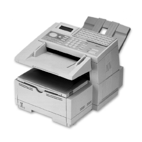
General Appearance Figure 1.4.1 shows the general appearance of the OKIFAX 5700/5900. Stacker-Document Operation Panel Tray-Document Tray-Paper Figure 1.4.1 General Appearance of OKIFAX 5700/5900 OKIFAX 5700/5900 1 - 9... - Page 16 Figure 1.4.2 Control Panel of OKIFAX 5700/5900 OKIFAX 5700/5900 1 - 10...
-
Page 17: Basic Performance Specifications
Basic Performance Specifications Table 1.5.1 shows basic performance specifications: Table 1.5.1 Basic Performance Specifications Item Specifications Applicable line 1) PSTN (Public switched telephone network) 2) PBX (Private branch exchange ) 3) ISDN (Integrated services digital network): Option 4) LAN (Local area network): Option Line interface 600 ohm balanced 1) Impedance... - Page 18 3) Weight, thickness and condition: Same as above Note: One single sheet should be loaded on the manual paper feeder for one occation. For best results use Oki Data recommended papers 1) Xerox 4200 (20-lb/75gm base weight paper) OKIFAX 5700/5900...
- Page 19 Item Specifications Recording paper cassette Up to 250 sheets/cassette First cassette (Oki Data recommended paper) Second cassette (option) Up to 500 sheets/cassette (Oki Data recommended paper) Effective recording paper Printing area Recording paper feeding direction 1) Printable area Printable area...
- Page 20 Item Specifications 2) Guaranteed printing area Guaranteed printing area 14 inch 13 inch Letter Size A4 Size Legal Size Legal Size inch inch inch inch 279.4 11.7 355.6 13 330.2 8.27 210 10.5 266.7 11.2 284.3 13.5 342.9 12.5 317.5 203.2 7.77 197.3 203.2...
- Page 21 “MSG. IN MEMORY”, and the Alarm LED turn on. Minimum scan line time for 0 ms, when receiving in ECM mode of from an Oki Data receiving facsimile. 5 ms at 15.4 line/mm or 7.7 line/mm and 10 ms at 3.85 line/ mm when receiving from a non-Oki Data facsimile or non- ECM mode.
- Page 22 The modem automatically selects transmission speed according to the line condition. Protocol 1) ITU-T Rec. T.30 2) Oki special protocol (speed protocol) The T.30 handshaking procedure will be conducted at message transmission speed instead of 300 baud, during transmission multi-page.
- Page 23 Item Specifications Image transmission time 2.5 seconds at 33.6 kbps with JBIG for OKIFAX 5900 and 3.0 seconds at 33.6 kbps for OKIFAX 5700 per sheet of ITU-T No.1 evaluation test chart. Note: This speed denotes the time interval correspond- ing to Phase C (message transmission phase) as referred to in ITU-T T.30.
- Page 24 Item Specifications Memory capacity (Image Basic model Optional memory memory) OKIFAX 5700 2.5 M-byte 2/4 M-byte OKIFAX 5900 4.5 M-byte 2/4 M-byte OKIFAX 5900 Memory OKIFAX 5700 condition [pages] Print Priority=OFF Print Priority=ON Standard (without option) With option 2 M-byte board 4 M-byte Note1: ITU-T No.1 sample document is used to count the...
- Page 25 Item Specifications ISDN G4 (option) The follwing four modes are supported. 1) G4 function 2) ISDN G4 communication 3) ISDN G3 communication 4) ISDN Report and List Note: For details, see appendix “ISDN G4 option sys- tem specifications”. Power supply unit and Power Power consumption of the machine (Typical power with- consumption of the machine out optional board)
- Page 26 Item Specifications Ambient condition Temperature and Humidity In operation Unit Power off mode During Storage Temperature 32 - 110 14 - 110 50 - 90 (0 - 43) (-10 - 43) ( C) (10 - 32) Humidity 10 - 90 10 -90 20 - 80 Maximum wet bulb...
-
Page 27: Reports And Lists
Reports and Lists Table 1.6.1 shows Report and Lists Specifications. Table 1.6.1 Report and Lists Specifications Item Specifications Active memory files This report will be manually or automatically printed out for information of transmission/reception data stored in the memory. When there is no stored image data in the memory at all, the Active memory files is not printed out. - Page 28 Item Specifications Power outage report If received communications are lost due to power failure, this report is printed out automatically at power recovery. The information printed on the Power outage report is not printed out on the Activity report. See Fig. 1-6-8 Confidential reception report This report will be informed operator about a stored confidential messages in the memory and automatically...
- Page 29 DATE TIME DISTANT STATION ID MODE PAGES 1 2 / 2 4 1 3 : 0 0 OKI DATA SYS-1 CALLING 1 2 / 2 4 1 2 : 0 3 OKI DATA SYS-2 CALLING 1 2 / 2 4...
- Page 30 ACTIVE MEMORY FILES P2 1 2 / 2 4 / 1 9 9 8 1 9 : 1 0 ID=ODS PERSONAL BOX BOX NO. MODE ENTRIES PAGES CONF CONF CONF CONF POLL POLL POLL POLL POLL POLL POLL POLL POLL POLL POLL POLL...
-
Page 31: Active Memory Files
DATE TIME DISTANT STATION ID MODE PAGES 1 2 / 2 4 1 3 : 0 0 OKI DATA SYS-1 CALLING 1 2 / 2 4 1 5 : 3 0 OKI DATA SYS-9 CALLING 1 2 / 2 4... -
Page 32: Activity Report
0 1 ’ 1 0 ” ODS FUKUSHIMA POLL=01 0000*7 1 2 / 2 4 1 3 : 0 0 0 1 ’ 0 0 ” OKI DATA SYS POLLED 0000 Confidential reception *2: Manual TX *3: Memory reception *4: Broadcast TX... -
Page 33: Message Confirmation
MESSAGE CONFIRMATION 12/24/1998 17:05 ID=OKI DATE S,R-TIME DISTANT STATION ID M OD E PAGES RESULT 1 2 / 2 4 0 ' 2 0 " 123456789012345678901234 CALLING 0000 IMAGE Fig. 1-6-3-1 Message Confirmation (When the transmission is normal end.) OKIFAX 5700/5900... - Page 34 MESSAGE CONFIRMATION Printed only when Error page 12/24/1998 17:05 ID=OKI DATE S.R-TIME DISTANT STATION ID MODE PAGES RESULT 1 2 / 2 4 0 ' 2 0 " 123456789012345678901234 CALLING 0000 POSSIBLE ERROR PAGE:*001*002 IMAGE Fig. 1-6-3-2 Message Confirmation (Error report)
- Page 35 (1) Title of the report (2) Date and time when the report was printed. (3) Sender ID (4) Total TX and total RX time (5) Date of transmission or reception (6) Time when the communication started (7) Length of time for which the OKIFAX 5700/5900 was connected to the line (8) Identification of the remote station •...
- Page 36 BROADCAST ENTRY REPORT P1 12/24/1998 17:04 ID=OKI TAKASAKI LOCATION ID LOCATION ID 1=1234567890123456789012345678901234567890 2=1234567890123456789012345678901234567890 3=OKI-SHIBAURA 4=OKI-SHIBAURA 5=FX-050 6=FX-175 7=FX-175VP-ENHANC 8=FX-056 9=OKIFAX450 10=OKIFAX460M 11=M125INTL 12=M125-US 13=OKIFAX5600 14=OKIFAX1050 15=OKIFAX1000 16=OKIFAX2200 17=OF-3GX 18=115AD 19=2275 20=OF-8 21=OF-18 22=OF-58H 23=M4200 24=5400 25=OF-2B 26=OF-1 27=OF-21 28=2127...
- Page 37 BROADCAST ENTRY REPORT P2 12/24/1998 17:04 ID=OKI TAKASAKI LOCATION ID KEYPAD 1234567890123456789012345678901234567890 1234567890123456789012345678901234567890 1234567890123456789012345678901234567890 1234567890123456789012345678901234567890 1234567890123456789012345678901234567890 1234567890123456789012345678901234567890 1234567890123456789012345678901234567890 1234567890123456789012345678901234567890 1234567890123456789012345678901234567890 1234567890123456789012345678901234567890 Fig. 1-6-4-2 Broadcast Entry Report for OKIFAX 5700 (2/2) OKIFAX 5700/5900 1 - 31...
- Page 38 BROADCAST ENTRY REPORT P1 12/24/1998 17:04 ID=OKI TAKASAKI LOCATION ID LOCATION ID 1=1234567890123456789012345678901234567890 2=1234567890123456789012345678901234567890 3=OKI-SHIBAURA 4=OKI-SHIBAURA 5=FX-050 6=FX-175 7=FX-175VP-ENHANC 8=FX-056 9=OKIFAX450 10=OKIFAX460M 11=M125INTL 12=M125-US 13=OKIFAX5600 14=OKIFAX1050 15=OKIFAX1000 16=OKIFAX2200 17=OF-3GX 18=115AD 19=2275 20=OF-8 21=OF-18 22=OF-58H 23=M4200 24=5400 25=OF-2B 26=OF-1 27=OF-21 28=2127...
- Page 39 159=KAI-SISYA-NOR 160=KAI-SISYA-SWE 161=KAI-SISYA-DEN 162=KAI-SISYA-GER 163=KAI-SISYA-TCH 164=KAI-SISYA-POL 165=KAI-SISYA-AUT 166=KAI-SISYA-BEL 167=KAI-SISYA-FRE 168=KAI-SISYA-ESP 169=KAI-SISYA-GRE 170=KAI-SISYA-AUS 171=KAI-SISYA-SIN 172=KAI-SISYA-HNG 173=OKI DATA USA 174=OKI DATA INTL 175=OKI DATA BGR 176=OKI DATA IRL 177=OKI DATA NOR 178=OKI DATA SWE 221=ABCDEFGHIJ12345 222=ABCDEFGHIJ23456 223=ABCDEFGHIJ34567 224=ABCDEFGHIJ45678 225=ABCDEFGHIJ56789 226=ABCDEFGHIJ67890 227=ABCDEFGHIJ78901 228=ABCDEFGHIJ89012...
-
Page 40: Broadcast Entry Report
BROADCAST ENTRY REPORT 12/24/1998 17:04 ID=OKI TAKASAKI LOCATION ID LOCATION ID 1=1234567890123456789012345678901234567890 50=1234567890123456789012345678901234567890 100=OKI-SHIBAURA KEYPAD 1234567890123456789012345678901234567890 1234567890123456789012345678901234567890 1234567890123456789012345678901234567890 1234567890123456789012345678901234567890 1234567890123456789012345678901234567890 1234567890123456789012345678901234567890 1234567890123456789012345678901234567890 1234567890123456789012345678901234567890 1234567890123456789012345678901234567890 1234567890123456789012345678901234567890 Fig. 1-6-4-5 Broadcast Entry Report (When the destination of Broadcast TX is specified by Speed Dial No.1, No.50, and No.100) - Page 41 START TIME = 12/24 17:22 TOTAL TIME = 1:22'22" LOCATION ID PAGES RESULT LOCATION ID PAGES RESULT 1=OKIDATA SYS1 2=OKI DATA SYS2 3=OKIDATA SYS3 4=OKI DATA SYS4 5=OKIDATA SYS5 6=OKI DATA SYS6 7=OKIDATA SYS7 8=OKI DATA SYS8 9=OKIDATA SYS9 10=OKI DATA SYS10...
- Page 42 BROADCAST CONFIRMATION REPORT P2 12/24/1998 19:22 ID=OKI LOCATION ID PAGES RESULT KEYPAD 123456789012345678901234 123456789012345678901234 123456789012345678901234 123456789012345678901234 123456789012345678901234 123456789012345678901234 123456789012345678901234 123456789012345678901234 123456789012345678901234 123456789012345678901234 Fig. 1-6-5-2 Broadcast Confirmation Report P2 for OKIFAX 5700 OKIFAX 5700/5900 1 - 36...
- Page 43 START TIME = 12/24 17:22 TOTAL TIME = 1:22'22" LOCATION ID PAGES RESULT LOCATION ID PAGES RESULT 1=OKIDATA SYS1 2=OKI DATA SYS2 3=OKIDATA SYS3 4=OKI DATA SYS4 5=OKIDATA SYS5 6=OKI DATA SYS6 7=OKIDATA SYS7 8=OKI DATA SYS8 9=OKIDATA SYS9 10=OKI DATA SYS10...
- Page 44 12/24/1998 19:22 ID=OKI LOCATION ID PAGES RESULT LOCATION ID PAGES RESULT 141=OKIDATA SYS141 142=OKI DATA SYS142 143=OKIDATA SYS143 144=OKI DATA SYS144 145=OKIDATA SYS145 146=OKI DATA SYS146 147=OKIDATA SYS147 148=OKI DATA SYS148 149=OKIDATA SYS149 150=OKI DATA SYS150 151=OKIDATA SYS151 152=OKI DATA SYS152...
-
Page 45: Broadcast Confirmation Report
19:22 ID=OKI PAGES = 001 START TIME = 12/24 17:22 TOTAL TIME = 1:22'22" LOCATION ID PAGES RESULT LOCATION ID PAGES RESULT 1=12345678901234567890 50=OKI DATA SYS2 100=OKIDATA SYS3 KEYPAD 123456789012345678901234 123456789012345678901234 123456789012345678901234 123456789012345678901234 123456789012345678901234 123456789012345678901234 123456789012345678901234 123456789012345678901234 123456789012345678901234 123456789012345678901234 Fig. 1-6-5-5 Broadcast Confirmation Report (When the destination of Broadcast TX is specified by Speed Dial No.1, No.50, and No.100) - Page 46 CONFIGURATION P1 12/24/1998 22:00 ID=ODC TAKASAKI USER FUNCTION SETUP MACHINE SETTINGS < 10 > AUTO ANSWER MODE < 11 > MONITOR VOLUME HIGH-MID. < 12 > BUZZER VOLUME L O W < 13 > USER LANGUAGE ENGLISH < 14 > REMOTE DIAGNOSIS <...
- Page 47 CONFIGURATION P2 12/24/1998 22:00 ID=ODC TAKASAKI USER FUNCTION SETUP REPORT OPTIONS < 70 > MCF. (SINGLE-LOC.) < 71 > MCF. (MULTI-LOC.) < 72 > MESSAGE IN MCF. < 73 > ERR. REPORT (MCF.) LAN OPTIONS < 80 > AUTO TRAY SW <...
-
Page 48: Technical Functions: Setup
CONFIGURATION P3 12/24/1998 22:00 ID=ODC TAKASAKI TECHNICAL FUNCTION SETUP < 01 > SERVICE BIT < 02 > MONITOR CONT. < 03 > COUNTRY CODE < 04 > TIME/DATE PRINT < 05 > TSI PRINT < 06 > TAD MODE TYPE2 <... - Page 49 CONFIGURATION P1 12/24/1998 22:00 ID=ODC TAKASAKI USER FUNCTION SETUP MACHINE SETTINGS < 10 > AUTO ANSWER MODE < 11 > MONITOR VOLUME HIGH-MID. < 12 > BUZZER VOLUME L O W < 13 > USER LANGUAGE ENGLISH < 14 > REMOTE DIAGNOSIS <...
- Page 50 CONFIGURATION P2 12/24/1998 22:00 ID=ODC TAKASAKI USER FUNCTION SETUP REPORT OPTIONS < 70 > MCF. (SINGLE-LOC.) < 71 > MCF. (MULTI-LOC.) < 72 > MESSAGE IN MCF. < 73 > ERR. REPORT (MCF.) TEL NO. FORWARDING NO. FORWARD ON P-ERR. = 6992 RELAY REPORT NO.
- Page 51 Note: *1: Printed only when Service Bit = ON. *2: When Service Bit = OFF, printed or not depending on the xpare bit. USER FUNCTION SETUP > MACHINE SETTINGS > No.26: POWER SAVE MODE is skipped at the time of COUNTRY CODE=USA of DEFAULT TYPE=1(ODA) regardless of the xpara bit. *3: Printed when the MFP option is specified in Mfpunlock setup.
- Page 52 TELEPHONE DIRECTORY P1 12/24/1998 17:05 ID=OKI LOCATION ID TEL NO G3-ECHO / G3-RATE / MODE 1 OKI DATA SYS1 LOC# 1234567890123456789012345678901234567890 33.6K ALT# 0101 2 OKI DATA SYS2 LOC# 0002 33.6K ALT# 0102 3 OKI DATA SYS3 LOC# 0003 33.6K...
- Page 53 12/24/1998 17:05 ID=OKI LOCATION ID TEL NO G3-ECHO / G3-RATE MODE 31 OKI DATA SYS31 LOC# 1234567890123456789012345678901234567890 [ 1 2 : 1 2 ] 33.6K ALT# 0010 32 OKI DATA SYS32 LOC# 0010 [ 1 2 : 1 2 ] 33.6K...
- Page 54 TELEPHONE DIRECTORY P3 12/24/1998 17:05 ID=OKI LOCATION ID TEL NO G3-ECHO / G3-RATE MODE 61 OKI DATA SYS61 LOC# 1234567890123456789012345678901234567890 33.6K 62 OKI DATA SYS62 LOC# 0002 33.6K 63 OKI DATA SYS63 LOC# 0003 33.6K 64 OKI DATA SYS64 LOC# 0004 33.6K...
- Page 55 TELEPHONE DIRECTORY P4 12/24/1998 17:05 ID=OKI LOCATION ID TEL NO G3-ECHO / G3-RATE MODE 91 OKI DATA SYS91 LOC# 1234567890123456789012345678901234567890 33.6K 92 OKI DATA SYS92 LOC# 0002 33.6K 93 OKI DATA SYS93 LOC# 0003 33.6K 94 OKI DATA SYS94 LOC# 0004 33.6K...
- Page 56 TELEPHONE DIRECTORY P5 12/24/1998 17:05 ID=OKI LOCATION ID TEL NO G3-ECHO / G3-RATE MODE 121 OKI DATA SYS121 LOC# 1234567890123456789012345678901234567890 33.6K 122 OKI DATA SYS122 LOC# 0002 33.6K 123 OKI DATA SYS123 LOC# 0003 33.6K 124 OKI DATA SYS124 LOC# 0004 33.6K...
- Page 57 TELEPHONE DIRECTORY P1 12/24/1998 17:05 ID=OKI LOCATION ID TEL NO G3-ECHO / G3-RATE / MODE 1 OKI DATA SYS1 LOC# 1234567890123456789012345678901234567890 33.6K ALT# 0101 2 OKI DATA SYS2 LOC# 0002 33.6K ALT# 0102 3 OKI DATA SYS3 LOC# 0003 33.6K...
- Page 58 12/24/1998 17:05 ID=OKI LOCATION ID TEL NO G3-ECHO / G3-RATE MODE 31 OKI DATA SYS31 LOC# 1234567890123456789012345678901234567890 [ 1 2 : 1 2 ] 33.6K ALT# 0010 32 OKI DATA SYS32 LOC# 0010 [ 1 2 : 1 2 ] 33.6K...
- Page 59 TELEPHONE DIRECTORY P3 12/24/1998 17:05 ID=OKI LOCATION ID TEL NO G3-ECHO / G3-RATE MODE 61 OKI DATA SYS61 LOC# 1234567890123456789012345678901234567890 33.6K ALT# 0010 62 OKI DATA SYS62 LOC# 0002 33.6K ALT# 0010 63 OKI DATA SYS63 LOC# 0003 33.6K ALT# 0010...
- Page 60 TELEPHONE DIRECTORY P4 12/24/1998 17:05 ID=OKI LOCATION ID TEL NO G3-ECHO / G3-RATE MODE 91 OKI DATA SYS91 LOC# 1234567890123456789012345678901234567890 33.6K 92 OKI DATA SYS92 LOC# 0002 33.6K 93 OKI DATA SYS93 LOC# 0003 33.6K 94 OKI DATA SYS94 LOC# 0004 33.6K...
- Page 61 TELEPHONE DIRECTORY P5 12/24/1998 17:05 ID=OKI LOCATION ID TEL NO G3-ECHO / G3-RATE MODE 121 OKI DATA SYS121 LOC# 1234567890123456789012345678901234567890 33.6K 122 OKI DATA SYS122 LOC# 0002 33.6K 123 OKI DATA SYS123 LOC# 0003 33.6K 124 OKI DATA SYS124 LOC# 0004 33.6K...
- Page 62 TELEPHONE DIRECTORY P6 12/24/1998 17:05 ID=OKI LOCATION ID TEL NO G3-ECHO / G3-RATE MODE 151 OKI DATA SYS151 LOC# 1234567890123456789012345678901234567890 33.6K 152 OKI DATA SYS152 LOC# 0002 33.6K 153 OKI DATA SYS153 LOC# 0003 33.6K 154 OKI DATA SYS154 LOC# 0004 33.6K...
- Page 63 TELEPHONE DIRECTORY P7 12/24/1998 17:05 ID=OKI LOCATION ID TEL NO G3-ECHO / G3-RATE MODE 181 OKI DATA SYS181 LOC# 1234567890123456789012345678901234567890 33.6K 182 OKI DATA SYS182 LOC# 0002 33.6K 183 OKI DATA SYS183 LOC# 0003 33.6K 184 OKI DATA SYS184 LOC# 0004 33.6K...
- Page 64 TELEPHONE DIRECTORY P8 12/24/1998 17:05 ID=OKI LOCATION ID TEL NO G3-ECHO / G3-RATE MODE 211 OKI DATA SYS211 LOC# 1234567890123456789012345678901234567890 33.6K 212 OKI DATA SYS212 LOC# 0002 33.6K 213 OKI DATA SYS213 LOC# 0003 33.6K 214 OKI DATA SYS214 LOC# 0004 33.6K...
-
Page 65: Telephone Directory
TELEPHONE DIRECTORY 12/24/1998 17:05 ID=OKI LOCATION ID TEL NO G3-ECHO / G3-RATE MODE 1 OKI DATA SYS1 LOC# 1234567890123456789012345678901234567890 33.6K ALT# 0101 50 OKI DATA SYS50 LOC# 0002 33.6K 100 OKI DATA SYS100 LOC# 0003 33.6K Fig. 1-6-7-14 Telephone Directory (When the destination is registered by Speed Dial No.1, No.50, and No.100 only.) -
Page 66: Power Outage Report
1 0 : 3 0 ODS TAKASAKI LOST 1 2 / 2 4 1 2 : 0 5 0 1 ' 2 0 " OKI FAX CONF=01 LOST 0000 1 2 / 2 4 1 3 : 0 0 0 0 ' 2 0 "... -
Page 67: Confidential Rx Report
CONFIDENTIAL RX REPORT 12/24/1998 17:05 ID=OKI DATE S,R-TIME DISTANT STATION ID M O D E PAGES RESULT 1 2 / 2 4 0 1 ' 3 0 " 123456789012345678901234 CONF=01 0000 Fig. 1-6-9 Confidential RX Report (1) Title of the report (2) Date and time when the report was printed. - Page 68 PROTOCOL DUMP P1 12/24/1998 19:00 ID=OKI TAKASAKI DATE TIME S.R-TIME DISTANT STATION ID M O D E PAGES RESULT 1 2 / 2 4 1 8 : 5 6 0 0 ' 3 3 " 123456789012345678901234 CALLING 0000 PPS_MPS PPS_PRI_EOP...
- Page 69 PROTOCOL DUMP P2 12/24/1998 19:00 ID=OKI TAKASAKI RECEIVED FRAME CSI/CIG/TSI SEP/SUB Fig. 1-6-10-2 Protocol Dump P2 (G3) (1) Title of the report (2) Date and time when the report was printed (3) Sender ID (4) Date of communication (5) Time of communication...
-
Page 70: Self Diagnosis Report
SELF DIAGNOSIS REPORT 12/24/1998 12:00 ID=0dc Takasaki MAIN BOARD CPU-ROM VERSION aaaa HASH hhhh CPU-RAM PROGRAM1 VERSION aaaa HASH hhhh PROGRAM2 VERSION aaaa HASH hhhh LANGUAGE VERSION aaaa HASH hhhh DEFAULT VERSION aaaa HASH hhhh DEFAULT TYPE M O D E M VERSION hhhh RAM1... - Page 71 SELF DIAGNOSIS REPORT 12/24/1998 12:00 ID=0dc Takasaki MAIN BOARD CPU-ROM VERSION aaaa HASH hhhh CPU-RAM PROGRAM1 VERSION aaaa HASH hhhh PROGRAM2 VERSION aaaa HASH hhhh LANGUAGE VERSION aaaa HASH hhhh DEFAULT VERSION aaaa HASH hhhh DEFAULT TYPE M O D E M VERSION hhhh RAM1...
- Page 72 Note: *1: a indicates an alphanumeric character; n indicates a numeric character (0 to 9); h indicates a hexadecimal number; and b indicates 0 or 1. *2: Printed when the option memory board is mounted and if not, entry lines following this line are not omitted.
- Page 73 12/24/1998 18:15 DATA/TIME 12/24/1998 13:32 EXEC TSK PROMIS TSKNO : NGNO 0004 FLASH COUNT : 00000067 MSGDATA TSKDATA 01 00 01 01 02 03 04 05 01 01 01 01 01 01 01 01 01 01 01 10 01 00 01 01 02 03 04 05 01 01 01 01 01 01 01 01 01 01 01 10 01 00 01 01 02 03 04 05 01 01 01 01 01 01 01 01 01 01 01 10...
- Page 74 FUNCTION LIST P1 12/24/1998 22:00 ID=0dc Takasaki TO ACCESS PROGRAM MENU ITEMS: -PRESS THE MENU KEY -TO LOCATE A MENU ITEM. USE THE UP-DOWN ARROW KEY -SELECT THE MENU ITEM USING EITHER THE ENTER OR RIGHT ARROW KEYS TO QUICKLY ACCESS A SPECIFIC "SETUP" ITEM: -PRESS THE MENU KEY -ENTER THE TWO-DIGIT NUMBER OF THE SETUP ITEM ON THE TEN KEY PAD MENU...
- Page 75 FUNCTION LIST P2 12/24/1998 22:00 ID=0dc Takasaki MENU SETUP MACHINE SETTINGS < 10 > AUTO ANSWER MODE FAX/TEL/TF/TAD/MEM/PC/FWD * 1 1 < 11 > MONITOR VOLUME SELECT FROM 5 SOUND LEVEL < 12 > BUZZER VOLUME SELECT FROM 4 SOUND LEVEL <...
- Page 76 FUNCTION LIST P3 12/24/1998 22:00 ID=0dc Takasaki MENU SETUP REPORT OPTIONS < 70 > MCF. (SINGLE-LOC.) ON/OFF < 71 > MCF. (MULTI-LOC.) ON/OFF < 72 > MESSAGE IN MCF. ON/OFF < 73 > ERR. REPORT (MCF.) ON/OFF LAN OPTIONS < 80 > AUTO TRAY SW ON/OFF <...
- Page 77 FUNCTION LIST P1 12/24/1998 22:00 ID=0dc Takasaki STEP ACCESSING TO THE WANTED ITEM: -PRESS THE MENU KEY -CHOOSE THE ITEM WITH THE UP-DOWN KEY -DECIDE THE CHOSEN ITEM WITH THE ENTER or RIGHT KEY SPEED ACCESSING TO THE WANTED ITEM: =PRESS THE MENU KEY -ENTER THE NUMBER OF THE ITEM MENU...
- Page 78 FUNCTION LIST P2 12/24/1998 22:00 ID=0dc Takasaki MENU SETUP MACHINE SETTINGS < 10 > AUTO ANSWER MODE FAX/TEL/MEM/PC/FWD * 1 1 < 11 > MONITOR VOLUME SELECT FROM 5 SOUND LEVEL < 12 > BUZZER VOLUME SELECT FROM 3 SOUND LEVEL <...
- Page 79 FUNCTION LIST P3 12/24/1998 22:00 ID=0dc Takasaki MENU SETUP REPORT OPTIONS < 70 > MCF. (SINGLE-LOC.) ON/OFF < 71 > MCF. (MULTI-LOC.) ON/OFF < 72 > MESSAGE IN MCF. ON/OFF < 73 > ERR. REPORT (MCF.) ON/OFF COUNTER DRUM COUNT PRINT COUNT SCAN COUNT PRINTER CLEANING...
- Page 80 Note: *1: Printed only when Service Bit = ON. *2: When Service Bit = OFF, printed or not depending on the xpare bit. USER FUNCTION SETUP > MACHINE SETTINGS > No.26: POWER SAVE MODE is skipped at the time of COUNTRY CODE=USA of DEFAULT TYPE=1(ODA) regardless of *the xpara bit. •3: Printed when the MFP option is specified in Mfpunlock setup.
-
Page 81: Group Directory
GROUP DIRECTORY 12/24/1998 17:04 ID=OKI TAKASAKI GROUP NO. #1=OKI DATA SYS1 LOCATION ID LOCATION ID 1 = 1234567890123456789012345678901234567890 2 = 1234567890123456789012345678901234567890 3 = OKI-SHIBAURA 4 = OKI-SHIBAURA 5 = FX-050 6 = FX-175 7 = FX-0175VP-ENHANC 8 = FX-056 9 = OKIFAX450... - Page 82 GROUP DIRECTORY P1 12/24/1998 17:04 ID=OKI TAKASAKI GROUP NO. #1=OKI DATA SYS1 LOCATION ID LOCATION ID 1 = 1234567890123456789012345678901234567890 2 = 1234567890123456789012345678901234567890 3 = OKI-SHIBAURA 4 = OKI-SHIBAURA 5 = FX-050 6 = FX-175 7 = FX-0175VP-ENHANC 8 = FX-056...
- Page 83 GROUP DIRECTORY P2 12/24/1998 17:04 ID=OKI TAKASAKI GROUP NO. #1=OKI DATA SYS1 LOCATION ID LOCATION ID 141 = KAI-EIGYOU-INTL 142 = KAI-EIGYOU-GBR 143 = KAI-EIGYOU-NOR 144 = KAI-EIGYOU-SWE 145 = KAI-EIGYOU-DEN 146 = KAI-EIGYOU-GER 147 = KAI-EIGYOU-TCH 148 = KAI-EIGYOU-POL...
- Page 84 GROUP DIRECTORY 12/24/1998 17:04 ID=OKI TAKASAKI GROUP NO. #1=OKI DATA SYS1 LOCATION ID LOCATION ID 1 = 1234567890123456789012345678901234567890 50 = 1234567890123456789012345678901234567890 100 = OKI-SHIBAURA Fig. 1-6-14-4 Group Directory (When the destination of Speed Dial No.1, No.50, and No.100 is selected by the group destination.)
- Page 85 PROTOCOL DUMP P1 12/24/1998 19:00 ID=OKI TAKASAKI DATE TIME S,R-TIME DISTANT STATION ID M O D E PAGES RESULT 1 2 / 2 4 1 8 : 5 6 0 0 ' 3 3 " OKI SHIBAURA CALLING-G4 0000 DCH.
- Page 86 PROTOCOL DUMP P2 12/24/1998 19:00 ID=OKI TAKASAKI CR/CN 00 00 00 00 00 00 00 00 00 00 00 00 00 00 00 00 00 00 00 00 00 00 00 00 00 00 00 00 00 00 00 00...
-
Page 87: (18) Setup
(1) Title of the report (2) Date and time when the report was printed (3) Sender ID (4) Date of communication (5) Time of communication (6) One message transmission/reception time (7) Identification of remote station • CSI and/or telephone number (8) Mode of transmission/reception according to ITU-T designation (9) Total number of pages in communication (10) Identification of the result of the communication... -
Page 88: Nic Configuration
NIC CONFIGURATION 24/12/1998 19:00 ID=OKI Takasaki MLETB07 Version 1.0.1 TCP/IP status IP address : 192.168.1.21 Subnet Mask : 255.255.255.0 Gateway addr: 192.168.1.254 NetWare status NWPrint mode: Failed EtherTalk status Zone Name Type Name : LaserWriter Object Name : ML1E4048 MAC Address : 00:80:92:1E:40:48 Fig. - Page 89 * * * * * * * * * * * * * * * * * * * * * * * * * * * * * * * * * * * * * * * * * * * * * * * * * * * * * * * * * * * * * * * * * * * * * * * * * * * * * * * * * *User name: SUPERVISOR(2) Queue:...
- Page 90 CHAPTER 2 INSTALLATION PROCEDURE...
-
Page 91: General
Setup Information General The following flowchart outlines the installation procedure. Site selection (See 2.2) Unpacking (See 2.3) Contents identification (See 2.4) Installation of attachments (See 2.5) AC cord connection (See 2.6) Telephone and line connection (See 2.7) Packing for shipment (See 2.8) General procedure key operation (See 2.9.1) - Page 92 Clock adjustment (See 2.9.5.1) ID/Password programming (See 2.9.5.2) Machine settings (See 2.9.5.3) Dialing options (See 2.9.5.4) Incoming options (See 2.9.5.5) Report options (See 2.9.5.6) LAN options (See 2.9.5.7) Table: User Default setting (See 2.9.6) Table: Technical default setting (See 2.9.7) Table: Dial parameter default setting (See 2.9.8) Off-line tests...
- Page 93 Site Selection INSTALLATION Precautions for Installation (1) Fluctuation in line voltage • 120VAC (102V to 127V) • 230VAC (198V to 264V) (2) Room temperature • 50 to 90°F (10 to 32°C) (3) Humidity • 20 to 80% RH (4) Operating environment •...
- Page 94 Document exit Document Paper exit (face down) Paper exit (face up) Recording paper cassette Paper 11.81" 19.69" (300mm) (500mm) Note: *1: This space necessary for having the telephone set. *2: This space is necessary for removing the recording paper cassette. *3: This space is necessary for installing the document stacker and allow space for the fan exhaust.
- Page 95 Unpacking Procedure (1) Remove the on the top of the carton box and open its cover. External carton box Packing tape Packing tape Carton label Figure 2.3.1 Unpacking Procedure (1) (2) Take out the accessory box from the carton box. (See figure 2.3.2) (3) Take out the machine with plastic wrapper from the box.
- Page 96 Box-Accessories Connecting Codes Toner Cartrige Stacker Document OKIFAX 5700/5900 Pad-Assy (L) 40932401 Pat-Assy (R) 40932402 Box-Individual Bar Code Figure 2.3.2 Unpacking Procedure (2) OKIFAX 5700/5900 2 - 6...
- Page 97 Contents Identification After having taken out the machine and accompainied accessaries from the carton box, check the contents according to the following list. Table 2.4.1 Contents List Item No. Name Q’ty Remarks OKIFAX 5700/5900 facsimile AC power cord I/D unit Already installed.
- Page 98 Installation of Attachments (1) Items • Image Drum (ID) Unit (already installed) • Toner cartridge • Recording paper • Document stacker (2) Procedure 1) Toner cartridge • Peel off the fixed tape attached to the tray-paper. • Open the tray-document and tray-paper. Figure 2.5.1 Toner Cartridge Installation (1) •...
- Page 99 • Take out the toner cartridge from the damp proof bag, shake it five or six times as shown in the illustration to eliminate the toner deflection, and peel off the seal genitly. Seal Toner cartridge Figure 2.5.3 Toner Cartridge Installation (3) •...
- Page 100 • Press the gray lever forward until it stops. Figure 2.5.5 Toner Cartridge Installation (5) • Clean the toner scattered in the vicinity of the toner cartridge using a cloth moistened with cold water. Do not use hot water since it makes the toner stick there. •...
- Page 101 2)Recording paper Note: About 250 sheets of the new paper can be set in the recording paper cassette. • Remove the paper cassette from the facsimile by pulling the cassette tab. • Sheets must not exceed the paper full marker of the new paper limit indication. If excessive sheets are set, it will cause paper jams.
- Page 102 3) Document stacker • Hang the document stacker onto hanging position. OKIFAX 5700/5900 2 - 12...
- Page 103 AC Cord Connection The power supply is provided as follows: Normal input voltage 120VAC (Voltage range 102 to 127VAC) Normal input voltage 230VAC (Voltage range 198 to 250VAC) Check whether the AC voltage of your input is within the above-mentioned voltage range and if so, check that the power switch is turned OFF.
- Page 104 Telephone and Line Connection (1) Procedure • Connect the lines. Exchange line External telephone cable Packing for Shipment Caution: When packing the OKIFAX 5700/5900 for shipment, REMOVE THE IMAGE DRUM AND TONER FROM THE UNIT AND SHIP SEPARATELY! Failure to do this will result in damage to the machine. OKIFAX 5700/5900 2 - 14...
-
Page 105: B. Programming And Initial Settings
Programming and Initial Settings Initial Settings 2.9.1 General Procedure of Key Operation Note: The fonts displayed on the LCD operation panel may differ from the fonts written this manual. Accessing to desired functions: • There are two methods for accessing a desired function: Step access and Speed access (direct access). - Page 106 User functions MENU Delayed TX Note: Delayed Batch TX Options preceded by a number in permit speed access. Priority TX Other options do not permit speed access. Confidential TX Relayinitiate TX Polling TX/RX Polling TX Bulletin Poll (BOX) Memory Poll Memory Poll (BULL) Feeder Poll Polling RX...
- Page 107 Machine Settings Auto Answer Mode Monitor Volume Buzzer Volume User Language Remote Diagnosis Tx Mode Default No Toner Mem. Rx Mem. Full Save Instant Dial Restrict Access ECM Function Closed Network Tone Save Sender ID 1'st Paper Size 2'nd Paper Size Power Save Mode ISDN Dial Mode Speech Receive...
- Page 108 Report Options MCF (Single-Loc.) MCF (Multi-Loc.) Image in MCF. Err. Report (MCF.) LAN Options AUTO TRAY SW. PAPER SIZE CHECK LAN PRINT T.O. IP ADDRESS SUBNET MASK DEFAULT GATEWAY Counter ( Service bit = ON), (Service bit = OFF & Toner Counter Clear = ON), ( Service bit = OFF &...
- Page 109 MENU RESOLUTION key x 2 Local Test Self Diagnosis Sens. Calibration LED Test Tone Send Test Modem Send Test Modem Rec. Test MF(Tone) Test Tone(T/F) Test LOOP BACK 1 LOOP BACK 2 INFO0 SENDING INFO1 SENDING INFO3 SENDING PULSE (1KHZ) SEND PULSE (2KHZ) SEND PULSE (N2KHZ) SEND Setup...
- Page 110 System Reset All Data CLR Location Data CLR Config. Data CLR Default Type Set PC Loading G4 PC Loading OKIFAX 5700/5900 2 - 20...
- Page 111 2.9.2 Technical Functions: Setup 1. This section explains items generally conducted by service personnel, not by users. (1) Step access 1) The machine is standby state with no document. 2) Press the MENU/EXIT key once. 3) Press the RESOLUTION key twice. The display will be shown the “TECHNICAL PRG.”.
- Page 112 2.9.2.1 Technical Functions Operation 1 Select Menu is shown as below: 1. Local Test 2. Technical Setup: Go to Section 2.9.2.2 3. System Reset 4. Default Type Set 5. PC Loading 6. G4 PC Loading M E N U 6 P O L L I N G T X / R X 7 >...
- Page 113 2.9.2.2 Technical Functions Operation 2 Setup 01: Service Bit (OFF/ON) 02: Monitor Cont. (OFF/ON) 03: Country Code (selecting the country code) 04: Time/Date Print (OFF/ONCE/ALL) 05: TSI Print (OFF/ON) 06: TAD Mode (OFF/TYPE1/TYPE2/TYPE3) 07: Real Time Dial (OFF/TYPE1/TYPE2) 08: TEL/FAX Switch (OFF/ON) 09: MDY/DMY (Month/Day/Year or Day/Month/Year)
- Page 114 T E C H N I C A L P R G . T E C H N I C A L P R G . X X <Speed Access> 1 L O C A L T E S T 1 >...
- Page 115 <Speed Access> ENTER/ S E T U P 0 8 T E L / F A X S W I T C H "08" 0 7 R E A L T I M E D I A L > O F F 0 8 >...
- Page 116 <Speed Access> ENTER/ "15" S E T U P 2.9.2.2.2 T1(RX) TIMER VALUE 1 4 T 1 ( T X ) T I M E R V A L U E 1 5 > T 1 ( R X ) T I M E R V A L U E 1 6 T 2 T I M E R * 1 0 0 M S ENTER/ "16"...
- Page 117 <Speed Access> ENTER/ "22" S E T U P 2.9.2.2.6 T/F TONE ATT. 2 1 A T T E N U A T O R 2 2 > T / F T O N E A T T . 2 3 M F A T T . ENTER/ S E T U P "23"...
- Page 118 <Speed Access> ENTER/ "29" S E T U P 2 9 V 3 4 T X R E T R Y 2 8 T R L A T C H C U R R E N T > O F F 2 9 >...
- Page 119 <Speed Access> ENTER/ S E T U P 3 6 J B I G F A C I L I T Y "36" 3 5 P R I N T P R I O R I T Y > O F F 3 6 >...
-
Page 120: T1 (Tx) Timer Value
2.9.2.2.1 T1 (TX) Timer Value Set the T1 timer (call connection wait time: XTTO) for transmission. S E T U P T E C H N I C A L P R G . 1 4 1 3 H / M O D E M R A T E 1 >... -
Page 121: T1 (Rx) Timer Value
2.9.2.2.2 T1 (RX) Timer Value Set the T1 timer for reception. The time from issue of the first DIS to issue of a signal is checked. If a time-out occurs, the line is disconnected. S E T U P T E C H N I C A L P R G . 1 5 1 4 T 1 ( T X ) T I M E R V A L U E 1 >... - Page 122 2.9.2.2.3 T2 Timer *100ms Registers the time duration (in seconds) for which the fax detects the EOL interval during reception of phase C. The fax disconnects the line when EOL cannot detect within T2 Timer. S E T U P T E C H N I C A L P R G .
- Page 123 2.9.2.2.4 Error Criterion Registers the threshould value whether to transmit RTN or MCF signal when the error occurs in received data. S E T U P T E C H N I C A L P R G . 1 8 1 7 D I S B I T 3 2 1 >...
- Page 124 2.9.2.2.6 T/F Tone Att. Adjusts the attenuation (dB) for the quasi-ring back tone send signal of TEL/FAX switching. Adjusting value is 0 to 15dB in one dB steps. S E T U P T E C H N I C A L P R G . 2 2 2 1 A T T E N U A T O R 1 >...
- Page 125 2.9.2.2.8 Ring Dura. *10ms Selects the minimum ring detection time to meet country's requirements. Adjusting time is 100MS to 990MS in 10MS steps. S E T U P T E C H N I C A L P R G . 2 4 2 3 M F A T T .
-
Page 126: Led Headstrobe
2.9.2.2.10 LED Headstrobe Setting of LED print head strobe signals (00000 - 11111). Selection of strobe sidth in LED head. "00000" is lightest and "11111" is darkest. S E T U P T E C H N I C A L P R G . 2 6 2 5 C M L T I M I N G * 1 0 0 M S 1 >... - Page 127 2.9.2.3 Technical Functions (Setup) • Table 2.9.2.3 shows the initial setting items and their purpose. (The default setting is different by the individual countries.) • Each item can be accessed by entering it on Technical Setup. • The detailed procedures of the initial setting items will be explained on the following tables.
- Page 128 Table 2.9.2.3 Technical Functions: Setup (2/11) Item Specifications Time and date print Determine whether the date and time set on the local machine are to be printed at the beginning of the re- ceived image. 1) Setting values OFF/ONCE/ALL selectable. OFF: Not printed ONCE: Printed on page 1 only...
- Page 129 Table 2.9.2.3 Technical Functions: Setup (3/11) Item Specifications TAD mode (For external tele- Switches between TAD modes. phone answering device.) This setting is required to determine whether TAD is to be selected in the AUTO ANSWER mode and set the fax operation to be performed after completion of TAD-side operation (response).
- Page 130 Table 2.9.2.3 Technical Functions: Setup (4/11) Item Specifications TEL/FAX switching Determine whether the TEL/FAX mode can be selected in the AUTO ANSWER mode. 1) Setting values Selective OFF: Not selective * When OFF is selected in the TEL/FAX mode, the FAX mode will be selected automatically.
- Page 131 Table 2.9.2.3 Technical Functions: Setup (5/11) Item Specifications MH only Determine whether only MH coding is to be handled forcibly. Switches the function of limiting the image compression to MH codes only. This setting is required when the line noise affects the received image.
- Page 132 Table 2.9.2.3 Technical Functions: Setup (6/11) Item Specifications DIS bit32 Determine whether the thirty-second bit (expansion bit) of DIS is to be sent out. 1) Setting values ON: Transmits a bit32 and a successing bit 32. OFF: Not transmit * When OFF is selected, machines of other compa- nies cannot receive documents in the EX.FINE, SEP/SUB mode or JBIG.
- Page 133 Table 2.9.2.3 Technical Functions: Setup (7/11) Item Specifications Attenuator Set the FAX signal attenuator (level). • Since the maximum send signal power level (dB) of the fax is at 0dB, you can select 0dB to -15dB in one dB steps for the send signal power level. 1) Setting values 0-15 dB se;ectable (in 1 dB steps): except FRE FRE: 7-15dB...
- Page 134 Table 2.9.2.3 Technical Functions: Setup (8/11) Item Specifications LED head strobe Set the LED head strobe time. The larger the value, the darker the image. 1) Setting values 00000 to 11111 (5 bits) Note1: When the rank marking of the new replaced LED print head (new part) is same as that of the old used LED print head (old part), you do not always have to set the LED print head strobe signal.
- Page 135 Relay initiate transmission operation cannot be performed. * If REMOTE DIAGNOSIS is set to ON although NSF Switch (this setting) is set to OFF, an NSF is sent and sent immediately if Oki’s original function is ON (confidential, etc.). OKIFAX 5700/5900 2 - 45...
- Page 136 Table 2.9.2.3 Technical Functions: Setup (10/11) Item Specifications ID/TSI priority Determines whether the personal ID or TSI is given priority during LCD display and printing. 1) Setting values Personal ID is given priority TSI: TSI is given priority ID/TSI PRIORITY=ID ID/TSI PRIORITY=TSI LCD display during LCD display during...
- Page 137 Table 2.9.2.3 Technical Functions: Setup (11/11) Item Specifications Print priority Determine whether the memory is mainly used for printing. This setting is required to rescue the image data that cannot be stored in the page memory if ACC compres- sion is carried out during PC/LAN printing. 1) Setting values Relationships between settings and page memory capacities are as follows:...
- Page 138 2.9.2.4 TEL/FAX automatic switching This function is used for the purpose of TEL/FAX automatic switching as follows. 1) If the machine detects a call with a CNG signal indicating an auto send facsimile call, it starts an automatic document receiving operation. 2) If machine detects a call without a CNG signal, machine generates the buzzer sounds as a telephone call.
- Page 139 (20/35 sec) LIFT HANDSET PRESS STOP TO CANCEL Load document NSF, CSI, DIS Press START Button AUTO REC. START Manual OKI TOKYO Transmission PAGE 001 RECEIVING G3/33.6K CML"OFF" 1 sec 1 sec 3.2 sec To detect CNG signal Notes *1: Ring Back Tone — 1 sec. ON, 3.2 sec. OFF *2: When you want to talk by phone, pick up handset.
- Page 140 2.9.2.5 TAD mode • TAD: Telephone Answering Device • TAD can be connected to extenal telephone terminal to record your messages. • TAD records your speech and switches an automatic voice message response to the calling station. Note1: A choice of TAD mode is available by technical Function (Setup No.06). Note2: The predetermined time is selectable between 20 or 30 sec.
- Page 141 • TAD mode flow chart 1) In case of TYPE2: If the fax does not CNG signal during working of TAD, the fax will go to standby state. 2) In case of TYPE 3: The fax does not detect CNG signal during 15 seconds from TAD operation starting. The fax starts CNG signal detection after 15 seconds from TAD operation.
- Page 142 2.9.2.6 Outline of Parallel Pick Up Parallel pick up is a function that controls a fax (to make a fax in receive mode) from a telephone set connected parallel to a fax. The two possible parallel connections of telephone sets A and B are shown in the figure. Remote control FAX (OKIFAX 5700/5900 etc.) To Modem...
- Page 143 (1/2) TEL1 S1.1~2 OFF-HOOK TEL2 Detector (2/2) I SW S1 - 3~6 Ring Detector " Impedance C31 R590 matching CN15 ~ Loop CN45 Current Detection MUTE LINE , AR arresters to Modem MF 2-digit Receiving special code CML: ON sensitivity MUTE circuit...
- Page 144 2.9.3 User’s Functions This section explains the items usually set up by general users. • Select Menu is shown as below: 1. Delayed TX 2. Delayed Batch TX 3. Priotity TX 4. Confidential TX 5. Relayinitiate TX 6. Polling TX/RX 7.
- Page 145 Menu selection 1 2 : 0 0 F A X 1 0 / 0 1 / 1 9 9 8 1 2 : 0 0 T E L Document on hopper S E L E C T L O C A T I O N ( S ) M E M O R Y F R E E 1 0 0 % O R P R E S S C O P Y MENU Key...
- Page 146 2.9.4 Location Program 1) The machine is standby state with no document. 2) Press the MENUEXIT key once. 3) Press the SHIFT DOWN ( ) key two times. 4) The menu option “9 LOCATION PROGRAM” indicated by the blinking cursor is se- lected, and press the ENTER/SHIFT RIGHT ( ) key.
-
Page 147: Location Program
Location Program M E M U 8 R E P O R T P R I N T 9 > L O C A T I O N P R O G R A M 1 0 S E T U P ENTER/ L O C A T I O N P R O G R A M ENTER/... - Page 148 Table 2.9.4.1 Location Program (1/2) Item Specifications Speed Dial Register speed dial number. (LOC#/NAME/ALT#/Communication parameters) * Only LOC# may be registered. (If NAME is omitted, location search will not be made.) 1) Number of speed dials OKIFAX 5700: 1-140 (1-40 are assigned to ONE TOUCH keys.) OKIFAX 5900: 1-230 (1-80 are assigned to ONE TOUCH keys.)
- Page 149 Table 2.9.4.1 Location Program (2/2) Item Specifications Batch TX time Set a batch transmission time (24-hour system). When a time is specified, locations can be specified during batch transmission operation. 1) Number of batch TX times that can be registered OKIFAX 5700/5900: 10 (Speed dial numbers 31-40 are assigned.) * Registration is enabled if the specified speed dial...
- Page 150 2.9.5 Setup 1) The machine is standby state with no document. 2) Press the MENU key once. 3) Press the SHIFT DOWN ( ) key three times. 4) The menu option “10 SETUP” indicated by the blinking cursor is selected, and press the ENTER/SHIFT RIGHT ( ) key.
- Page 151 M E N U 9 L O C A T I O N P R O G R A M 1 0 > S E T U P 1 1 C O U N T E R ENTER/ S E T U P ENTER/ 1 >...
-
Page 152: Clock Adjustment
2.9.5.1 Clock Adjustment <Speed Access> S E T U P M E N U 1 > C L O C K A D J U S T M E N T 6 P O L L I N G T X / R X 2 I D / P A S S W O R D P R G . -
Page 153: Id/Passward Programming:
2.9.5.2 ID/Passward Programming: 01. TSI/CSI 02. Sender ID 03. Personal Box 04. Mem. Password 05. Restrict ID 06. ISDN TID (Country Code/ISDN No./ISDN ID) 07. ISDN Sub No. <Speed Access> S E T U P M E N U 1 C L O C K A D J U S T M E N T 6 P O L L I N G T X / R X 2 >... -
Page 154: Tsi/Csi
2.9.5.2.1 TSI/CSI This function is used to register TSI/CSI. <Speed Access> I D / P A S S W O R D P R G . M E N U 0 1 0 1 > T S I / C S I 6 P O L L I N G T X / / R X 0 2 S E N D E R I D 7 >... -
Page 155: Sender Id
2.9.5.2.2 Sender ID This function is used to register a sender ID. <Speed Access> I D / P A S S W O R D P R G . M E N U 0 2 0 1 T S I / C S I 6 P O L L I N G T X / / R X 0 2 >... - Page 156 2) Confidential A box used only for confidential reception. Either sub frame or Oki mode (NSF) can be selected. When a confidential box is opened, a password must be registered so that other persons cannot print data.
- Page 157 Table 2.9.5.2 ID/Password Prg. (2/3) Item Specifications Mem. Password Set the password for using the Auto Answer Mode (MEM.: Memory only reception mode). Persons who do not know the password cannot make changes or print memory data in the Auto Answer Mode (MEM. mode). This setting is disabled when Auto Answer Mode is set to MEM.
- Page 158 Table 2.9.5.2 ID/Password Prg. (3/3) Item Specifications ISDN TID Set a terminal ID. 1) Setting values This setting consists of the following: - Country code 3 characters (digits only) - ISDN No. (subscriber number) 20 characters (digits only) - ISDN ID (subscriber code) 10 characters (alphabetic characters, lowercase characters) * The setting data must be transferred to the G4...
-
Page 159: Machine Settings:
2.9.5.3 Machine Settings: 10: Auto Answer Mode (FAX, TEL, T/F, TAD, MEM, PC, and FWD) 11: Monitor Volume (OFF/LOW/MID./HIGH-MID./HIGH) 12: Buzzer Volume (LOW/MIDDLE/HIGH) 13: User Language (ENGLISH/OTHER: Second language) 14: Remote Diagnosis (OFF/ON) 15: TX Mode Default (STANDARD/FINE/EXTRA FINE/PHOTO) (LIGHT/NORMAL/DARK) 16: No Toner Mem. - Page 160 <Speed Access> S E T U P M E N U X X 2 I D / P A S S W O R D P R G . 6 P O L L I N G T X / R X 3 >...
- Page 161 <Speed Access> 1 6 T X M O D E D E F A U L T M A C H I N E S E T T I N G S ENTER/ "16" > O F F 1 5 T X M O D E D E F A U L T 1 6 >...
- Page 162 <Speed Access> ENTER/ M A C H I N E S E T T I N G S 2 3 S E N D E R I D "23" 2 2 T O N E R S A V E >...
-
Page 163: Auto Answer Mode
2.9.5.3.1 Auto Answer Mode This function is used to set up the auto answer mode. M A C H I N E S E T T I N G S M E N U 1 0 > A U T O A N S W E R M O D E 6 P O L L I N G T X / R X 1 1 M O N I T O R V O L U M E 7 >... -
Page 164: Tx Mode Default
2.9.5.3.2 TX Mode Default This function is used to set default values for the transmission mode selected with a docu- ment set in the feeder. M A C H I N E S E T T I N G S M E N U 1 4 R E M O T E D I A G N O S I S 6 P O L L I N G T X / R X... - Page 165 Table 2.9.5.3 Machine Settings (1/5) Item Specifications Auto answer mode Set up the auto answer mode (FAX/TEL/T/F/TAD/MEM/ PC/FWD) The following restrictions are placed on individual mode settings according to the machine status and setting: 1) T/F (TEL/FAX AUTO SW.) mode This mode can be selected only when TEL/FAX Switch is set to ON.
- Page 166 Table 2.9.5.3 Machine Settings (2/5) Item Specifications User language Select the language used for LCD display or report printing. 1) Setting values English/Other Other (second language): GER (German), FRE (French), etc. * English/Other is selected according to country code. Remote diagnosis Determine whether remote maintenance is to be enabled from the remote center.
- Page 167 Table 2.9.5.3 Machine Settings (3/5) Item Specifications Memory full save When the memory becomes full during read, the operator must determine whether the read pages are to be saved or canceled. Determine whether the read pages are to be saved or canceled automatically if the operator forget to save/cancel them and therefore an operation T.O.
- Page 168 Table 2.9.5.3 Machine Settings (4/5) Item Specifications ECM function Determine whether ECM transmission is to be performed. 1) Setting values ON (ECM transmission performed)/OFF (ECM trans- mission not performed) Closed network Set up closed network. The TSI/CSI of the remote machine is compared with the low-order 4 digits of the speed dial of the local machine.
- Page 169 Table 2.9.5.3 Machine Settings (5/5) Item Specifications 2’nd paper size Set the size of recording paper in the second tray. EXEC./JIS-B5/A5 can be set only when LAN is mounted. 1) Setting values A4/LETTER/LEGAL 13/LEGAL 14/EXEC./JIS-B5/A5 * The setting data must be transferred to the G4 board.
-
Page 170: Dial Options:
2.9.5.4 Dial Options: 40: Redial Tries (0 to 10 •FRE, 0 to 5=FRE) 41: Redial Interval (1 to 6 •FRE, 1 to 12 =FRE) 42: Auto Start (OFF/ON) 43: Dial Tone Detect (OFF/ON) 44: Busy Tone Detect (OFF/ON) 45: MF/DP (DP/MF) 46: Pulse Dial Rate (10/16/20 pps) - Page 171 <Speed Access> S E T U P M E N U X X 3 M A C H I N E S E T T I N G S 6 P O L L I N G T X / R X 4 >...
- Page 172 <Speed Access> "47" ENTER/ D I A L O P T I O N S 4 7 P U L S E M A K E R A T I O 4 6 P U L S E D I A L R A T E 3 3 % 4 7 >...
-
Page 173: Redial Tries
2.9.5.4.1 Redial Tries This function is used to set the number of redial tries. D I A L O P T I O N S M E N U 4 0 > R E D I A L T R I E S 6 P O L L I N G T X / R X 4 1 R E D I A L I N T E R V A L 7 >... -
Page 174: Redial Interval
2.9.5.4.2 Redial Interval This function is used to set an auto redial interval. D I A L I N G O P T I O N S M E N U 4 0 > R E D I A L T R I E S 6 P O L L I N G T X / R X 4 1 R E D I A L I N T E R V A L 7 >... -
Page 175: Dial Prefix
2.9.5.4.3 Dial Prefix This function is used to set the access digits for connecting a PBX line to the public line. D I A L O P T I O N S M E N U 5 2 5 0 P B X L I N E 4 P O L L I N G T X / R X 5 1 F L S / E A R T H / N O R M A L 5 >... - Page 176 Table 2.9.5.4 Dial Options (1/3) Item Specifications Redial tries Sets on the redial tries to meet the regulations of the installed country. 1) Setting values Country code = Other than FRE: 0-10 (in one-try steps) FRE: 1-5 (in one-tray steps) Redial Interval Set an automatic redialing interval to meet the regula- tions of installed country.
- Page 177 Table 2.9.5.4 Dial Options (2/3) Item Specifications Pulse Dial Rate Determine a DP pulse rate used at call origination. 1) Setting values 10pps/16pps/20pps selectable * Selection is skipped over when the ISDN board is mounted. (selection allowed if SERVICE BIT=ON) Pulse Make Ratio Set a DP make ratio at used at call origination.
- Page 178 Table 2.9.5.4 Dial Options (3/3) Item Specifications Flash/Earth/Normal Set the method of switching between flash and earth modes for PBX line. 1) Setting values NORMAL/FLASH/EARTH selectable (PBX line origi- nation types) * Selection is skipped over when the ISDN board is mounted.
-
Page 179: Incoming Options:
2.9.5.5 Incoming Options: 60: Incoming Ring (OFF/ON/DRC) 61: Remote Receive (OFF/00/11/22/33/44/55/66/77/88/99/**/##) 62: T/F Timer Programming (20/35SEC) 63: Continuous Tone (OFF/ON) 64: PC/FAX Switch (OFF/ON) 65: CNG Count (1 to 5) 65: Ring Response (1RING/5SEC/10SEC/15SEC/20SEC) 66: Distinctive Ring (OFF/ON/SET) <Speed Access> S E T U P M E N U X X 4 D I A L O P T I O N S... - Page 180 <Speed Access> ENTER/ "66" I N C O M I N G O P T I O N S 6 6 R I N G R E S P O N S E 6 5 C N G C O U N T >...
-
Page 181: Cng Count
2.9.5.5.1 CNG COUNT I N C O M I N G O P T I O N S M E N U 6 4 P C / F A X S W I T C H 6 P O L L I N G T X / R X 6 5 >... -
Page 182: Distinctive Ring
2.9.5.5.2 Distinctive Ring This function is used to make settings for distinctive ring learning (remembrance) and detec- tion. I N C O M I N G O P T I O N S M E N U 6 5 C N G C O U N T 6 P O L L I N G T X / R X 6 6 R I N G R E S P O N C E 7 >... - Page 183 Table 2.9.5.5 Incoming Options (1/3) Item Specifications Incoming Ring Set up the soft ringer. Instead of ringer circuit, software can control built-in speakerto ring sound. 1) Setting values ON (Sounded)/OFF (Not sounded)/DRC (Sounded during DRC detection) * Selection is skipped over when the ISDN board is mounted.
- Page 184 Table 2.9.5.5 Incoming Options (2/3) Item Specifications T/F Timer Programming Set the time till start of automatic reception when the operator has performed no operation for the call termi- nated in the TEL/FAX mode. 1) Setting values 20SEC/35SEC selectable * Selection is skipped over when the ISDN board is mounted.
- Page 185 Table 2.9.5.5 Incoming Options (3/3) Item Specifications Distinctive Ring Determine whether a distinctive is to be remembered and detected. Only in GER, SUI, and AUT modes, OFF is set as the default. When ON is selected, reception operation starts only when a remembered ring pattern is detected.
-
Page 186: Report Options:
2.9.5.6 Report Options: 70: MCF. (Single-Loc.) (OFF/ON) 71: MCF. (Multi-Loc.) (OFF/ON) 72: Image in MCF. (OFF/ON) 73: Error Report (MCF.) (OFF/ON) <Speed Access> S E T U P M E N U X X 5 I N C O M I N G O P T I O N S 6 P O L L I N G T X / R X 6 >... - Page 187 Table 2.9.5.6 Report Options Item Specifications Message Confirmation Report Determine whether a single location transmission result (Single lacation) report is to be output automatically. 1) Setting values Report is output automatically. OFF: Report is not output automatically. Message Confirmation Report Determine whether a multi-location transmission result (Multiple locations) report is to be output automatically.
-
Page 188: Lan Options:
2.9.5.7 LAN Options: 80: Auto Tray Switch (OFF/ON) 81: Paper Size Check (OFF/ON) 82: LAN Print Timeout (5SEC/30SEC/5MIN) 83: IP Address See Section 2.9.5.7.1 84: Subnet Mask See Section 2.9.5.7.2 85: Default Gateway See Section 2.9.5.7.3 <Speed Access> S E T U P M E N U X X 5 I N C O M I N G O P T I O N S 6 P O L L I N G T X / R X... -
Page 189: Ip Address
2.9.5.7.1 IP Address This function is used to display the IP address from the NIC, confirm the data from the terminal, and change settings. L A N O P T I O N S M E N U 8 2 L A N P R I N T T . O . 6 P O L L I N G T X / R X 8 3 >... - Page 190 Entering an IP address value 1) Setting data is received from NIC. When HSP error has occured during the data recep- tion, the machine returns to the "LAN OPTIONS" menu screen after "FUNC. NOT AVAIL" is displayed during 3 seconds. 2) When three digits of the network ID or host ID have been entered, the blinking cursor automatically moves to the position following the dot.
-
Page 191: Subnet Mask
2.9.5.7.2 Subnet Mask This function is used to display the sub net address from NIC, confirm the data from the terminal, and change settings. L A N O P T I O N S M E N U 8 3 I P A D D R E S S 6 P O L L I N G T X / R X 8 4 >... -
Page 192: Default Gateway
2.9.5.7.3 Default Gateway This function is used to display the gateway address from NIC, confirm the data from the terminal, and change settings (NIC option setting). L A N O P T I O N S M E N U 8 3 I P A D D R E S S 6 P O L L I N G T X / R X 8 4 S U B N E T M A S K... - Page 193 Table 2.9.5.7 LAN Options (1/2) Item Specifications Auto Tray Switch Determine whether the current tray is automatically switched to another tray when the current tray runs out of paper in the LAN print mode. This setting can be made only when the second tray is installed.
- Page 194 Table 2.9.5.7 LAN Options (2/2) Item Specifications Subnet Mask Display the subnet address from the NIC, check the data from the terminal, and change the setting. 1) Setting values 32 bits are divided into four 8-bit decimal values for setting. The decimal values are separated by dots as shown below.
-
Page 195: User Default Setting
2.9.6 User Default Setting OKIFAX 5700/5900 2 - 105... -
Page 196: Technical Default Setting
2.9.7 Technical Default Setting OKIFAX 5700/5900 2 - 106... -
Page 197: Default Setting Of Dial Parameters
2.9.8 Default Setting of Dial Parameters OKIFAX 5700/5900 2 - 107... -
Page 198: Off-Line Tests
2.9.9 Off-line Tests (1) Purpose Activate self-diagnosis which includes: 1) Main board • CPU ROM version printing • CPU RAM check • PROG version printing • LANGUAGE version printing • DEFAULT version printing • MODEM version printing • RAM check •... -
Page 199: Self Diagnosis Flow
2.9.9.1 Self Diagnosis Flow To check ROMs, RAMs and printing function. Test report will be automatically printed out. L O C A L T E S T 1 > S E L F D I A G N O S I S 2 S E N S . - Page 200 SELF DIAGNOSIS REPORT 12/24/1998 12:00 ID=0dc Takasaki MAIN BOARD CPU-ROM VERSION aaaa HASH hhhh CPU-RAM PROGRAM1 VERSION aaaa HASH hhhh PROGRAM2 VERSION aaaa HASH hhhh LANGUAGE VERSION aaaa HASH hhhh DEFAULT VERSION aaaa HASH hhhh DEFAULT TYPE M O D E M VERSION hhhh RAM1...
- Page 201 SELF DIAGNOSIS REPORT 12/24/1998 12:00 ID=0dc Takasaki MAIN BOARD CPU-ROM VERSION aaaa HASH hhhh CPU-RAM PROGRAM1 VERSION aaaa HASH hhhh PROGRAM2 VERSION aaaa HASH hhhh LANGUAGE VERSION aaaa HASH hhhh DEFAULT VERSION aaaa HASH hhhh DEFAULT TYPE M O D E M VERSION hhhh RAM1...
- Page 202 Note: *1: a indicates an alphanumeric character; n indicates a numeric character (0 to 9); h indicates a hexadecimal number; and b indicates 0 or 1. *2: Printed when the option board is mounted and if not, entry lines following this line are not omitted.
-
Page 203: On-Line Tests
2.9.10 On-line Tests 1. Transmission (1) Load documents (2) Make sure that • The loaded documents are fed in automatically. • The STD and NORMAL lamps light. • The display shows SELECT LOCATION(S) OR PRESS COPY. (3) Dial the telephone number of the remote machine by the ten-key pad. (4) Make sure that the telephone number of the remote machine is shown on the dis- play. - Page 204 Typical Transmission flow OKIFAX 5700/5900 2 - 114...
- Page 205 Typical Reception flow OKIFAX 5700/5900 2 - 115...
-
Page 206: Installation Of Optional Units
2.10 Installation of optional units 2.10.1 Optional units (1) Items • Memory EXP. Board-RA1-/-2 • Board-G4A • Board-LAN • 2nd tray unit (2) Procedure • Turn the facsimile power switch OFF and remove the AC power cord. Note: Unplug the AC power cord from the wall outlet first and then from the facsimile. •... -
Page 207: Memory Board Installation Instruction
2.10.2 Memory Board Installation Instruction 1. Remove Cover-Rear, Plate-Rear Plate-Rear Cover-Rear 2. Connect Memory Board Memory Board 3. Attach Plate-Rear and Cover-Rear. OKIFAX 5700/5900 2 - 117... -
Page 208: Network Card Installation Instruction
2.10.3 Network Card Installation Instruction 1. Remove Cover-Rear, Plate-Rear and 2 piece of Plate-dummy. Plate-dummy Plate-Rear 2. Connect Network card with Adapter board, then, mount it into the room. Before installation, check #1 of Dip- Cover-Rear switch should be "ON" and #2 - #4 be "OFF". -
Page 209: G4 Board Installation Instruction
2.10.4 G4 Board Installation Instruction 1. Remove Cover-Rear, Plate-Rear and Plate-dummy. Caution: Remove only lower Plate-dummy. Plate-dummy Plate-Rear Cover-Rear 2. Mount G4 Board. G4 board 3. Attach Plate-Rear, and fix G4 (G4 board) board with 2 screws, then fix Plate- Rear. - Page 210 CHAPTER 3 BRIEF TECHNICAL DESCRIPTION...
- Page 211 Paper eject roller Paper eject Image data (Face down) board LED head Charger Exposure Paper Toner Doctor board eject cartridge blade board roller Charging Paper path Cleaning Developing Toner Cleaning Paper selector Developing roller roller supply roller eject (Face up) Inlet sensor Fusing Outlet sensor...
- Page 212 Fundamentals of the Electro-Photographic Process The electro-photographic process involves six sub-processes: (1) Charging (2) Exposure (3) Development (4) Transfer (5) Fusing (6) Cleaning Outline of each process is explained below. Process Illustration Description The surface of the electro- photographic Image drum is uniformly charged with negative charges by applying a negative Power...
- Page 213 Process Illustration Description The recording paper is placed over the Image drum surface and a EP drum positive charge, opposite in polarity to the toner, is applied to the reverse side of the paper from the transfer roller. The toner is attracted by the positive charge and is transferred to the paper.
-
Page 214: Actual Electo-Photographic Process
Actual Electo-photographic Process The electro-photographic process consists of six essential processes. The following Figure 3.2.1 provides a general description. 2 LED head Electro-photographic drum 1 Charge roller Toner 6 Cleaning roller 5 Heater roller 3 Developing roller Recording paper Back-up roller 4 Transfer roller * Process: 1 : Charging... -
Page 215: Boards And Units
Boards and Units The following boards and units constitute the facsimile transceiver machine. Standard • MCNT (Main control board) R76- (OKIFAX 5900) R76-2 (OKIFAX 5700) • V.34 Modem C34/H34- • NCU (Network Control Unit) UNC- (USA/Canada) WN5- (INT'L) DN5- (GER) FN5- (UK/France) •... -
Page 216: Overall Dimension And Mechanical Structure Of Okifax 5700/5900
Overall Dimension and Mechanical Structure of OKIFAX 5700/5900 Separation rubber Feed roller ADF roller Pinch roller Scan roller Sub roller Feed roller Document exit Document Paper exit (face down) Image sensor Paper exit (face up) EP drum Paper Hopping roller Heater roller Resist roller Backup roller... - Page 217 HIGH-VOLTAGE POWER SUPPLY MCNT LOW-VOLTAGE G4 or ADAPTER POWER SUPPLY MODEM INLET MEMORY AC SWITCH BATTERY Fig. 3.4.1-1 Overall Dimension and Mechanical Structure 2/2 OKIFAX 5700/5900 3 - 7...
- Page 218 CHAPTER 4 MECHANICAL DISASSEMBLY REASSEMBLY...
-
Page 219: Precautions For Parts Replacement
General The section explains the procedures for replacement of parts, assemblies, and units in the field. Only the disassembly procedures are explained here. For reassembly, reverse the disassembly procedure. Precautions for Parts Replacement DANGER Do Not You may be subjected to high-voltage electric shock by touching the following parts without an insulating material: Touch ! a. - Page 220 (2) Do not disassembly the printer as long as it is operating normally. (3) Do not remove parts which do not have to be touched; try to keep the disassembly to a minimum. (4) Use specified service tools. (5) When disassembling, follow the laid out sequences. Parts may be damaged if these se- quences are not followed.
-
Page 221: Tools
Tools Table 4.1 shows the tools required for the replacement of parts such as circuit boards and mechanical units. Q'ty Remarks Service tools Philips screw driver (L) Philips screw driver (M) Flat screw drivers (S) Philips screw driver (S) Radio pliers Nippers Multimeter 1 Short-ciucuit test... - Page 222 Start LED Print Doc. table Head Rear Cover NCU Cover Plate guard NCU Board Side Cover (R) Side cover (L) Speaker Control Separation Panel unit Rubber Control panel Assy OPE-Board Frame Feed Roller scanner Sensor Roller (U) Assy Scan Motor Exit Roller Frame Sub-roller...
- Page 223 Appearance of the OKIFAX 5700/5900 OKIFAX 5700/5900 4 - 5...
-
Page 224: Document Table Cover
4.3.1 Document Table Cover Screw 1. Open the operation panel. 2. Remove the cover by unscrewing four screws. 4.3.2 Rear Cover and NCU Cover 1. Unscrew two screws (1). 2. Slide the rear cover up slightly and pull it forward for removal. 3. -
Page 225: Main Cover
4.3.3 Main Cover 1. After removing the document cover, rear Scanner unit cover, and NCU cover, open the scanner unit and stacker cover. Caution: Secure the scanner unit by engaging its hooks with the stacker cover. Stacker cover Two screws 2. - Page 226 4. First, disengage the two hooks at the back. Next, remove the main cover with it lifted. Two hooks Main cover OKIFAX 5700/5900 4 - 8...
-
Page 227: Operation Unit
Operation unit 4.3.4 Operation Unit 1. Disconnect the connector. Connector 2. Open the operation unit and slide it leftward for removal. Caution: Pull out the connector cable from the frame. Operation unit Connector cable Frame OKIFAX 5700/5900 4 - 9... -
Page 228: Ncu Board
4.3.5 NCU Board Remove the NCU board by unscrewing two screws. Caution: Earth cable position is different from each machine version. NCU board Earth cable Earth cable Two screws 4.3.6 MODEM Board 1. Remove the plate by unscrewing two screws (1). 2. -
Page 229: Plate Package
4.3.7 Plate Package 1. Unscrew two screws (1) and pull out the rear plate. Rear plate Two screws 1 2. Unscrew four screws (2) and take out Screw 2 the package plate. Caution: Before removing the package plate, disconnect Battery connector. -
Page 230: Scanner Unit (Cis)
4.3.8 Scanner Unit (CIS) 1. Disconnect six connectors (CN8, 9, 13, 14, 15 and SP) Connectors/cores 2. Remove four cores. 3. Remove the torque limiter by unscrewing two screws. Torque limiter Two screws 4. Pull out the connector cable from the Scanner unit stacker frame and remove the scanner unit. -
Page 231: Stacker Frame
4.3.9 Stacker Frame Remove the AC inlet and unscrew three screws to remove the stacker frame. Stacker frame AC inlet 4.3.10 Printer Unit 1. Disconnect three flat cables and two Screw Two connector cables connector cables 2. Remove the shield by unscrewing one Three flat cables screw. - Page 232 3. Remove the printer unit by unscrewing Six screws six screws. Caution: The number of pins of the CN2 connector is the same as that of the CN3 connector; how- ever, colors of these connec- tors are different (CN2 is yellow and CN3 is white).
-
Page 233: Main Board
4.3.12 Main Board 1. Remove the shield plate by unscrewing Shield plate six screws. 2. Unscrew four screws and disconnect two connector cables, then slide the main board for removal. 4.3.13 Contact Assembly and High-/ Low-voltage Power Supply Boards 1. Remove the high-/low-voltage power Low-voltage power supply board supply boards by unscrewing seven screws. -
Page 234: Disassembling The Operation Unit
4.3.14 Disassembling the Operation Unit 1. Remove the paper guide (U) assembly by unscrewing two screws. Two screws Paper guide (U) 2. Unscrew 22 screws and disengage six hooks to remove the P76/P77 board P77 board assembly. 3. Remove the numeric key pad. P76 board OKIFAX 5700/5900 4 - 16... - Page 235 One touch key Numeric key pad 4. Disconnect the white connector to separate the P76 board from the P77 P77 board board. Spring connector Caution: The white connector is a spring P76 board connector. Be careful not to damage the connector when disconnecting it.
-
Page 236: Disassembling The Scanner Unit (L)
Paper guide (U) Assembly Separation Rubber Separation Rubber The Separation Rubber can be removed from the Paper Guide (U) Assembly. Feed Roller 1. Remove the ground cable by removing the two screws 5. Feed Roller 2. Remove the Feed Roller by removing the gear and ADF bearings. - Page 237 Two screws Paper Guide Unscrew two screws and remove the paper guide. (Removing the Paper Guide) 1. Insert the screwdriver in the holes (two) in the paper guide and push the screw- Paper guide driver in the direction of the arrow (1) to release the hooks.
-
Page 238: Scanner (Cis)
Install the paper guide while pressing the PC1 lever. PC1 lever * This is necessary to prevent the lever from sticking. 4.3.16 Scanner (CIS) 1. Remove the CIS assembly by discon- necting one connector. 2. Remove the CIS from the bracket. CIS assembly (* Disengage the hook on the side where there is no connector.) -
Page 239: Speaker
4.3.18 Speaker Remove the speaker with it pushed in the direction of the arrow (1), then disconnect the cable. Caution: Be careful not to damage the portion (2) of the frame indi- cated by the arrow. 4.3.19 Scanner Motor Portion (2) Speaker OKIFAX 5700/5900 4 - 21... -
Page 240: Disassembling The Printer Unit
1. Remove the scanner latch. 2. Remove the motor cable and unscrew two screws (1) to remove the motor along with the bracket. Four motor screws* Caution: Do not remove the four screws* securing the motor. Bracket Motor Scanner latch Two screws 1 3. - Page 241 Drum/Resist Motor 1. Remove the drum motor by unscrewing two screws 1. 2. to Remove the resist motor by unscrew- ing two screws 2. Drum motor Resist motor Motor Bracket Two screws 2 Two screws 1 Remove the bracket by releasing two hooks.
-
Page 242: Led Head
1. Open the stacker cover and open the left-hand latch slightly to pull the LED head out. Next, disconnect flexible LED head cables (two) along with connectors. Latch Stacker cover Caution: Disconnect the flexible cables with them inserted in connec- tors. - Page 243 1. Remove two springs, pull the shield toward you, and remove the LED head cover. Two springs Caution: Do not lose the springs. LED head cover 2. Remove the TLK cover by releasing hooks (four). Caution: Pay attention to two springs. LED head cover 3.
-
Page 244: Fusing Unit
1. Disconnect the flat cable. 2. Remove the Copy Stacker by pressing inward the two latches on it from the two Copy Stacker reset levers. Flat cable 3. Remove the Copy Stacker by spreading it from the lower base. Reset lever Reset lever 4.3.24 Fusing Unit... -
Page 245: Resist Roller, Hopping Roller, Sensor Plates
1. After removing the Lower Base, remove the spring. 2. Lift the left side of the Back-up Roller and pull it out leftwards. Back-up Roller Upper Cover Reset lever (L and R) Spring Caution: - Do not lose the ground washer. - Do not bend the ground plate. - Page 246 (1) Disassembly procedure 1) Resist Roller, Hopping Roller Resist Roller One-way Clutch Gear 1. First, carry out the disassembly proce- dure up to the point of the Lower Base removal. (Refer to sub-item 4.3.23.) 2. Remove the One-way Clutch Gear. 3.
- Page 247 Remove the eject guide assembly by releasing the left-hand hook. Eject guide assembly Hook Reassemby Procedure Carry out reassembly by reversing the disassembly procedure. OKIFAX 5700/5900 4 - 29...
- Page 248 CHAPTER 5 ADJUSTMENTS...
- Page 249 5 . 1 Setting of LED Print Head Drive Time • Adjustment point: Technical Function: Setup No. 26 * To bring the LCD up to Technical Function, press MENU key once, RESOLUTION key twice (In case of no message in memory). Note: When the rank marking of the replaced LED print head (new part) is the same as that of the used LED print head (old part), you do not always have to set the LED print head drive time.
-
Page 250: Confirmation Items
5.2.1 Confirmation Items The clock frequency and power voltage of the machine are not possible to adjust in the field. However, their measurement procedures are described here for confirmation of clock fre- quency and each voltage. Clock Frequency • Measurement point: R76 board;... -
Page 251: Measurement
5.2.2 Measurement 1) Trun the AC power OFF. 2) Carry out the disassembly procedure up to Cover assembly-top, Frame assembly- scanner, and Unit-printer. (Refer to the Mechanical Disassembly and Reassembly in Chapter 4.) 3) Connect extension cables to the R51 board. 4) Connect the frequency counter (for clock frequency), digital voltmeter (for power volt- age) and Oscilloscope (for SIG signal). - Page 252 CHAPTER 6 CLEANING MAINTENANCE...
-
Page 253: Replacement Of Consumable
Reference Item No. Part name Replacement in Fig.6.1 Toner Cartrige 3,000 sheets/4% duty (2,500 sheet for OKI-INT) (ITU-T document sample No.1) (For the second or later cartridge to a new I/D Unit) * The first toner cartridge installed in a new I/D unit will have a decreased yield. - Page 254 (3) Others Table 6.1 Reliability Item Specifications Document feeder Jam occurrence and misfeeds in the automatic document feeder will be less than one in 500 operations for all specified documents. Recording paper feeder Jam occurrence in the automatic paper feeder will be less than one in 1,500 operations and misfeeds will be less than one in 500 operations for all specified recording paper.
-
Page 255: Routine Inspection
Routine Inspection Basically, the routine inspection of following items is performed about half-yearly (or every one year) after the machine is installed. The description of routine inspection is shown in Table 6.2. Table 6.2 Routine Inspection Expected Use Before Reference Item No. Part name Replacement in Fig.6.2... - Page 256 Feed roller (2) ADF roller (4) Separation rubber (1) Scan roller (3) Contact image sensor Document exit Document Paper exit (face down) Paper exit (face up) I/D unit Paper (5) LED head (6) Printer unit Paper Fifure 6.2 Parts of Routine Inspection OKIFAX 5700/5900 6 - 4...
-
Page 257: Printer Counter Display/Clear
Printer Counter Display/Clear Note : The fonts displayed on the LCD operation panel may differ from the fonts written this manual. Purpose A user can clear the image drum unit and check some of the counters (such as the print counter, scan counter) by using the key or key. - Page 258 2-2. Procedure The following shows the case when the service bit has been set OFF & TONER COUNT CLEAR = ON. ENTER/ CLEAR Key C O U N T E R D R U M C O U N T 1 >...
-
Page 259: Printer Counter Display/Clear
Printer Counter Display/Clear Purpose The service personnel can clear and check the following data: • Image Drum • Toner • Image Drum (Total) • Print • Scan Procedure The following shows the case when the service bit has been set ON. ENTER/ CLEAR Key CLEAR Key... -
Page 260: Self-Diagnosis Test
Self-diagnosis Test Purpose To check ROMs, RAMs and printing function. Procedure L O C A L T E S T 1 > S E L F D I A G N O S I S 2 S E N S . C A L I B R A T I O N 3 L E D T E S T ENTER/ S E L F D I A G N O S I S... - Page 261 SELF DIAGNOSIS REPORT 12/24/1998 12:00 ID=0dc Takasaki MAIN BOARD CPU-ROM VERSION aaaa HASH hhhh CPU-RAM PROGRAM1 VERSION aaaa HASH hhhh PROGRAM2 VERSION aaaa HASH hhhh LANGUAGE VERSION aaaa HASH hhhh DEFAULT VERSION aaaa HASH hhhh DEFAULT TYPE M O D E M VERSION hhhh RAM1...
- Page 262 Note: *1: a indicates an alphanumeric character; n indicates a numeric character (0 to 9); h indicates a hexadecimal number; and b indicates 0 or 1. *2: Printed when the option board is mounted and if not, entry lines following this line are not omitted.
-
Page 263: Sensor Calibration Test
Sensor Calibration Test Purpose To adjust the linearity of output levels of contact image sensor. L O C A L T E S T 1 S E L F D I A G N O S I S 2 > S E N S . C A L I B R A T I O N 3 L E D T E S T ENTER/ Prefeed is completed. -
Page 264: Leds Test
LEDs Test Purpose To check all LEDs on operation panel by lighting. Procedure L O C A L T E S T 2 S E N S . C A L I B R A T I O N 3 > L E D T E S T 4 T O N E S E N D T E S T ENTER/ STOP Key... -
Page 265: Tone Send Test
Tone Send Test Purpose To send the G3 tonal frequencies to the line. Procedure L O C A L T E S T 3 L E D T E S T 4 > T O N E S E N D T E S T 5 M O D E M S E N D T E S T ENTER/ T O N E S E N D T E S T... -
Page 266: High-Speed Modem Send Test
High-speed Modem Send Test L O C A L T E S T 4 T O N E S E N D T E S T 5 > M O D E M S E N D T E S T 6 M O D E M R E C . -
Page 267: High-Speed Modem Receive Test
6.10 High-speed Modem Receive Test Purpose To check the telephone line quality in combination with a remote station programmed to the high-speed modem send test mode. Procedure L O C A L T E S T 5 M O D E M S E N D T E S T 6 >... -
Page 268: Mf Send Test
6.11 MF Send Test Purpose To send the multi-frequencies of tone dialling to the line. Procedure L O C A L T E S T 6 M O D E M R E C . T E S T 7 > M F ( T O N E ) T E S T 8 T O N E ( T / F ) T E S T STOP Key ENTER/... -
Page 269: Tone (Tel/Fax)
6.12 Tone (TEL/FAX) Purpose To check the pseudo-ring back tone of TEL/FAX automatic switching. Procedure L O C A L T E S T 6 M O D E M R E C . T E S T 7 M F ( T O N E ) T E S T 8 >... -
Page 270: Protocol Dump Data Printing
6.13 Protocol Dump Data Printing Purpose To analyze the transmitted/received G3 protocol signals. Procedure • Manual print-out of the last communication. (a) Manual print-out M E N U 7 P R I N T F R O M M E M O R Y 8 >... -
Page 271: System Reset
6.14 System Reset Purpose To clear or initialize the following data: (a) Location data (b) Configuration data (default) Procedure T E C H N I C A L P R G . 2 S E T U P 3 > S Y S T E M R E S E T 4 D E F A U L T T Y P E S E T ENTER/ ENTER/... -
Page 272: Service Codes
6.15 Service Codes The service code can be printed on Activity Report to recognize the result of each communication. The activity report indicates the code ”0000", should a communication terminates on normal status as a service code. The activity report indicates one of the codes of “90XX”, should a communication terminates on abnormal status, as an error code. - Page 273 Table 6.15.1 (1/2) Service Codes List Code Description 0000 Successful end of communication. 1080 STOP key has been pressed while calling a remote fax. 10A2 Busy tone detected. 14C0 Dial tone not detected. 14C1 Line current not detected. 14C2 Calling-and-waiting for line connection time out. 14C3 Dialling limit time out.
- Page 274 Table 6.15.1 (2/2) Service Codes List Code Description 39C1 DECODER hardware error. (cannot detect end of picture) 41A0 There was no response each time in response to the three post commands. 41A6 Received signal other than the desired signal in responce to the post command. 41A9 Fall back in Phase C is not possible.
-
Page 275: G4 Service Code Lists
6.16 G4 Service Code Lists Classification Code Description Remarks Alarm Result Dch layer 2 ISDN board error BB02 LSI NG BB03 Line draw out BB04 Link release by network BB05 TEI release by network TEI verification procedure failure BB06 BA01 Unallocated (unassigned) number Dch layer 3 BA02... - Page 276 Classification Description Alarm Result Remarks Code BA64 Invalid information element contents Message not compatible with call state BA65 Recovery on timer expiry BA66 BA6F Protocol error, unspecified Handling in the G3 fallback BA7F Interworking, unspecified Handling in the G3 fallback BB01 CONN message wait time out BB07...
- Page 277 Code Description Alarm Result Remarks Classification B706 Illegal block received TCR wait time out (T0.2 T.O) B707 B708 TCA wait time out (T1.1 T.O) B709 Communication interruption due to TCC reception B70A Communication interruption due to TBR reception Bch layer 5 B901 Command response reception error B902...
- Page 278 CHAPTER 7 TROUBLESHOOTING REPAIR FOR OKIFAX 5700/5900...
- Page 279 OKIFAX 1050/2350/2450/5200/5300/5500/5600/4100/4500/5700/5900/OKIOFFICE44/84 Extension cable lists OKIFAX OKIFAX OKIFAX OKIFAX OKIOFFICE44 OKIOFFICE84 OKIFAX OKIFAX Oki Parts Number Description Remarks 2350 5200/5300 5500/5600 OKIFAX 4100 OKIFAX 4500 5700/5900 1050 2450 Extension cable (OPE) 4YS4111-5655P001 ••• ••• ••• ••• ••• Extension cable (Sensor)
- Page 280 This chapter contains: (a) Troubleshooting flow charts related to general operations (b) Troubleshooting flow charts by test operations Troubleshooting flow charts placing an emphasis on mechanical portions Section Name of Flow Chart Page Overall troubleshooting flow chart No LCD operation ALARM LED on Printing test failure No local copy...
-
Page 281: Overall Troubleshooting Flow Chart
7 . 1 Overall Troubleshooting Flow Chart Start Go to 7.2 (No LCD operation). LCD works? ALARM LED lights? Go to 7.3 (ALARM LED on). Key operation activates Replace MCNT(R76) and/or the OKIFAX 5700/5900 OPE (P76, P77)unit. (Pressing SELECT FUNCTION key causes "SELECT FUCTION (OT) MEMORY AVALI=100%"... -
Page 282: No Lcd Operation
7 . 2 No LCD Operation Start TIME on LCD? AC power cord ON? Reconnect the AC power cord. +5V SUB at Pin A8 of CN1 (R76) Check MPW2420/2520, MCNT (R76) boards and their connectors. +5V SUB at Pin 6 and 7 of CN1 (OPE UNIT)? Replace OPE UNIT (P76). -
Page 283: Alarm Led On
7 . 3 Alarm LED On Start Checking Points: Communication error? "COVER OPEN" on LCD? Press STOP key. "PRINTER ALARM i" alarm? ALARM LED goes off? "PAPER JAM" alarm? "NO PAPER" alarm? Go to 7.22 (Printer unit). "TONER LOW" alarm? Return to section 7.1 1. -
Page 284: Printing Test Failure
7 . 4 Printing Test Failure Start Perform SELF DIAGNOSIS. Print test OK? Replace MCNT (R76) Board Solved? Return to section 7.1 Go to 7.22 (printer unit) OKIFAX 5700/5900 7 - 5... -
Page 285: No Local Copy
7 . 5 No Local Copy Checking Points: Start Printing function of Go to 7.4 (Printing test failure). self-diagnosis is OK? Load a document. The document is fed by any length? 1. Check PC1. 2. Replace MCNT (R76) board. 3. Check the mechanical portion. (Scan motor, etc.) The document is fed by about 7cm and stops with... -
Page 286: Auto Dial Failure
7 . 6 Auto Dial Failure Start Manual dial OK? Can you hear dial tone when lifting up your handset? 1. Check the line cable. 2. Check the exchange. Check pulse dial/tone dial, dial rate, etc. Check closed network. Test other fax machines (Note 1) under the same conditions. -
Page 287: Transmission Problem
7 . 7 Transmission Problem This section explains how to localize the cause of problems occurred after completion of connection with a remote station. Start Step 1: Set MH ONLY (Technical setup No. 12) to ON. Solved? Step 2: Set HIGH-SPEED MODEM RATE (Technical setup No. - Page 288 Test other fax machine under the same conditions, especially concerning Step 1-4. Do they transmit normally? Check the line and the network. The hardware of the troubled fax machine may be damaged. Go to 7.13 (High-speed Modem Test) to localize the cause. Description: Protective tone is 1700 Hz/200 ms.
-
Page 289: Auto Reception Failure
7 . 8 Auto Reception Failure Start Manual reception OK? Your handset telephone Placed in the auto receive rings when a call arrives? mode? If not, place the 1. Check the handset of fax machine in that mode telephone set. by pressing AUTO REC key. -
Page 290: Reception Problem
7 . 9 Reception Problem This section explains how to localize the cause of problems occurred after completion of connection with a remote station. Start Step 1: Set MH ONLY (Technical setup No. 12) to ON. Solved? Step 2: Set HIGH-SPEED MODEM RATE (Technical setup No. - Page 291 Test other fax machine under the same conditions, especially concerning step 1-4. Do they receive normally? Check the line and the network. The hardware of the troubled fax machine may be damaged. Go to 7.13 (High-speed Modem Test) to localize the cause. OKIFAX 5700/5900 7 - 12...
-
Page 292: Sensor Calibration Test
7.10 Sensor Calibration Test Start Checking Points: Perform SENSOR CALI- BRATION. (See 6.6) "SCANNING ERROR" appears on LCD while adjusting for level. Check that white plain bond paper of NA Letter or A4 size is loaded on the feeder. Abnormal feeding is observed during No document SCANNING CHECK? -
Page 293: Led Test
7.11 LED Test Start Checking Points: Perform LED TEST. (See 6.7) All LEDs light? No (No LED lights) Any LED does not light? Yes (One LED or some LEDs light.) 1. Check the connection cable. 2. Check the oscillator OSC (OPE). 3. -
Page 294: Tone Send Test
7.12 Tone Send Test Start Note 1 : The tonal frequency (2100 Hz) will be sequentially sent for 5 seconds on the line terminals L1 and L2. Perform TONE SEND TEST. (See 6.8.) Note 2 : As an example, signal route uses the WN5 (NCU) board. -
Page 295: High-Speed Modem Test
7.13 High-speed Modem Test Start Connect oscilloscope probe across the line terminals L1 and L2 Perform H-MODEM SEND TEST for the transmitter and H-MODEM REC TEST for the receiver. (See Fig. 6.9.1) Which mode, TX or RX? Modem's signal appears across L1 and L2? TX End Modem's signal appears... - Page 296 RX (Receiver) The error counter of LCD stops counting up? RX End Receive signal appears across L1 and L2? Check the line. Receive signal appears across CN3-19, 20 (R) and CN3-7 (GND) of WN5 board? Receive signal appears across CN11-A22 (R) of MCNT (R76) board? Replace C34 or H34 Board.
-
Page 297: Mf Send Test
7.14 MF Send Test Start Connect oscilloscope probe across the line terminals L1 and L2. Perform MF SEND TEST. (See 6.11.) MF signal appears across L1 and L2? MF signal appears across Pin 2 (S) and Pin 1 (0V) of CN201 (C34 or H34) Replace C34 or H34 Modem Board. -
Page 298: Tone (Tel/Fax) Send Test
7.15 Tone (TEL/FAX) Send Test Start Note: The pseudo-ring back tone is sent to the Connect oscilloscope probe telephone line for TEL/FAX automatic across the line terminals switching. L1 and L2. Perform TONE (TEL/FAX) SEND TEST. (See 6.12.) Pseudo-Ring Back Tone signal appears across L1 and L2? MF signal appears across Pin 2 (S) and... -
Page 299: No Acoustic Line Monitor
7.16 No Acoustic Line Monitor There are two source routes of acoustic line monitor: General communication signal DP pulse signal Start MONITOR VOLUME (Machine settings No. 11) Set MONITOR VOLUME to has been set to HIGH/ HIGH/HIGH-MID/MID/LOW/OFF HIGH-MID/MID/LOW/OFF Yes (OFF) MONITOR CONTROL (Technical setup No. -
Page 300: Power Supply Unit
7.17 Power Supply Unit (A) Low-voltage Selection Replace the Power Supply Unit when output voltage written on the item A3 in the Appendix A is not normal. (B) High-voltage Selection (H10 board) OKIFAX 5700/5900 7 - 21... -
Page 301: No Document Feeding
7.18 No Document Feeding Note : This section places an emphasis on troubleshooting of mechanical portions. Therefore, it is recommended to replace the MCNT (R76) Board first and, then if not solved, follow this flow chart. Checking Points: Start Load a document(s). Check PC1 and the scan motor. -
Page 302: Multiple Document Feeding
7.19 Multiple Document Feeding Definition: Multiple document feeding. Multiple documents are not separated and they are fed in the same one feeding operation. Start The leading edges of Align them. the documents are aligned? The separation rubber Clean it. is dirty? After pushing the separation rubber assembly, Check the ADF spring,... -
Page 303: Document Skew
7.20 Document Skew Start 1. Set the guides to meet the Are the document guides set to meet the document width. document width? 2. Load the documents Are the documents straightly loaded along straight along the guides. the guides? The documents have Load documents by meeting the same width? the same width. - Page 304 Is separation rubber dirty? Clean it. Are pinch rollers pressed normally by the Set them properly. springs? (After pushing them by fingers, do they return back to the original positions?) Clean them. Are feed roller dirty? Are feed roller Replace it. worn or slippery? Clean it.
-
Page 305: Document Jam
7.21 Document Jam Start Note: M76 board for OKIFAX5700/5900 are shown as MCNT (R76). Load a document. 1. Check PC1. Is document fed by 2. Replace MCNT (R76) Board. any length? 3. Check the mechanical portion. (Scan motor, etc.) See 7.1.18 for further details. Is document fed by about 5.5 cm and stops with 1. -
Page 306: Printer Unit
7.22 Printer Unit 7.22.1 Precautions Points to check before correcting image troubles (1) Is the printer being run in proper ambient conditions? (2) Have the supplies (toner) and the routine replacement part (ID unit) been replaced properly? (3) Is the recording paper normal? (4) Has the ID unit been loaded properly? Tips for correcting image troubles (1) Do not touch, or bring foreign matter into contact with the surface of the drum. -
Page 307: Troubleshooting Flow Charts Of Printer Unit
7.22.2 Troubleshooting Flow Charts of Printer Unit Overall troubleshooting flow chart: Troubles Troubles indicated Troubleshoot Perform detailed by LCD message according to the LCD troubleshooting with message trouble list. one of troubleshooting See Table 7.22.1 from chart 1 to 6. Image troubles Troubleshoot Perform trouble-... - Page 308 Table 7.22.2 Alarm Display (1/3) A L A R M L C D L E D Flash memory error (data) 12:00 XXX MEMORY ERROR Second tray time-out error 12:00 TEL PRINTER ALARM2 REFER TO USER GUIDE MEMORY FREE 100% ID lock 12:00 TEL INVALID DRUM CART.
- Page 309 Table 7.22.2 Alarm Display (2/3) ALARM Document jam (suction error) 11/01/1998 12:00 XXX RELOAD DOCUMENT MEMORY FREE 100% Paper jam (feed outlet error) 12:00 XXX PAPER JAM Paper jam (path error) CHECK PAPER OR PATH MEMORY FREE 100% Paper jam (feed error) 12:00 XXX PAPER MISS FEED CHECK PAPER OR PATH...
- Page 310 Table 7.22.2 Alarm Display (3/3) ALARM Toner near end 12:00 XXX (NO TONER EM. RX = ON) TONER LOW REPLACE TONER CART. MEMORY FREE 100% Second tray cover open 12:00 XXX CLOSE THE 2ND COVER MEMORY FREE 100% Memory overflow 12:00 XXX MEMORY OVERFLOW REFER TO USER GUIDE...
- Page 311 Troubleshooting flow chart 1: Cover (Stacker cover) See "Table 7.22.2 Alarm Display". Close the cover Solved? Return to section 7.1.1. See "Table 7.22.3 ACTION 2". OKIFAX 5700/5900 7 - 32...
- Page 312 Troubleshooting flow chart 2: Warning message to replace ID unit because of its life. See "Table 7.22.2 Alarm Display". Turn on power again. Does the CHANGE DRUM SOON message See "Table 7.22.3 ACTION 3." remain on display? Is the MCNT (R76) Board Mount it properly.
- Page 313 Troubleshooting flow chart 3: Engine controller error (ROM/RAM error) See "Table 7.22.2 Alarm Display". Turn on power again. Does the PRINTER ALARM 2 message See "Table 7.22.3 ACTION 5". remain on display? See "Table 7.22.3 ACTION 6". OKIFAX 5700/5900 7 - 34...
- Page 314 Troubleshooting flow chart 4: Fuser unit thermal error See "Table 7.22.2 Alarm Display". Turn on power again. Is the PRINTER ALARM 4 message See "Table 7.22.3 ACTION 7". displayed with a delay? About 60 seconds later See "Table 7.22.3 ACTION 6". Turn on power again.
- Page 315 Troubleshooting flow chart 5: Recording paper feed jam, transport jam, ejection jam, recording size error See "Table 7.22.2 Alarm Display". Is the paper cassette Load it properly. loaded properly? Is the paper of Replace with paper of the specified size? specified size.
- Page 316 Troubleshooting flow chart 6: No recording paper cassette or not recording paper No recording paper in the paper cassette See "Table 7.22.2 Alarm Display". Has the paper Load it. casette been loaded? Is recording paper Load recording paper. out? See "Table 7.22.3 ACTION 14". OKIFAX 5700/5900 7 - 37...
- Page 317 Table 7.22.3 Action Items (Printer Unit-LCD Message) ACTION ACTION Check MCNT (R76) Board. Check connection between the PWU and the fuser assembly, heater, thermostat. Check H10 Board cover open switch, Check PWU. cover open switch connection. Check MCNT (R76) Board. Check Sensor-E, magnet-H, hopping roller, pulse motor, Return to Section 7.1.
- Page 318 Table 7.22.4 Image Troubles Reference Troubleshooting Abnormal Symptom Figure Flow Chart No. Images are light or blurred as a whole. Fig. The blank background is smeared. Fig. Blank paper is output. Fig. Black belts or black stripes in vertical direction. Fig.
- Page 319 Troubleshooting flow chart 7: Images are light or blurred as a whole. Is toner low? Supply toner. Use paper of OKI Is paper of OKI specified grade. specified grade? Are fingerprints or dirts adhering or moisture- Replace the paper. absorbing to the paper? Is the lens surface of the Clean the lens.
- Page 320 Troubleshooting flow chart 8: The blank background is smeared. Has the Image Drum been Close and wait for about exposed to external light? 30 minutes. Is the heat roller of the Clean it. fuser unit dirty? Is the contact of the cleaning roller Adjust the contact of the of the ID unit in contact cleaning roller to contact...
- Page 321 Troubleshooting flow chart 10: Black belts or stripes in the vertical direction. Replace the ID Unit End. Solved? Replace the LED print head or Power Supply Unit. OKIFAX 5700/5900 7 - 42...
- Page 322 Troubleshooting flow chart 11: Periodic abnormal printing Developing roller (inside ID unit) 1.85" (47.1 mm) failure. period? Replace or clean the ID unit. EP drum (inside ID unit) 3.7" (94.2 mm) failure. period? Replace the ID unit. Tonner supply roller (inside the ID 2.96"...
- Page 323 Troubleshooting flow chart 12: Some parts not printed Is the print paper folded, Replace the paper. bent, or scratched? Is the transfer roller Clean it. dirty? Check ID unit or Power Supply Unit. OKIFAX 5700/5900 7 - 44...
- Page 324 Troubleshooting flow chart 13: White belts or streakes in the vertical direction Is the lens surface of the Clean the lens. LED print head dirty? Is the contact plate of the transfer Make proper contact of the roller in contact with the contact contact plate with the contact assembly properly? assembly.
- Page 325 Troubleshooting flow chart 14: Poor fusing Is the paper OKI Use paper of OKI specified grade? specified grade. Is the (Bias) Repair the pressure roller spring normal? spring. (Tension: 2.5 kg) Is the contact of the fuser Adujust the contact of the...
- Page 326 Appendix A PC Board Descriptions and Operation First Edition February, 1999 Oki Data Corporation...
- Page 327 CONTE NTS APPENDIX A PC Board Description and Operation Page A1.1 Unit Configuration and Block Diagram ......... A1-1 A2.1 OKIFAX5700/5900 Signal Flow ............A2-1 A2.2 Explanation of Signal Flowchart ........... A2-18 A3.1 MCNT ....................A3-1 A3.1.1 CPU ......................A3-1 A3.1.1.1 Functions ....................... A3-1 A3.1.2 IOGA5 ......................
- Page 328 You may be subjected to high-voltage electric shock by touching the following parts without an insulating material: Touch ! a. High-voltage unit HIGH VOLTAGE b. Contact ass'y © Copyright 1998 OKI DATA CORPORATION This manual is subject to alteration without prior notification.
-
Page 329: A1.1 Unit Configuration And Block Diagram
GENERAL A1.1 Unit Configuration and Block Diagram The unit configuration is as follows: OKIFAX 5700/OKIFAX 5900 ASSEMBLY Figure A.1.1 Unit Configuration (Modifying) OKIFAX 5700/5900 A1 - 1... - Page 330 GENERAL Standard: MCNT (R76- : OKIFAX 5700/R76-2 OKIFAX 5900) V.34 Modem (C34-/H34-) NCU (UNC-/WN5-/DN5-FN5-) Operation Panel Board (P76-: Main/P77-: One-touch) High-voltage Power Unit (H10) Low-voltage Poewr Unit (MPW2520: 120V/MPW2420: 230V) Toner Lock Board (TLK-) Option: Optional Memory (RA-: 2M byte/RA-2: 4M byte) G4 Board (G4A-) (10) Adaptor Board for NIC (DM1-)
- Page 331 GENERAL SIZE MOTOR SIZE (4P) (4P) CN(11P) CN1(7P) /+38V CN8(6P) CN7(7P) CN6(10P) CN5(12P) CN4(14P) CN3(4P) CN2(4P) PU(8P) +3.3VP DRV/DET voltage High LC26023A-LG3 /+38V TEL2 (6P) LINE TEL1 (6P) (6P) CN2(15P) (2P) (2P) CN102(15P) /-8V/-5VA +5V/+5VS SDIN/OUT CK488 MUTE SDCLK NI/DREQ +5VSIN +5V/+5VA/-8V (3P)
-
Page 332: A2.1 Okifax5700/5900 Signal Flow
SIGNAL FLOW A2.1 OKIFAX 5700/5900 Signal Flow Each signal flow is shown as below: COPY G3 TX (MH/MR/MMR) G3 TX (JBIG): OKIFAX 5900 only G3 RX (MH/MR/MMR) G3 RX (JBIG): OKIFAX 5900 only PC Print (Option) PC Scanner (Option) PC-FAX TX (Option) PC-FAX RX (Option) ISDN PC-FAX G3 TX (Option) ISDN PC-FAX G3 RX (Option) - Page 333 SIGNAL FLOW 1. COPY SIZE MOTOR SIZE (4P) (4P) CN(11P) CN1(7P) /+38V CN8(6P) CN7(7P) CN6(10P) CN5(12P) CN4(14P) CN3(4P) CN2(4P) PU(8P) +3.3VP DRV/DET voltage High LC26023A-LG3 /+38V TEL2 (6P) LINE TEL1 (6P) (6P) CN2(15P) (2P) (2P) CN102(15P) /-8V/-5VA +5V/+5VS SDIN/OUT MUTE CK488 SDCLK NI/DREQ...
-
Page 334: G3 Tx (Mh/Mr/Mmr)
SIGNAL FLOW 2. G3 TX (MH/MR/MMR) SIZE MOTOR SIZE (4P) (4P) CN(11P) CN1(7P) /+38V CN8(6P) CN7(7P) CN6(10P) CN5(12P) CN4(14P) CN3(4P) CN2(4P) PU(8P) +3.3VP DRV/DET voltage High LC26023A-LG3 /+38V LINE TEL1 TEL2 (6P) (6P) (6P) CN2(15P) (2P) (2P) CN102(15P) /-8V/-5VA +5V/+5VS SDIN/OUT CK488 MUTE... - Page 335 SIGNAL FLOW 2-1. G3 TX (JBIG) OKIFAX 5900 SIZE MOTOR SIZE (4P) (4P) CN(11P) CN1(7P) /+38V CN8(6P) CN7(7P) CN6(10P) CN5(12P) CN4(14P) CN3(4P) CN2(4P) PU(8P) +3.3VP DRV/DET voltage High LC26023A-LG3 /+38V TEL2 (6P) LINE TEL1 (6P) (6P) CN2(15P) (2P) CN102(15P) (2P) /-8V/-5VA +5V/+5VS SDIN/OUT...
-
Page 336: G3 Rx (Mh/Mr/Mmr)
SIGNAL FLOW 3. G3 RX (MH/MR/MMR) SIZE MOTOR SIZE (4P) (4P) CN(11P) CN1(7P) /+38V CN8(6P) CN7(7P) CN6(10P) CN5(12P) CN4(14P) CN3(4P) CN2(4P) PU(8P) +3.3VP DRV/DET voltage High LC26023A-LG3 /+38V LINE TEL1 TEL2 (6P) (6P) (6P) CN2(15P) (2P) (2P) CN102(15P) /-8V/-5VA +5V/+5VS SDIN/OUT CK488 MUTE... - Page 337 SIGNAL FLOW 3-1 G3 RX (JBIG) OKIFAX 5900 SIZE MOTOR SIZE (4P) (4P) CN(11P) CN1(7P) /+38V CN8(6P) CN7(7P) CN6(10P) CN5(12P) CN4(14P) CN3(4P) CN2(4P) PU(8P) +3.3VP DRV/DET voltage High LC26023A-LG3 /+38V TEL2 (6P) LINE TEL1 (6P) (6P) CN2(15P) (2P) CN102(15P) (2P) /-8V/-5VA +5V/+5VS SDIN/OUT...
-
Page 338: Pc Print (Option)
SIGNAL FLOW 4. PC print (Option) SIZE MOTOR SIZE (4P) (4P) CN(11P) CN1(7P) /+38V CN8(6P) CN7(7P) CN6(10P) CN5(12P) CN4(14P) CN3(4P) CN2(4P) PU(8P) +3.3VP DRV/DET voltage High LC26023A-LG3 /+38V LINE TEL1 TEL2 (6P) (6P) (6P) CN2(15P) (2P) CN102(15P) (2P) /-8V/-5VA +5V/+5VS SDIN/OUT MUTE CK488... -
Page 339: Pc Scanner (Option)
SIGNAL FLOW 5. PC scanner (Option) SIZE MOTOR SIZE (4P) (4P) CN(11P) CN1(7P) /+38V CN8(6P) CN7(7P) CN6(10P) CN5(12P) CN4(14P) CN3(4P) CN2(4P) PU(8P) +3.3VP DRV/DET voltage High LC26023A-LG3 /+38V TEL2 (6P) LINE TEL1 (6P) (6P) CN2(15P) (2P) CN102(15P) (2P) /-8V/-5VA +5V/+5VS SDIN/OUT MUTE CK488... -
Page 340: Pc-Fax Tx (Option)
SIGNAL FLOW 6. PC-FAX TX (Option) SIZE MOTOR SIZE (4P) (4P) CN(11P) CN1(7P) /+38V CN8(6P) CN7(7P) CN6(10P) CN5(12P) CN4(14P) CN3(4P) CN2(4P) PU(8P) +3.3VP DRV/DET voltage High LC26023A-LG3 /+38V LINE TEL1 TEL2 (6P) (6P) (6P) CN2(15P) (2P) CN102(15P) (2P) /-8V/-5VA +5V/+5VS SDIN/OUT MUTE CK488... -
Page 341: Pc-Fax Rx (Option)
SIGNAL FLOW 7. PC-FAX RX (Option) SIZE MOTOR SIZE (4P) (4P) CN(11P) CN1(7P) /+38V CN8(6P) CN7(7P) CN6(10P) CN5(12P) CN4(14P) CN3(4P) CN2(4P) PU(8P) +3.3VP DRV/DET voltage High LC26023A-LG3 /+38V TEL2 (6P) LINE TEL1 (6P) (6P) CN2(15P) (2P) CN102(15P) (2P) /-8V/-5VA +5V/+5VS SDIN/OUT MUTE CK488... -
Page 342: Isdn Pc-Fax G3 Tx (Option)
SIGNAL FLOW 8. ISDN PC-FAX G3 TX (Option) SIZE MOTOR SIZE (4P) (4P) CN(11P) CN1(7P) /+38V CN8(6P) CN7(7P) CN6(10P) CN5(12P) CN4(14P) CN3(4P) CN2(4P) PU(8P) +3.3VP DRV/DET voltage High LC26023A-LG3 /+38V LINE TEL1 TEL2 (6P) (6P) (6P) CN2(15P) (2P) CN102(15P) (2P) /-8V/-5VA +5V/+5VS SDIN/OUT... -
Page 343: Isdn Pc-Fax G3 Rx (Option)
SIGNAL FLOW 9. ISDN PC-FAX G3 RX (Option) SIZE MOTOR SIZE (4P) (4P) CN(11P) CN1(7P) /+38V CN8(6P) CN7(7P) CN6(10P) CN5(12P) CN4(14P) CN3(4P) CN2(4P) PU(8P) +3.3VP DRV/DET voltage High LC26023A-LG3 /+38V TEL2 (6P) LINE TEL1 (6P) (6P) CN2(15P) (2P) CN102(15P) (2P) /-8V/-5VA +5V/+5VS SDIN/OUT... -
Page 344: Isdn G3 Tx (Option)
SIGNAL FLOW 10. ISDN G3 TX (Option) SIZE MOTOR SIZE (4P) (4P) CN(11P) CN1(7P) /+38V CN8(6P) CN7(7P) CN6(10P) CN5(12P) CN4(14P) CN3(4P) CN2(4P) PU(8P) +3.3VP DRV/DET voltage High LC26023A-LG3 /+38V LINE TEL1 TEL2 (6P) (6P) (6P) CN2(15P) (2P) CN102(15P) (2P) /-8V/-5VA +5V/+5VS SDIN/OUT MUTE... -
Page 345: Isdn G3 Rx (Option)
SIGNAL FLOW 11. ISDN G3 RX (Option) SIZE MOTOR SIZE (4P) (4P) CN(11P) CN1(7P) /+38V CN8(6P) CN7(7P) CN6(10P) CN5(12P) CN4(14P) CN3(4P) CN2(4P) PU(8P) +3.3VP DRV/DET voltage High LC26023A-LG3 /+38V TEL2 (6P) LINE TEL1 (6P) (6P) CN2(15P) (2P) CN102(15P) (2P) /-8V/-5VA +5V/+5VS SDIN/OUT MUTE... -
Page 346: G4 Tx (Option)
SIGNAL FLOW 12. G4 TX (Option) SIZE MOTOR SIZE (4P) (4P) CN(11P) CN1(7P) /+38V CN8(6P) CN7(7P) CN6(10P) CN5(12P) CN4(14P) CN3(4P) CN2(4P) PU(8P) +3.3VP DRV/DET voltage High LC26023A-LG3 /+38V LINE TEL1 TEL2 (6P) (6P) (6P) CN2(15P) (2P) CN102(15P) (2P) /-8V/-5VA +5V/+5VS SDIN/OUT CK488 MUTE... -
Page 347: G4 Rx (Option)
SIGNAL FLOW 13. G4 RX (Option) SIZE MOTOR SIZE (4P) (4P) CN(11P) CN1(7P) /+38V CN8(6P) CN7(7P) CN6(10P) CN5(12P) CN4(14P) CN3(4P) CN2(4P) PU(8P) +3.3VP DRV/DET voltage High LC26023A-LG3 /+38V TEL2 (6P) LINE TEL1 (6P) (6P) CN2(15P) (2P) CN102(15P) (2P) /-8V/-5VA +5V/+5VS SDIN/OUT MUTE CK488... -
Page 348: Lan Print (Option)
SIGNAL FLOW 14. LAN print (Option) SIZE MOTOR SIZE (4P) (4P) CN(11P) CN1(7P) /+38V CN8(6P) CN7(7P) CN6(10P) CN5(12P) CN4(14P) CN3(4P) CN2(4P) PU(8P) +3.3VP DRV/DET voltage High LC26023A-LG3 /+38V LINE TEL1 TEL2 (6P) (6P) (6P) CN2(15P) (2P) (2P) CN102(15P) /-8V/-5VA +5V/+5VS SDIN/OUT CK488 MUTE... -
Page 349: A2.2 Explanation Of Signal Flowchart
SIGNAL FLOW A2.2 Explanation of Signal Flowchart (1) Copy Mode The analog data output from the image sensor is input to the MCNT-PCB to be ampli- fied by the amplifier. The amplified analog data is input to the scanner controller. Next, the analog data is converted to digital data by the built-in A/D converter. - Page 350 SIGNAL FLOW (6) PC Print The data input from the MCNT’s parallel I/F is input, through the IOGA5, to the DRAM using DMA. The input data is transferred to the DEC block in the IOGA5 using DMA. In the DEC block, the data is expanded in the 1-line raster buffer in the IOGA5. Then, the expanded data is sent to the video block in the IOGA5 in response to a 1-line synchronous signal.
-
Page 351: A3.1 Mcnt
R76-/R76-2 A3.1 MCNT A3.1.1 A3.1.1.1 Functions A 32-bit RISC CPU is used as a core and it is provided with the following peripheral func- tions: • Built-in PROM/Mask ROM • Built-in RAM • Bus state controller (DRAM control and chip select creation) •... - Page 352 R76-/R76-2 DMA controller Two channels of DMAs with external transfer request (DREQ) and acknowledge (DACK) pins and two channels of DMAs without DREQ/DACK pins are incorporated. DMA channel 0 (with DREQ/DACK): Used for transfer form read image processing LSI chip to memory. DMA channel 1 (with DREQ/DACK): Used for transfer from memory to IOGA print image processor.
-
Page 353: A3.1.2 Ioga5
R76-/R76-2 A3.1.2 IOGA5 A3.1.2.1 Purpose and Overview of This ASIC This ASIC is used for the OKIFAX 5700/5900. It controls the facsimile and printer, provides an interface with the PC, and implement MFP and the functions listed below. The block diagram of this ASIC is shown on the next page. Major functions of this LSI are as follows: Printer control T600 dpi printing/ACC expansion/200-600 conversion or 300 600 conversion/... - Page 354 R76-/R76-2 * cpu IF A21-A00 D15-D0 * Decomp DREQ CASH DACK *Din/DOUT CASL * RBUF_IF * R BUF CLKN *UDIVCLK G40B RSTN * IEEE * VIDEO VDT[4:1] HDATA[4:1] RD7-PD0 STBN[4:1] STBN[4:1] AFXN * I/O 2 IPRN VCLK PSBN HDLD SLIN * Lane_Tinner ACKN IREQ...
-
Page 355: A3.1.3.1 Overview
R76-/R76-2 A3.1.3 Scanner Control A3.1.3.1 Overview This system uses a monochromic 300-DPI image sensor. It also uses a 1-chip LSI for sensor control. The overall block diagram is shown on the next page. Interface The IOGA5 receives image data from the sensor control LSI, and sends it to the host CPU in blocks of 16 bits (2 words). - Page 356 R76-/R76-2 IOGA5 INT module LINT LINT SCAN_IF LINT generator circuit Motor phase generator circuit DREQ Slewing circuit DACK LININT External trigger generator General-purpose port circuit (cycle counter) 8-16 conversion (R/W) DREQ I/O port +5VS DACK S-MOTOR +24 V TRIG Contact image sensor PD0-7 8bit LININT...
- Page 357 R76-/R76-2 Image LSI Specifications The analog image data from the image sensor is amplified about 4.3 times in the external non-reverse amplifier circuit and the amplified analog data is input to this LSI chip. In this LSI chip, the analog data is converted to digital data by the built-in A/D converter and the digital data is corrected by the internal correction function, thus sending binary-coded data to the IOGA5 every eighth pixel normally.
-
Page 358: A3.1.4.1 Overview
R76-/R76-2 A3.1.4 JBIG Control A3.1.4.1 Overview JBIG control is performed by converting codes using the MN86064, a CODEC LSI chip that is fully compliant with ITU-T.85 (JBIG Facsimile Application). Major functions of the MN86064 are listed below. The system configuration is shown on the next page. - Coding/decoding (MH, MR, MMR, JBIG) - Code conversion (between different types of codes) - Scaling (Horizontal scanning = 0.1% to 400%;... -
Page 359: System Configuration
R76-/R76-2 System Configuration Address bus Data bus SH7034 MN86064 (system bus) AD15~0 A21~1 D15~0 A3~1 /LBS(/WRH) /HBS(A0) /UBF /WR(/WRL) /CS4 /IREQ4 INTR0 IOGA5 (user DMA) D15~0 A11~0 /CS4 /IREQ4 JBIG_A0 /JBIG CS JBIG_INTR DREQ6 REQC0 /DACK6 /ACK C0 DREQ7 REQD0 /DACK7 /ACKD0 DRAM(64Mb) - Page 360 R76-/R76-2 The CPU read (word access) timing chart is shown below. (Word access) (20MHz) (from G/A) A3~A1 (from SH) A0(/LBS) (from SH) /UBE(A0) (from SH) (from SH) Hi-Z Valid D15~D8 Hi-Z D7~D0 Valid OKIFAX 5700/5900 A3 - 10...
-
Page 361: A3.1.5 Scanner Motor Control
R76-/R76-2 A3.1.5 Scanner Motor Control The overall control circuit diagram is shown below. Motor IOGA5 Driver OutA Motor OutA-N NMPT1, 2, 3, 4 Rotation of the scanner motor is controlled by the INA and INB signals output from the LSI chip (IOGA5) on the MCNT board. -
Page 362: A3.1.6 Cpu Peripheral Circuits
R76-/R76-2 A3.1.6 CPU Peripheral Circuits A3.1.6.1 Memory DRAM Size: 8 Mbytes (4 megabits x 16 bits; One chip) Drive voltage: 3.3 V The basic control signal is generated by the bus state controller incorporated in the CPU. Flash ROM Size: 1.5 Mbytes (512K bits x 16 bits + 256K bits x 16 bits; A total of two chips) A3.1.6.2 Peripheral elements Clock A real-time clock IC (serial I/F) incorporating a crystal oscillator is used. -
Page 363: A3.1.6.3 Backup Circuit
R76-/R76-2 A3.1.6.3 Backup circuit A rechargeable battery connected to the MCNT board externally supplies 6 V to the IC inside the MCNT board. This voltage is reduced to 3.3 V to be supplied to the DRAM and optional add-on memory. Thus, send/received data stored in the DRAM and optional add- on memory can be retained after power-off. -
Page 364: A3.1.6.4 Fan Control
R76-/R76-2 A3.1.6.4 Fan control One of the following fan control modes is selected depending on the heater temperature and system status. (1) Stop (2) 1/2-speed 40mS 40mS 40mS 40mS (3) 1/4-speed 120mS +24V 40mS 40mS (4) Full-speed +24V To detect fan errors, the fan sensor (FANALM-P) is monitored in the full speed mode. The fan sensor is not monitored for 3 seconds after the start of full speed operation taking into account the fan sensor output determination time. -
Page 365: A3.1.7 Led Head Control
R76-/R76-2 A3.1.7 LED Head Control The IOGA5 on the MCNT board transfers image data to the LED head. After receiving the image data, the LED head illuminates in the next line cycle, exposing the drum. The head’s internal block diagram is shown below. The timing charge is shown on the next page. From Mcnt OLM6730-** Head’s Internal Block Diagram... - Page 366 R76-/R76-2 Normal Mode Printing Timing Chart HDCLK-P HDDLD-P HDD(3-0)-p HDSTB1-N HDSTB2-N HDSTB3-N HDSTB4-N First line printing data sent Second line printing data sent First line printing OKIFAX 5700/5900 A3 - 16...
- Page 367 R76-/R76-2 A3.1.8 Heater Control The heater temperature is controlled based on the 8-bit digital data obtained by performing serial communication with the high-voltage power supply unit taking into account the system status, paper size, paper source, and setting menu. This system drives the drum motor and resist motor to feed paper before the fusing tem- perature is reached, thus starting printing as soon as possible after call termination.
-
Page 368: A3.1.9 Printer Motor Control
R76-/R76-2 A3.1.9 Printer Motor Control Registration and main (drum) motors A registration motor and a drum motor are driven by means of control signals from the CPU and a driver IC. MCNT Board +38F DMPH1-P A2918SW DMT1 Main (Drum) Motor DMPH2-P DMT2 NDMON1-N... - Page 369 R76-/R76-2 Registration motor RMON-N RMPH1-P RMPH2-P Stop Forward rotation Reverse rotation Rotation Hopping drive Registration roller drive Operation at normal speed: T0 to T3 = 1.016 ms Drive control Time T0 to T3 determines the motor speed, while the difference of phase direction between phase signals DMPH1-P and DMPH2-P (RMPH1-P and RMHPH2-P) determines the rotation direction, DMON1-N signals control a motor coil current.
-
Page 370: A3.1.10 Toner Low Detection
R76-/R76-2 A3.1.10 Toner Low Detection • Device The Toner Low Detection device consists of a stirring gear which rotates at a constant rate, a stiring bar and a magnet on the stirring bar. The stirring bar rotation is driven by the link to the gouged portion in the stirring gear. - Page 371 R76-/R76-2 TONER FULL state 160 ms < t1 < 0.8 sec TNRSNS-N 2.63 sec. TONER LOW state t1 > 0.8 sec. TNRSNS-N 2.63 sec. • When the Toner Low state is detected 2 times consecutively, Toner Low is established. • When the Toner Full state is detected 2 times consecutively, Toner Low is cancelled.
-
Page 372: A3.1.11 Centronics Parallel Interface
R76-/R76-2 A3.1.11 Centronics Parallel Interface The LSI sets a BUSY-P signal to ON at the same time when it reads the parallel data (PDATA1-P to PDATA8-P) from the parallel port at the fall of STB-N signal. Furthermore, it makes the store processing of receiving data into a receive buffer terminate within a certain fixed time and outputs an ACK-N signal, setting the BUSY-P signal to OFF. -
Page 373: A3.1.12 Electrophotographic Process
R76-/R76-2 A3.1.12 Electrophotographic Process The electrophotographic processing is outlined below. The electrophotographic printing process is shown in Figure 2-4. Charging The surface of the image drum is charged uniformly with a negative charge by applying the negative voltage to the charge roller. Exposure Light emitted from the LED head irradiates the negatively charged surface of the image drum. - Page 374 Paper eject roller Paper eject Image data (Face down) Power supply LED head Charger roller Power supply Exposure Paper Toner Doctor (Bias voltage) Power supply cartridge eject blade roller Charging Paper path Cleaning Developing Toner Cleaning Paper selector Developing roller roller supply roller eject...
- Page 375 PRINT-N PRDY-N DM-ON-N RM-ON INSNS OUTSNS-N Feed start IN Sensor OFF OUT Sensor OFF Feed stop...
-
Page 376: A3.1.12.1 Process Operation Descriptions
R76-/R76-2 A3.1.12.1 Process Operation Descriptions Hopping and Feeding Hopping and feeding motions are actuated by a single registration motor in the mechanism as shown below: Registration motor Idle gear Registration roller Hopping roller Resistration gear Hopping gear Motor gear The registration motor turning in direction "a" drives the nopping roller. The registra- tion motor turning in direction "b"... - Page 377 R76-/R76-2 Hopping For hopping, the registration motor turns in direction "a" (clockwise direction) and drives the hopping roller to advance the paper until the inlet sensor turns on (in this case, the registration gear also turns, but the registration roller is prevented from turning by the one-way bearing.) After inlet sensor is turned on by the paper advence, the paper is further advanced to a predetermined distance until the paper hits the registration roller...
- Page 378 R76-/R76-2 Charging Charging is actuated by appliciation of the DC voltage to the charge roller thta is in contact with the image drum surface. Power Charge roller supply Image drum The charge roller is composed of two layers, a conductive layer and a surface protective layer, both having elasticity to secure good contact with the image drum.
- Page 379 R76-/R76-2 Exposure Light emitted by the LED head irradiates the image drum surface with a negative charge. The surface potential of the irradiated portion of the image drum drops, forming an electrostatic latent image associated with the image signal. LED head LED head Charge roller Power...
- Page 380 R76-/R76-2 The image drum surface is charged to about -750 V by the contact charge of the charge roller. When the light from the LED head irradiates the image drum surface, the light energy generates positive and negative carriers in the CGL. The positive carriers are moved to the CTL by an electrical field acting on the image drum.
- Page 381 R76-/R76-2 Developing Toner is attracted to the electrostatic latent image on the image drum surface, converting it into a visible toner image. Developing takes place through the contact between the image drum and the developing roller. As the toner supply roller rotates while rubbing on the developing roller, a friction charge is generated between the developing roller and the toner, allowing the toner to be attracted to the developing roller (the developing roller surface is charged positive and the toner, negative.)
- Page 382 R76-/R76-2 Note: The bias voltage required during the developing process is supplied to the toner supply roller and the developing roller, as shown below. -500 VDC is supplied to the toner supply roller, -265 VDC to the developing roller. Connected and bias supplied when the cover is closed.
- Page 383 R76-/R76-2 Transfer The transfer roller is composed of conductive sponge material, and is designed to get the image drum surface and the paper in a close contact. Paper is placed over the image drum surface, and the positive charge, opposite in polarity to that of the toner, is applied to the paper from the reverse side.
- Page 384 R76-/R76-2 Fusing After the end of the transfer operation, the unfused toner image is fused on the paper under heat and pressure as it passes between the heater roller and the back-up roller. The heater roller with a Teflon coating incorporates a 500 W heater (Halogen lamp), which heats the heat roller.
- Page 385 R76-/R76-2 Cleaning When the transfer is completed, the residual toner left on the image drum is attracted to the cleaning roller temporarily by static electricity, and the image drum surface is cleaned. Image drum Cleaning roller Power supply Transfer roller Cleaning of rollers The charge, transfer and cleaning rollers are cleaned for the following cases: •...
-
Page 386: Ope Control
A3.2 OPE Control The rough block diagram of the OPE panel is shown below. MCNT board OPE board CN15 SCAN Host Interface Between the MCNT and OPE, serial data is transferred via the SIO incorporated in the CPU. <Communication method> 1) Communication method: Start-stop synchronization 2) Transfer rate: 5832 bps... -
Page 387: A3.3 Modem C34 Pc Board
A3.3 MODEM C34 PC Board Functional Overview • ITU-T V.34 half-duplex transmission/reception (for image data) • ITU-T V.33/V.17 transmission/reception (for image data) • ITU-T V.29 transmission/reception (for image data) • ITU-T V.27ter transmission/reception (for image data) • ITU-T V.21 30-bps transmission/reception (for handshaking procedure) •... - Page 388 Block diagram Connector CN11 Connector CN201 RAM201 (1M SRAM) IC201 IOGA (MN195004MFN-1) FLS201 (4M FLASH ROM) X201 Monitor (X'tal) circuit IC205 IC204 IC204 IC202 (TR88017) IC203 IC203 Modem board board MCUT board LSI, IC, and Memory • X201 (Crystal) * Crystal oscillator: 24.5760 MHz •...
- Page 389 Signal route OKIFAX 5700/5900 A3 - 39...
- Page 390 IC201 Pin Assignment OKIFAX 5700/5900 A3 - 40...
- Page 391 IC202 Pin Assignment Destination Description Signal name Pin No. Pin No. Signal name Description Destination IC201 SCLK VBAUD IC201 IC201 Transmission/Reception SCKL2T IC201 Data (Digital) SCKL2R IC201 IC201 Reset Signal RESET TMCONV IC201 IC201 SDTIM RMCONV IC201 X201 X'tal Clock (24.5760Mhz) MCLOCK SDTOM IC201...
-
Page 392: Unc, Wn5, Fn5 And Dn5 Circuit Diagram
UNC/WN5/FN5/DN5 A3.4 UNC, WN5, FN5 and DN5 Circuit Diagram The NCU board is selected from UNC, WN5, FN5 and DN5 because it differs depending on country’s specifications. Therefore, the NCU circuit diagram is destined for the following countries. • UNC circuit diagram US and Canada. - Page 393 UNC/WN5/FN5/DN5 Explanation on CN3 Terminals Terminal Explanation pin No. name (US.CA) (INT’L) (D.A.CH) (F.UK) REV2 Detection and output of the direction of DC line current. Detection of off-hook of terminal connected to TEL-1 or TEL-2. Output upon circuit current detection after fax line seizure 0 - 5 V signal output synchronized with the ringing signal frequency...
- Page 394 UNC/WN5/FN5/DN5 Description on the NCU Block Diagram UNC circuit diagram Lightning arresters (AR1, 2) The nominal operating voltage is 350 V. When connecting the ground of the arrestor to the chassis, tighten ARG on the PCB with a screw. At this time, the PCB is grounded through the power cable. The TB1 arrestor ground terminal can also be used to connect to the earth directly.
- Page 395 CN2 (1/2) TEL1 TEL2 OFF HOOK Detector CN2 (2/2) Ring Detector C31 R5 Impedance LINE matching , AR arresters to Modem Receiving Sensitivity Figure A3.4.1 Block Diagram of UNC...
- Page 396 UNC/WN5/FN5/DN5 WN5 circuit diagram Lightning arresters (AR1, 2) The nominal operating voltage is 500 V. When connecting the ground of the arrestor to the chassis, tighten ARG on the PCB with a screw. At this time, the PCB is grounded through the power cable. The TB1 arrestor ground terminal can also be used to connect to the earth directly.
- Page 397 UNC/WN5/FN5/DN5 Pickup RC (R590, C31) These circuits insert a high-impedance resistor and capacitor serially to prevent the line impedance from dropping by the line transformer T1. Ring detectors (IC1) These circuits detect a ring signal arriving to the line. If the input ring signal exceeds a specific voltage, the circuits output a signal of RI having the same frequency as incoming RI.
- Page 398 (1/2) TEL1 S1.1~2 OFF-HOOK TEL2 Detector (2/2) I SW S1 - 3~6 Ring Detector Impedance C31 R590 matching TEL CN1 CN15 ~ Loop CN45 Current Detection MUTE LINE , AR arresters to Modem Receiving sensitivity MUTE circuit Figure A3.4.2 Block Diagram of WN5...
- Page 399 UNC/WN5/FN5/DN5 FN5 circuit diagram Lightning arresters (AR1, 2) The nominal operating voltage is 500 V. When connecting the ground of the arrestor to the chassis, tighten ARG on the PCB with a screw. At this time, the PCB is grounded through the power cable. The TB1 arrestor ground terminal can also be used to connect to the earth directly.
- Page 400 UNC/WN5/FN5/DN5 Line transformer (T1) This circuit processes send/receive signals required for facsimile transmission, dial tone receive signals required for automatic dialing, and MF tone send and remote receive signals. It separates between the line and equipment in terms of DC and also keeps a balance between the line and the ground. Off-hook detectors (IC2, RL7) These circuits detect the off-hook state of the telephone connected to the TEL1, TEL2, through LINE terminals.
- Page 401 (1/2) TEL1 RL7 F TEL2 (2/2) OFF-HOOK Detector Ring Detector Shunt S5-1, 2 Impedance matching NT MUTE LINE FICC , AR arresters to Modem Receiving Q1, Q2 Q3 4 sensitivity Constant current current S5-3 to 6 CN26/CN36 (F) (UK) MUTE CN26, CN36 Figure A3.4.3 Block Diagram of FN5...
- Page 402 UNC/WN5/FN5/DN5 DN5 circuit diagram Lightning arresters (AR1, 2) The nominal operating voltage is 500 V. When connecting the ground of the arrestor to the chassis, tighten ARG on the PCB with a screw. At this time, the PCB is grounded through the power cable. The TB1 arrestor ground terminal can also be used to connect to the earth directly.
- Page 403 UNC/WN5/FN5/DN5 Ring detectors (IC1) These circuits detect a ring signal arriving to the line. If the input ring signal exceeds a specific voltage, the circuits output a signal of RI having the same frequency as incoming RI. Line transformer (T1) This circuit processes send/receive signals required for facsimile transmission, dial tone receive signals required for automatic dialing, and MF tone send and remote receive signals.
- Page 404 (1/2) TEL1 S1-1~2 TEL2 (2/2) OFF-HOOK Detector S1-4 S4-1~2 Ring Detector L7, L8, R590 M IC501 C7, C507, C9 S4-3, 4 Loop Impedance Current matching 16 KHz Detection LINE MUTE S4-7, 8 to Modem arresters Receiving sensitivity MUTE S4-5, 6 IC501 PBXE circuit...
- Page 405 Appendix B Descriptions of Print Operation Third Edition December, 1998 Oki Data Corporation...
-
Page 406: B.1 Mechanical Components
CONTE NTS APPENDIX B Description of Print Operations for OKIFAX 5700/5900 Page Mechanical Components ......B-1 Description of Print Operation ......B-3 B.2.1 Process Operations................B-3 Errors ........... B-14 B.3.1 Errors List ..................B-14 B.3.2 Major Trouble Errors ................ B-15 B.3.2.1 Fuse Error ...................... -
Page 407: Mechanical Components
DESCRIPTION OF PRINT OPERATIONS Mechanical Components EP drum cartridge The EP (image) cartridge consists of an EP (image) drum, a charger, and a devel- oper. The cartridge forms a toner image on the drum, using an electrostatic latent image formed by the LED print head. Resist motor This resist motor is a pulse motor of 48 steps/rotation that is two-phase excited by the signal from the M76 board. -
Page 408: Process Operations
DESCRIPTION OF PRINT OPERATIONS Description of Print Operations B.2.1 Process Operations Hopping and feeding Hopping and feeding are affected by a single resist motor in the mechanism shown below. Idle gear Resist motor Resist roller Hopping roller Resist gear Hopping gear Motor gear Turning the resist motor in the "a"... - Page 409 DESCRIPTION OF PRINT OPERATIONS Hopping Hopping turns the resist motor in the "a" direction (in the CW direction) and drives the hopping roller to advance the paper until the inlet sensor turns on. (In this case, the resist gear also turns, but the resist roller is prevented from turning by the one-way clutch gear.) After the paper has turned on the inlet sensor, the paper is further advanced by a predetermined length until the paper hits the resist roller.
- Page 410 DESCRIPTION OF PRINT OPERATIONS Feeding After end of hopping, turning the resist motor in the "b" direction (in the CCW direction) drives the resist roller to advance the paper. (In this case, the hopping gear also turns, but the hopping roller is prevented from turning by the one-way clutch gear.) The paper is further advanced in synchrony with the print data.
- Page 411 DESCRIPTION OF PRINT OPERATIONS Charging Charging is affected by applying a DC voltage to the charge roller thta is in contact with the EP (image) drum surface. Charge roller EP drum The charge roller is composed of two layers consisting of a conductive layer and a surface protective layer that has elasticity, in order to secure a good contact with the EP (image) drum.
- Page 412 DESCRIPTION OF PRINT OPERATIONS Exposure Light emitted from the LED head irradiates the EP (image) drum surface with nega- tive charges. The surface potential of the irradiated part of the EP drum drops, thereby forming an electrostatic latent image associated with the image signal. LED head Charge roller LED head...
- Page 413 DESCRIPTION OF PRINT OPERATIONS The EP (image) drum surface is charged to about -800 V by the contact charge of the charge roller. When light from the LED head irradiates the EP (image) drum surface, the light energy generates positive and negative carriers in the CGL. The positive carriers are moved to the CTL by an electrical field acting on the EP (image) drum.
- Page 414 DESCRIPTION OF PRINT OPERATIONS Developing Toner is attracted to the electrostatic latent image on the EP (image) drum surface to convert it into a visible toner image. Developing takes place at the contact between the EP (image) drum and the developing roller. As the toner supply roller rotates while rubbing on the developing roller, a friction charge is generated between the developing roller and the toner, allowing the toner to be attracted to the developing roller.
- Page 415 DESCRIPTION OF PRINT OPERATIONS Note: The toner supply roller and the developing roller are supplied with bias voltages required during the developing process as shown below. -500 VDC is supplied to the toner supply roller, -265 VDC to the developing roller. Connected and bias voltage supplied when the cover is closed.
- Page 416 DESCRIPTION OF PRINT OPERATIONS Transfer The transfer roller is composed of conductive sponge material and is designed to make the EP (image) drum surface and the paper closely into contact. Paper is placed over the EP (image) drum surface, and a positive charge, opposite in polarity to the toner, is applied to the paper from its reverse side.
- Page 417 DESCRIPTION OF PRINT OPERATIONS Fusing After the end of the transfer operation, the unfused toner image is fused on the paper under heat and pressure as it passes between the heater roller and the back- up roller. The heater roller with a Teflon coating incorporates a 500 W heater (Halogen lamp), which heats the heat roller.
- Page 418 DESCRIPTION OF PRINT OPERATIONS Cleaning After the end of the transfer, residual toner on the EP (image) drum is attracted to the cleaning roller temporarily by static electricity to clean the EP (image) drum surface. EP drum Cleaning roller Power supply unit Transfer roller Cleaning of rollers...
-
Page 419: Errors
DESCRIPTION OF PRINT OPERATIONS E r r o r s B.3.1 Errors List The errors are listed below. Major trouble errors • Fuser error • Fan error • 2'nd tray communication error • Toner lockout Recoverable errors • Cover open •... -
Page 420: Fan Error
DESCRIPTION OF PRINT OPERATIONS B.3.2.1 Fuser Error The fuser error indicates an error in thermister on heater. In case the fuser error occurs at the time of printing, the heater is turned off soon but the printing continues of that page. However, if the error occurs before the write sensor is turned on, the motor stops soon. -
Page 421: Paper Feed Monitoring
DESCRIPTION OF PRINT OPERATIONS B.3.2.3 Paper Feed Monitoring Description and Supervising Sensor Distance Status Indicates monitoring error in hopping. 118 mm or less path Paper supply error Hopping is retried 3 times. Length +36 (hopping) x 3 Indicates an error in the paper transport path. 30 mm or less Error on resist roller section. -
Page 422: Recoverable Errors
DESCRIPTION OF PRINT OPERATIONS B.3.3 Recoverable Errors The three recoverable errors are listed in the table below. Status Description and Supervising Sensor Paper supply route from the option 2'nd tray to the main body is 2'nd tray route open open, recording paper of the 1'st tray is being replaced. No paper has been detected by the 1'st tray's paper sensor. -
Page 423: Toner Low Detection
DESCRIPTION OF PRINT OPERATIONS B.3.3.1 Toner Low Detection • Composition The device consists of the stirring gear which rotates at a constant rate, the stirring bar and the magnet on the stirring bar. The stirring bar rotates through the link on the protrusion in the stirring gear. - Page 424 DESCRIPTION OF PRINT OPERATIONS Low Toner Alarm A check for low toner is carried out at all times when the drum is rotating (rotation in oppo- site direction is excluded). • The toner sensor is not monitored while the drum motor is in halt. TONER FULL state TNRSNS-N TONER LOW state...
-
Page 425: Other Special Cases
DESCRIPTION OF PRINT OPERATIONS Other Special Cases B.4.1 Manual Paper Feed Turning on of the inlet sensors without the hopping operation indicates manual paper feeding for OKIFAX 5700/5900 (excluding when power is on). B.4.2 Cleaning The image drum needs cleaning since it gets dirty after having printed copies for a number of times. - Page 426 Heat roller LED head Toner cartridge Developing roller Charge roller Ep cartridge Resist roller Lever-change Outlet sensor Back-up roller Hopping roller Cleaning roller Inlet sensor lever Paper cassette Paper sensor Transfer roller...
- Page 427 Appendix C Not used at this time...
- Page 428 Appendix D Mechanical Expanded View Drawing and Parts List (OKIFAX 5700/5900) First Edition February, 1999 Oki Data Corporation...
- Page 429 CONT ENTS Page Drawing Parts Lists Section 1 CABINET ASSEMBLY ........... Section 2 CONTROL PANEL ASSEMBLY ......Section 3 PRINTER ASSEMBLY ........... D-6, 7 Section 4 BASE ASSEMBLY ..........Section 5 FRAME ASSEMBLY-SCANNER (L) ..... D-10 D-11 Section 6 FRAME ASSEMBLY-SCANNER (U) ..... D-12 D-13 Section 7 CABLES, OPTION BOARDS .........
- Page 430 Section 1 CABINET ASSEMBLY OKIFAX 5700/5900 D - 1...
-
Page 431: Section 1 Cabinet Assembly
Section 1 CABINET ASSEMBLY Oki part Number Description Remarks 40730901 Stacker- Document 40729501 Cover- Rear 40762001 Cover- Side (R) 40729401 Cover- NCU 40729301 Cover- Main 40804001 Cover Assy. – Document Table 40761901 Cover-Side (L) 51017201 Manual Feed Guide Assembly 40473001 Cassette Assy. - Page 432 Section 2 CONTROL PANEL ASSEMBLY OKIFAX 5700/5900 D - 3...
- Page 433 Section 2 CONTROL PANEL ASSEMBLY Oki part Number Description Remarks 40802902 OP Panel Assy. OKIFAX5700 40802907 OP Panel Assy. OKIFAX5900 40733401 Film – One Touch 40733301 Sheet – One Touch 40733302 Sheet – One Touch OKIFAX5900 only 40919601 Cover – One Touch OKIFAX5700 40732401 Cover –...
- Page 434 Section 3 PRINTER ASSEMBLY OKIFAX 5700/5900 D - 5...
- Page 435 Section 3 PRINTER ASSEMBLY 1/2 Oki part Number Description Remarks 40796501 Stacker Assembly 40778101 Gear – Idle A (Z60/16) 40229001 Motor – Pulse (Main) 40396201 Motor – Pulse (Registration) 40295101 Gear – Idle B (Z60/16) 51239501 Gear – Reduction 40294801 Bracket –...
- Page 436 Section 3 PRINTER ASSEMBLY 2/2 Oki part Number Description Remarks S Screw B S Screw C Tapping Screw B1 Cup Screw C Tapping Screw B2 40640801 Spring – Head 50517001 Washer B 50517201 Washer C 56731701 SMCD7X320BDX10/6 (BL) CONN. PAR Halogen Lamp (Q) F120 Part of Item No.
- Page 437 Section 4 BASE ASSEMBLY OKIFAX 5700/5900 D - 8...
-
Page 438: Section 4 Base Assembly
Section 4 BASE ASSEMBLY Oki part Number Description Remarks 40275501 Plate – Guard 56512801 DC Fan Motor 40628501 120V Power Supply 40660201 PWR Unit – H10 40755111 Board – M76 – 11 OKIFAX5900 40755112 Board – M76 – 12 OKIFAX5700 40730201 Plate –... - Page 439 Section 5 FRAME ASSEMBLY-SCANNER (L) OKIFAX 5700/5900 D - 10...
- Page 440 Section 5 FRAME ASSEMBLY-SCANNER (L) Oki part Number Description Remarks Frame Assy. – Scanner (L) 40731201 Frame – Scanner (L) Motor Assy. – Scanner 40803801 Motor – Pulse (S) 40976401 Roller Assy. – ADF 40983301 Roller Assy. – Eject 50932301...
- Page 441 Section 6 FRAME ASSEMBLY-SCANNER (U) OKIFAX 5700/5900 D - 12...
- Page 442 Section 6 FRAME ASSEMBLY-SCANNER (U) Oki part Number Description Remarks Frame Assy. – Scanner (U) 40731101 Frame – Scanner (U) 50410301 Feed Roller Assembly 51023801 Earth – Plate (SR) 51023901 Earth – Plate (SL) 40803601 Plate Assy. – Pinch 53344901...
- Page 443 Section 7 CABLES, OPTION BOARDS OKIFAX 5700/5900 D - 14...
- Page 444 Section 7 CABLES, OPTION BOARDS Oki part Number Description Remarks Conn Cord – OPE2 Conn Cord – OPE1 Conn Cord – PC1/PC2 Conn Cord – Wire Motor Conn Cord – CIS 40916401 Speaker Conn Cord – PSU (3.3V) Conn Cord – PSU (High/Low)
- Page 445 Appendix E Not used at this time Oki Data Corporation...
- Page 446 Appendix F Not used at this time Oki Data Corporation...
- Page 447 Appendix G PC-Loading First Edition February, 1999 Oki Data Corporation...
- Page 448 Oki Data Confidential OKIFAX 5700/5900 OKIFAX 5700/5900 OKIFAX 5700/5900 OKIFAX 5700/5900 OKIFAX 5700/5900 SYSTEM SPECIFICATION SYSTEM SPECIFICATION SYSTEM SPECIFICATION SYSTEM SPECIFICATION SYSTEM SPECIFICATION PC LOADING PART PC LOADING PART PC LOADING PART PC LOADING PART PC LOADING PART Ver. 00.11 Ver.
- Page 449 CONTENTS General ...................... G-1 1.1 Application ....................G-1 1.2 General ....................... G-1 1.3 Note on Explanation ................... G-1 1.4 Related Document ..................G-1 Basic Operation ..................G-2 2.1 Supported Functions ................... G-2 2.2 Differences from HSLS ................G-2 2.3 G4 PC Loading ................... G-3 PC Loading Procedure ................
-
Page 450: Application
General Application This specification applies to the OKIFAX 5700/5900, an MFP unit capable of two-way commu- nication using the parallel port as its standard feature. General This specification describes the details of PC loading through the Centro connector provided in the OKIFAX 5700/5900. -
Page 451: Basic Operation
Basic Operation Supported Functions The PC loading functions described herein are as follows. Functions equivalent to those used in the existing HSLS (High Speed Loading System) are supported. 1. Default data area loading function 2. Language area loading function 3. Flash memory area program loading function (The flash memory on the ISDN option board is included.) These PC loading functions are supported only when the OS used on the PC side is either MS-DOS Ver. - Page 452 2.3.1 Operating Conditions 1. G4 board PC loading is started when the following operation is performed with a G4 board installed in the MFP main unit: - Operation of G4 board PC loading key when the MFP is in the normal standby state Unlike the PC loading to the MCNT, there is no other methods for starting loading such as the method by which a special operation is performed.
-
Page 453: Pc Loading Procedure
PC Loading Procedure PC Loading upon Memory Error Occurrence 3.1.1 Explanation on Procedure The PC loading procedure when the LCD on the MFP displays “MEMORY ERROR” for a hash NG state due to one reason or another is explained below. (1)Activate the MS(PC)-DOS with the host PC and the MFP connected via the Centro cable. -
Page 454: 3.2.1 Explanation On Procedure
PC Loading by Manual Operation 3.2.1 Explanation on Procedure Loading shall be performed as shown below when the PC loading function is selected by key operation by a service man. (1)Activate the MS(PC)-DOS with the host PC and the MFP connected via the parallel cable. (2)Input the copy command from the MS(PC)-DOS on the PC to output the loading data file in binary specification to the LPT1 in order to transfer the loading data to the MFP. -
Page 455: 3.2.3 Operation Flow
3.2.3 Operation Flow • PC Loading 1) The machine is standby state with no document. 2) Press rhe MENU key once. 3) Press the RESOLUTION key twice. The display will be shown the “TECHNICAL PRG”. 4) PC Loading • Press the SHIFT DOWN ( ) key four times. •... - Page 456 PC Loading Flow PC Loading automatically rewrites the program stored in the machine by using PC. This function is only for serviceman. T E C H N I C A L P R O G . 4 D E F A U L T T Y P E S E T 5 >...
- Page 457 G4 Board PC Loading Procedure 3.3.1 Explanation of Procedure The G4 board PC loading procedure is explained below assuming that the MFP system is normal. 1. With the host PC connected to the MFP (having a G4 board) through a Centro cable, turn on the PC and then MFP.
- Page 458 MS(PC)-DOS start state After completion of G4 board loading operation, “PC LOADING” is displayed on the Check by looking at the LCD or second line on the LCD and the “Ready” listening to the buzzer sound. buzzer sounds. After checking on the LCD, * If no data has been received for one execute the copy/b command minute after the MFP system got ready...
-
Page 459: 6 > G 4 P C L O A D I N G
3.3.3 G4 PC Loading Flow G4 PC Loading automatically rewrites the program stored in the machine by using PC. This function is only for serviceman. T E C H N I C A L P R O G . 4 D E F A U L T T Y P E S E T 5 P C L O A D I N G 6 >... -
Page 460: Lcd Messages
LCD Messages The LCD message in each operation state is shows below. Note that each message does not vary with the default type or language type. (1)Upon transition to PC loading function Transition by manual operation PC LOADING Transition by a memory error MEMORY ERROR (2)During data receiving before loading end buzzer sounding PC-LOADING... -
Page 461: Buzzer Sounding Patterns
Buzzer Sounding Patterns The buzzer sounding patterns for various cases are shown below. In each case, the buzzer frequency is 2,400 Hz and the sound volume is maximum. Upon Start of PC Loading Upon Normal End Upon Error Occurrence The following sounding patterns are provided for indicating various error causes. Intermittent sounding is repeated until the MFP power is turned off. -
Page 462: List Of Error Causes And Corresponding Codes
List of Error Causes and Corresponding Codes The table below lists the error causes likely to occur during PC loading and the corresponding codes. When an error occurs, the corresponding error code is displayed, the buzzer sounds in the corresponding pattern and transition to the permanent loop state occurs. (See Note 1.) See “4. - Page 463 *1. Occurs only in binary format specification. *2. Occurs only in Intel HEX code specification (reservation code not actually used). (Note 1) No error processing (transition to permanent loop state after error code display and buzzer sounding in corresponding pattern) occurs when any of the following errors occurs in receiving the loading program header.
-
Page 464: Cautions
Cautions (1) Execute the copy command for PC loading after sounding of the buzzer indicating the ready state for loading (for about 1 second). Since the buzzer does not sound for PC loading upon memory error detection, however, execute the copy command after checking “MEMRY ERROR”... - Page 465 Appendix H RMCS SYSTEM MANUAL (For Model 30) First Edition Oki Data Corporation...
- Page 467 CONTENTS Notes to RMCS user ................. H-1 1.1 Introduction ....................H-1 1.2 System Composition of RMCS MODEL 30 ..........H-1 1.3 Required Devices ..................H-2 1.4 Connectable Peripheral Equipment ............H-2 Quick Set-up Manual for RMCS Model 30 ..........H-3 2.1 Installation of RMCS Disc ................
-
Page 468: Notes To Rmcs User
Notes to RMCS user Introduction RMCS stands for the Remote Management Center System. RMCS refers to setting registration data and conducting maintenance operations from a remote location. The purpose of this system is to speed up customer service and reduce maintenance costs. This system doesn't work on Windows. -
Page 469: 1.3 Required Devices
1.3 Required Devices The following devices and software are required to operate this system. Personal Computer IBM PC/AT or compatible model PC-DOS Ver. 3.1 or later Operating system Internal memory 300KB or more Extended memory 1MB or more 20MB or more Hard disk drive CGA/EGA/VGA type Display... -
Page 470: Quick Set-Up Manual For Rmcs Model 30
Quick Set-up Manual for RMCS Model 30 This procedure should be used in conjunction with the main documentation supplied and is designed only as a brief set up and operation procedure. The set-up for the RMCS is from a PC to a FAX modem. This FAX modem unit is the CON- TROL or CENTER unit. -
Page 471: Running Rmcs
Running RMCS Return to drive C and to execute RMCS: C>RMCS enter The operator is then required to enter their ID and password. The ID is not critical to the operation and is only used for the operation history. The password must be the same as entered during Installation of RMCS set-up. - Page 472 Refer to the main documentation for more details on using this men, but summary of each items is as below: 1: Allow all the counters, function settings etc. to be cleared. 2: Download each date or the .BIN file from the PC to the REMOTE fax. 3: Upload the user, serviceman, tel number data from the REMOTE fax to the PC.
Need help?
Do you have a question about the OF5900 and is the answer not in the manual?
Questions and answers