DFI TPC121 User Manual
Touch panel pc
Hide thumbs
Also See for TPC121:
- Quick manual (4 pages) ,
- User manual (82 pages) ,
- Installation manual (7 pages)

Related Manuals for DFI TPC121


Summary of Contents for DFI TPC121
- Page 1 TPC121/150/170 Touch Panel PC User’s Manual A24600244 Chapter 1 Introduction www.dfi .com...
-
Page 2: Copyright
FCC and DOC Statement on Class A Copyright This publication contains information that is protected by copyright. No part of it may be re- This equipment has been tested and found to comply with the limits for a Class A digital produced in any form or by any means or used to make any transformation/adaptation without device, pursuant to Part 15 of the FCC rules. -
Page 3: Table Of Contents
Key Features ....................7 Audio Amplifier Connector ................33 Specifications Chassis Intrusion Connector ............... 34 ....................8 Getting the Know the TPC121/150/170 Cooling Fan Connectors ................34 ..........11 Mechanical Dimensions Standby Power LED ................... 35 ................12 Power Connectors ..................35 Chapter 2 - Getting Started .............. -
Page 4: About This Manual
About this Manual Static Electricity Precautions An electronic file of this manual is included in the CD. To view the user’s manual in the CD, in- It is quite easy to inadvertently damage your PC, system board, components or devices even sert the CD into a CD-ROM drive. -
Page 5: About The Package
• Unplug the power cord before removing the system chassis cover for installation or servic- ing. After installation or servicing, cover the system chassis before plugging the power cord. • 1 12”/15”/17” Touch Panel PC • 1 120W Power adapter (TPC121) • Danger of explosion if battery incorrectly replaced. • 1 CD disk includes - Manual •... -
Page 6: Chapter 1 - Introduction
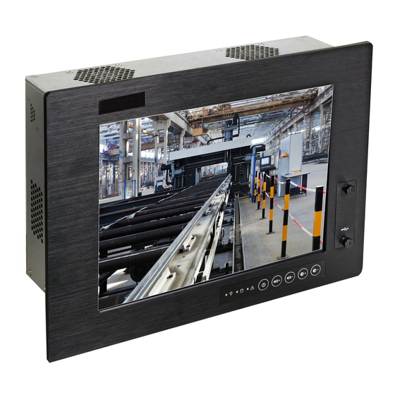
Chapter 1 Chapter 1 - Introduction Overview TPC121 TPC150 Chapter 1 Introduction www.dfi .com... -
Page 7: Key Features
Chapter 1 TPC170 Key Features TPC121/150/170 Processor 3rd/2nd Generation Intel ® Core processors Chipset Intel ® H61 Express Chipset 2 LAN ports 2 COM ports Dual Displays HDMI and DVI-I 4 Type A USB 2.0/1.1 ports at the bottom 2 Type A USB 2.0/1.1 ports at the front panel... -
Page 8: Specifications
Chapter 1 Specifications TPC121 Processor System • Processors: I/O Ports • Front - 3rd generation Intel Core processors - 2 Type A USB 2.0/1.1 ports ® - 2nd generation Intel Core processors ® - 5 function keys - Supports up to 77W TDP - 3 LED indicators: Power, HDD, Alarm •... - Page 9 Chapter 1 Specifications TPC150 Processor System • Processors: I/O Ports • Front - 3rd generation Intel ® Core processors - 2 Type A USB 2.0/1.1 ports - 2nd generation Intel ® Core processors - 5 function keys - Supports up to 77W TDP - 3 LED indicators: Power, HDD, Alarm •...
- Page 10 Chapter 1 Specifications TPC170 Processor System • Processors: I/O Ports • Front - 3rd generation Intel ® Core processors - 2 Type A USB 2.0/1.1 ports - 2nd generation Intel Core processors - 5 function keys ® - Supports up to 77W TDP - 3 LED indicators: Power, HDD, Alarm •...
-
Page 11: Getting The Know The Tpc121/150/170
Chapter 1 Getting to Know the TPC121/150/170 Front View Bottom View COM 2 Power Switch Line-in DVI-I +16-30V DC-in PS/2 Mouse Line-out +19V DC-in USB 2.0 COM 1 PS/2 KB HDMI Mic-in HDMI Port Use to connect an HDMI device. -
Page 12: Mechanical Dimensions
Chapter 1 Mechanical Dimensions TPC121 TPC150 Top View Top View 106.00 103.00 410.00 345.00 37.00 34.00 6.00 306.00 248.50 6.00 Left View Front View Right View Left View Front View Right View Bottom View Bottom View 330.00 110.00 90.00 270.00 100.00... - Page 13 Chapter 1 TPC170 Motherboard Dimensions Top View 10.16 106.00 443.78 37.00 0.00 339.50 6.00 21.09 22.86 46.94 49.47 49.47 64.59 78.53 97.23 Left View Front View Right View 124.47 124.47 141.39 Bottom View 153.34 154.94 159.84 364.00 154.94 144.00 100.00 75.00 Rear View 144.00...
-
Page 14: Chapter 2 - Getting Started
• CD-ROM drive (for installing software/drivers) • Screwdriver • Memory module (optional) Installing Devices The following are devices that can be installed in the TPC121/150/170 system. • Memory module • SATA hard drive • Mini PCIe card Configuring the BIOS To get you started, you may need to change configurations such as the date, time and the type of hard disk drive. -
Page 15: Chapter 3 - Installing Devices
5. The memory socket, expansion slots, Mini PCIe slot and SATA drive bay are readily acces- sible after removing the chassis cover. Removing the Chassis Cover TPC121 1. Make sure the system and all other peripheral devices connected to it has been powered- off. -
Page 16: Installing An Sodimm
Chapter 3 Installing an SODIMM 4. Grasping the module by its edges, position the module above the socket with the notch in the socket aligned with the key on the module. Apply fi rm even pressure to each end of the module until it slips down into the socket. -
Page 17: Installing A Sata Drive
Chapter 3 Installing a SATA Drive 2. Remove the mounting screws that secure the HDD bracket to the drive bay. TPC121 1. Locate the SATA drive bay in the chassis. TPC121 Mounting Screw SATA drive bay TPC150/ TPC170 TPC150/ TPC170... - Page 18 Chapter 3 3. Align the mounting holes of the SATA drive with the mounting holes on the HDD bracket and then use the provided mounting screws to secure the drive in place. SATA drive Mounting hole HDD bracket Mounting screws Mountin Mounting screw Mounting screw...
-
Page 19: Installing A Mini Pcie Card
Chapter 3 Installing a Mini PCIe Card Latch 1. Locate the two Mini PCIe slots on the chassis. SATA data connector SATA power connector Mini PCIe slot Mini PCIe slot 2. The latch is used to lock the Mini PCIe card into position. Insert the latch into the mounting holes and then push the latch down until the clips at each end of the latch lock into position. -
Page 20: Removing The Latch
Chapter 3 3. The system board is equipped with a Mini PCIe slot. The Mini PCIe slot supports half length Mini PCIe card. Note the key on the slot. The key ensures the Mini PCIe card can be plugged into the slot in only one direction. -
Page 21: Installing The Mini Pcie Card
Chapter 3 Installing the Mini PCIe Card Installing the PCI and PCIe x1 Expansion Card 1. The PCI and PCIe x1 slots on the riser card are used to install the expansion cards. To install 1. Grasping the Mini PCIe card by its edges, align the card into the slot at an approximately 30 the expansion cards, you need to remove the mounting screws that secure the brackets to the degrees angle. -
Page 22: Connecting Cables To Terminal Blocks
Chapter 3 Connecting Cables to Terminal Blocks 2. Plug the terminal block into the DC-in connector and then tighten the screws to secure the terminal block in place. 1. Insert the cable end of the power adaptor to the terminal block. To fi rmly fi x the cable into the terminal block, use a screwdriver to clamp down the wires to the screw that is in the terminal block. -
Page 23: Chapter 4 - Jumper Settings
Chapter 4 Chapter 4 - Jumper Settings PS/2 Power Select Clear CMOS 1-2 On: +5V 2-3 On: (default) +5V_standby 1-2 On: Normal (default) 2-3 On: Clear CMOS Data JP2 is used to select the power of the PS/2 keyboard and PS/2 mouse ports. Selecting +5V_ standby will allow you to use the PS/2 keyboard or PS/2 mouse to wake up the system. -
Page 24: Usb Power Select
Chapter 4 USB Power Select Power-on Select USB 0-1/8-9 (JP4) 1-2 On: Power-on via power button 1-2 On: +5V 2-3 On: (default) (default) +5V_standby USB 2-3/10-11 (JP7) 2-3 On: Power-on via AC power; or Power-on via WOL after G3 1-2 On: +5V 2-3 On: (default) +5V_standby... -
Page 25: Com 1 Rs232/422/485 Select
Chapter 4 COM 1 Signal Select COM 1 RS232/RS422/RS485 Select JP1 (for COM 1) is used to configure the COM port to RS232, RS422 (Full Duplex) or RS485. The pin function of the COM ports will vary according to the jumper’s setting. 1-3 On: Pin-9 3-5 On: Pin-9 2-4 On: Pin-1... -
Page 26: Front Audio Or Audio Amplifier Select
Chapter 4 Front Audio or Audio Amplifier Select 1-3, 2-4 On: 3-5, 4-6 On: Front audio Audio Amplifier (default) JP5 is used to configure front audio or audio amplifier select. Chapter 4 Jumper Settings www.dfi .com... -
Page 27: Chapter 5 - Ports And Connectors
Chapter 5 Chapter 5 - Ports and Connectors USB Ports Front Panel I/O Port USB allows data exchange between your computer and a wide range of simultaneously acces- sible external Plug and Play peripherals. The system board is equipped with 2 USB 2.0/1.1 ports. •... -
Page 28: Bottom Panel I/O Ports
Chapter 5 Bottom Panel I/O Ports PS/2 Mouse and PS/2 Keyboard Ports COM 2 PS/2 Mouse Line-in DVI-I PS/2 K/B PS/2 Mouse Line-out USB 2.0 COM 1 PS/2 KB HDMI Mic-in The bottom panel I/O ports consist of the following: •... -
Page 29: Rj45 Lan Ports
Chapter 5 RJ45 LAN Ports USB Ports LAN 1 LAN 2 USB 1 USB 10-11 USB 0 USB 2-3 USB 2.0 N. C. +Data +Data -Data -Data USB 8 USB 9 USB 2.0 Features USB allows data exchange between your computer and a wide range of simultaneously acces- sible external Plug and Play peripherals. -
Page 30: Graphics Interface
Chapter 5 Graphics Interface Wake-On-USB Keyboard/Mouse The Wake-On-USB Keyboard/Mouse function allows you to use a USB keyboard or USB mouse The display ports consist of the following: to wake up a system from the S3 (STR - Suspend To RAM) state. To use this function: •... -
Page 31: Com (Serial) Ports
Chapter 5 COM (Serial) Ports Audio Line-in Line-out Mic-in COM 2: RS232 Rear audio COM 1: Front audio RS232/422/485 The pin function of COM 1 port will vary according to JP1’s setting. Refer to “COM1 RS232/ RS422/RS485 Select” in this chapter for more information. The serial ports are asynchronous communication ports with 16C550A-compatible UARTs that can be used with modems, serial printers, remote display terminals, and other serial devices. -
Page 32: I/O Connectors
Chapter 5 I/O Connectors BIOS Setting Configure the onboard audio in the Chipset menu (“South Bridge” submenu) of the BIOS. SATA (Serial ATA) Connectors Refer to chapter 3 for more information. Driver Installation Install the audio driver. Refer to chapter 8 for more information. SATA 2.0 3Gb/s Features •... -
Page 33: Digital I/O Connector And Digital I/O Power Connector
Chapter 5 Digital I/O Connector Audio Amplifier Connector Digital I/O Power Connector Digital I/O power Out L- Digital I/O Out R+ Audio Amplifier Out R- Out L+ The audio amplifier connector which has amplifying feature is used to connect external speak- ers. -
Page 34: Chassis Intrusion Connector
Chapter 5 Chassis Intrusion Connector Cooling Fan Connectors Ground System_fan 2 Power Sense Signal Ground System_fan 1 Ground Power Sense Speed Control Sense Power CPU fan Ground The board supports the chassis intrusion detection function. Connect the chassis intrusion The fan connectors are used to connect cooling fans. The cooling fans will provide adequate sensor cable from the chassis to this connector. -
Page 35: Standby Power Led
Chapter 5 Standby Power LED Power Connectors 10 20 Standby Power LED +12V ATX power 5VSB PW-OK Ground PS-ON Ground 3.3V -12V 3.3V 3.3V +12V +12V ATX 12V Use a power supply that complies with the ATX12V Power Supply Design Guide Version 1.1. This LED will lit red when the system is in the standby mode. -
Page 36: Expansion Slots
Chapter 5 Expansion Slots Front Panel Connectors Mini PCI Express PWR-LED HDD-LED RESET-SW PWR-BTN PCI Express x16 PCI Express x16 Slot HDD-LED - HDD LED The PCI Express x16 slot is an interface for the X100-3PE2 riser card. The X100-3PE2 fea- This LED will light when the hard drive is being accessed. -
Page 37: Battery
Chapter 5 Battery SDVO Connector Battery SDVO The SDVO connector is used to connect the optional SDVO-LVDS daughterboard. The lithium ion battery powers the real-time clock and CMOS memory. It is an auxiliary source Pins Pin Assignment Pins Pin Assignment of power when the main power is shut off. -
Page 38: Sdvo-Lvds Daughterboard (Optional)
Chapter 5 SDVO-LVDS Daughterboard (optional) Power Select for the LCD Panel Features • Chrontel CH7308B • Supports 18/24-bit 1600x1200 LVDS panel (default 1280x1024) 1-2 On: +12V • 1 LVDS LCD panel connector • 1 LCD/Inverter power connector • SDVO interface •... - Page 39 Chapter 5 LVDS LCD Panel and LCD Inverter Power Connectors LVDS LCD Panel Connector Pins Function Pins Function LVDS_Out3+ LVDS_Out7+ LVDS_Out3- LVDS_Out7- LCD/Inverter power LVDS_Out2+ LVDS_Out6+ LVDS_Out2- LVDS_Out6- LVDS_Out1+ LVDS_Out5+ LVDS LCD panel LVDS_Out1- LVDS_Out5- The system board allows you to connect a LCD Display Panel by means of the LVDS LCD panel connector and the LCD/Inverter power connector.
-
Page 40: Installing The Sdvo-Lvds Daughterboard Onto The Motherboard (Optional)
Chapter 5 LCD/Inverter Power Connector Installing the SDVO-LVDS Daughterboard onto the Motherboard (optional) Pins Function Important: The motherboard used in this section is for reference purpose only and may not resemble your motherboard. These illustrations are mainly to guide you on how to install SDVO-LVDS onto the motherboard of your choice. - Page 41 Chapter 5 3. While supporting the mounting screw at the bottom, from the top side of the board, fasten a bolt into the screw. SDVO connector on the motherboard 5. Press the daughterboard down firmly until it is completely seated on the SDVO connector Bolt of the motherboard.
-
Page 42: Chapter 6 - Mounting Options
Chapter 6 Chapter 6 - Mounting Options 3. Attach the other bracket (wall mount bracket 2) to the rear of the Panel PC. Wall Mount The wall mount kit includes the following: • 2 Wall mount brackets • Bracket screws Mounting screw Wall mount bracket 2 Hooks... -
Page 43: Panel Mount
Chapter 6 Panel Mount The panel mounting kit includes the following: • 10 mounting clamps (TPC121 and TPC150) • 12 mounting clamps (TPC170) 1. Select a place on the panel where you will mount the Panel PC. 2. Cut out a shape on the panel that corresponds to the Panel PC’s rear dimensions. - Page 44 Chapter 6 4. Slide the Panel PC through the hole until it is properly fi tted against the panel. 5. Position the mounting clamps along the rear edges of the Panel PC, fi tting them into the slits that are around the Panel PC. 296.00 Slit for mounting the clamp Mounting clamp...
-
Page 45: Chapter 7 - Bios Setup
“Press DEL to run setup” will appear on the screen. If the message disappears before you respond, restart the system or press the “Reset” button. You may also restart the system by pressing the <Ctrl> <Alt> and <Del> keys simultaneously. Chapter 7 BIOS Setup www.dfi.com... -
Page 46: Ami Bios Setup Utility
The time format is <hour>, <minute>, <second>. The time is based on the 24-hour military-time clock. For example, 1 p.m. is 13:00:00. Hour displays hours from 00 to 23. Minute displays minutes from 00 to 59. Second displays seconds from 00 to 59. Chapter 7 BIOS Setup www.dfi.com... - Page 47 When Enabled, the system uses the RTC to generate a wakeup event. When this feature is set to Automatic, the CPU’s fan speed will rotate according to the CPU’s temperature. The higher the temperature, the faster the speed of rotation. Chapter 7 BIOS Setup www.dfi.com...
- Page 48 When disabled, only one thread per enabled core is enabled. Active Processor Cores Number of cores to enable in each processor package. Intel Virtualization Technology When this field is set to Enabled, the VMM can utilize the additional hardware capabilities provided by Vanderpool Technology. Chapter 7 BIOS Setup www.dfi.com...
- Page 49 This option configures the Serial ATA drives as Parallel ATA storage devices. Disabled Keeps USB devices available only for EFI applications. EHCI Hand-off This is a workaround for OSes that does not support EHCI hand-off. The EHCI ownership change should be claimed by the EHCI driver. Chapter 7 BIOS Setup www.dfi.com...
- Page 50 Version 2.14.1219. Copyright (C) 2011 American Megatrends, Inc. Watchdog Timer Serial Port Enable or disable Super I/O watchdog timer. Enables or disables the serial port. Change Settings Selects the IO/IRQ setting of the I/O device. Chapter 7 BIOS Setup www.dfi.com...
- Page 51 Ipv4 PXE Support Enable Ipv4 PXE Boot Support. If disabled Ipv4 PXE boot option will not be created. Ipv6 PXE Support Enable Ipv6 PXE Boot Support. If disabled Ipv6 PXE boot option will not be created. Chapter 7 BIOS Setup www.dfi.com...
- Page 52 ME is on at Sx state.) High Precision Timer Enable or disable the High Precision Timer. After G3 Power Off / WOL Power-on the system via WOL after G3. Power On Power-on the system after G3. Chapter 7 BIOS Setup www.dfi.com...
- Page 53 Version 2.14.1219. Copyright (C) 2011 American Megatrends, Inc. Version 2.14.1219. Copyright (C) 2011 American Megatrends, Inc. EHCI1 and EHCI2 These fields are used to enable or disable USB 2.0. USB Ports Per-Port Disable Controller Control each of the USB ports (0~13) disabling. Chapter 7 BIOS Setup www.dfi.com...
- Page 54 PEG-Gen X [Gen1] [Enabled] Enable PEG → ←: Select Screen ↑↓: Select Item Enter: Select +/ -: Change Opt. General Help Previous Values Optimized Defaults ESC: Exit Version 2.14.1219. Copyright (C) 2011 American Megatrends, Inc. Chapter 7 BIOS Setup www.dfi.com...
- Page 55 Enables or disables the quiet boot function. → ←: Select Screen ↑↓: Select Item Enter: Select +/ -: Change Opt. General Help Previous Values Optimized Defaults ESC: Exit Version 2.14.1219. Copyright (C) 2011 American Megatrends, Inc. Chapter 7 BIOS Setup www.dfi.com...
- Page 56 Sets the user password. Launch Storage OpROM policy Controls the execution of UEFI and legacy storage OpROM. Other PCI device ROM priority For PCI devices other than Network, Mass Storage, or Video defines which OpROM to launch. Chapter 7 BIOS Setup www.dfi.com...
-
Page 57: Updating The Bios
A dialog box will appear. Select Yes to restore the default values of all the setup options. Launch EFI Shell from filesystem device Attempts to Launch EFI Shell application (Shellx64.efi) from one of the available filesystem devices. Chapter 7 BIOS Setup www.dfi.com... -
Page 58: Chapter 8 - Supported Software
Insert the CD into a CD-ROM drive. The autorun screen (Mainboard Utility CD) will appear. If after inserting the CD, “Autorun” did not automatically start (which is, the Mainboard Utility CD screen did not appear), please go directly to the root directory of the CD and double-click “Setup”. Chapter 8 Supported Software www.dfi.com... - Page 59 To install the driver, click “Microsoft .NET Framework 3.5” on the main menu. 1. Read the license agreement carefully. Click “I have read and accept the terms of the License Agreement” then click Install. 2. Setup is now installing the driver. Chapter 8 Supported Software www.dfi.com...
-
Page 60: Intel Chipset Software Installation Utility
To install the utility, click “Intel Chipset Software Installation Utility” on the main menu. 1. Setup is ready to install the utility. Click Next. 4. Click Finish to exit setup. 2. Read the license agreement then click Yes. Chapter 8 Supported Software www.dfi.com... - Page 61 (while WinSAT is running) before the Windows Vista desktop appears. The “blank screen” period is the time Windows is testing the graphics perfor- mance. 2. Read the license agreement then click Yes. 3. Click Finish. Reboot the system for DirectX to take effect. Chapter 8 Supported Software www.dfi.com...
- Page 62 Restarting the system will allow the new software installation to take effect. 5. Click “Yes, I want to restart this computer now” then click Finish. Restarting the system will allow the new software installation to take effect. Chapter 8 Supported Software www.dfi.com...
- Page 63 1. Setup is ready to install the driver. Click Next. 5. After completing installa- tion, click Finish. 2. Click “I accept the terms in the license agreement” then click “Next”. 3. Select the program featuers you want installed then click Next. Chapter 8 Supported Software www.dfi.com...
- Page 64 To install the driver, click “Intel Management Engine Drivers” on the main menu. 1. Setup is ready to install the driver. Click Next. 4. After completing installa- tion, click Finish. 2. Read the license agreement then click Yes. Chapter 8 Supported Software www.dfi.com...
- Page 65 7. Setup is currently installing the utility. Important: Perform steps 1-3 only when using Windows 7 or Windows Vista. 5. Setup is ready to install the utility. Click Next. 8. After completing instal- lation, click Finish to exit setup. Chapter 8 Supported Software www.dfi.com...
- Page 66 Chapter 8 DFI Utility 3. Enter “User name” (SB102) and “Organization” information DFI Utility provides information about the board, Watchdog, DIO, and Backlight. then click “Next”. To access the utility, click “DFI Utility” on the main menu. Note: If you are using Windows 7, you need to access the operating system as an administrator to be able to install the utility.
- Page 67 To install the reader, click “Adobe Acrobat Reader 9.3” on the main menu. 1. Click Next to install or click Change Destination Folder to select another folder. 2. Click Install to begin installa- tion. 3. Click Finish to exit installation. Chapter 8 Supported Software www.dfi.com...
-
Page 68: Appendix A - Watchdog Sample Code
;Select watchdog timer register DX,AL DX,2FH AL,10H ;Set watchdog timer value DX,AL DX,2EH AL, F5H ;Select watchdog Control Register DX,AL DX,2FH AL,61H ;Set Watchdog Control Value DX,AL ;---------------------------------------------------------------- ;(1) Exit extended function mode ;---------------------------------------------------------------- DX,2EH AL,AAH DX,AL Appendix A Watchdog Sample Code www.dfi.com... -
Page 69: Appendix B - System Error Message
The BIOS reports memory test fail if the memory has error(s). VIDEO selection. FLOPPY DISK(S) fail (80) Unable to reset floppy subsystem. FLOPPY DISK(S) fail (40) Floppy type mismatch. Hard Disk(s) fail (80) HDD reset failed. Hard Disk(s) fail (40) HDD controller diagnostics failed. Appendix B System Error Message www.dfi.com... -
Page 70: Appendix C - Troubleshooting Checklist
4. There is not enough space left on the diskette. Use another diskette with adequate storage 4. Adjust the brightness of the display by turning the monitor’s brightness control knob. space. Appendix C Troubleshooting Checklist www.dfi.com... -
Page 71: Hard Drive
Nothing happens when a key on the keyboard was pressed. 1. Make sure the keyboard is properly connected. 2. Make sure there are no objects resting on the keyboard and that no keys are pressed dur- ing the booting process. Appendix C Troubleshooting Checklist www.dfi.com...
Need help?
Do you have a question about the TPC121 and is the answer not in the manual?
Questions and answers