
Related Manuals for DFI KS200


Summary of Contents for DFI KS200
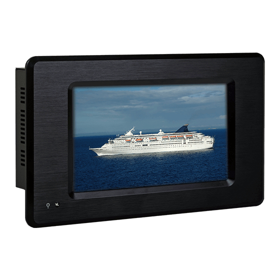
- Page 1 KS200/202 Touch Panel PC User’s Manual A23230340 Chapter 1 Introduction www.dfi .com...
-
Page 2: Copyright
Copyright FCC and DOC Statement on Class B This publication contains information that is protected by copyright. No part of it may be re- This equipment has been tested and found to comply with the limits for a Class B digital produced in any form or by any means or used to make any transformation/adaptation without device, pursuant to Part 15 of the FCC rules. -
Page 3: Table Of Contents
Chapter 1 - Introduction ................6 Overview ....................... 6 Key Features ....................7 Specifications ....................8 Getting the Know the KS200/202 ............10 Mechanical Dimensions ................11 Chapter 2 - Installation ..............12 Connecting Cables to Terminal Blocks ..........12 Chapter 3 - Ports and Connectors .......... -
Page 4: About This Manual
About this Manual Static Electricity Precautions An electronic file of this manual is included in the CD. To view the user’s manual in the CD, in- It is quite easy to inadvertently damage your PC, system board, components or devices even sert the CD into a CD-ROM drive. -
Page 5: Safety Precautions
Safety Precautions About the Package • Use the correct DC input voltage range. The package contains the following items. If any of these items are missing or damaged, please contact your dealer or sales representative for assistance. • Unplug the power cord before removing the system chassis cover for installation or servic- ing. -
Page 6: Chapter 1 - Introduction
Chapter 1 Chapter 1 - Introduction Overview KS200 KS202 Chapter 1 Introduction www.dfi .com... -
Page 7: Key Features
Key Features • TI ® AM3517 Sitara ARM Cortex-A8 • 7" WVGA Touch Screen Fanless Panel PC • 512MB DDR2 onboard • 512MB NAND Flash onboard KS200 KS202 Open Frame SD/MMC 1 SD/MMC card socket 1 LAN port 2 COM ports 2 Type A USB 2.0/1.1 ports... -
Page 8: Specifications
Chapter 1 Specifications KS200 Processor System I/O Ports Front • • TI AM3517 Sitara ARM Cortex-A8 ® - 1 Power LED • Top Memory • 512MB DDR2 onboard - 1 SD/MMC card socket - 4 DDR2 64Mx16 RAM • Bottom •... - Page 9 Chapter 1 Specifications KS202 Processor System I/O Ports • Front • TI ® AM3517 Sitara ARM Cortex-A8 - 1 Power LED • Top Memory • 512MB DDR2 onboard - 1 SD/MMC card socket - 4 DDR2 64Mx16 RAM • Bottom LCD and •...
-
Page 10: Getting The Know The Ks200/202
Chapter 1 Getting to Know the KS200/202 Front View Bottom View RS232 COM 14-30V DC-in Line-Out Power Switch 12-bit GPIO RS232/422/485 COM COM Ports Power LED Used to connect serial devices. USB Ports Used to connect USB 2.0/1.1 devices. Power LED Indicates the power status of the system. -
Page 11: Mechanical Dimensions
Chapter 1 Mechanical Dimensions KS200 KS202 214.60 214.60 Top View 230.40 Top View 221.00 190.00 154.40 (V,A FOR T/P) 35.80 20.20 Ø3.50 153.00 (A,A FOR T/P) 95.00 11.20 Left View Right View 90.00 190.00 20.20 Front View Left View Right View 235.00... -
Page 12: Chapter 2 - Installation
Chapter 2 Chapter 2 - Installation 2. Plug the terminal block into the DC-in connector and then tighten the screws to secure the terminal block in place. Connecting Cables to Terminal Blocks Important: DC-in When installing the touch panel PC, make sure the power is off. Failure to turn off, may cause connector severe damage to the system. -
Page 13: Chapter 3 - Ports And Connectors
Chapter 3 Chapter 3 - Ports and Connectors SD/MMC Top Panel I/O Port SD/MMC The front panel I/O port consist of the following: SD/MMC • 1 SD/MMC slot This expansion port is used to insert a Secure Digital (SD) or Multimedia Card (MMC) device. Aside from storing data files, an SD card is also capable of storing powerful software applica- tions. -
Page 14: Bottom Panel I/O Ports
Chapter 3 GPIO Bottom Panel I/O Ports RS232 COM 14-30V DC-in Line-Out Power Switch 12-bit GPIO RS232/422/485 COM The bottom panel I/O ports consist of the following: • 1 12-bit GPIO • 1 Line-Out jack • 1 RS232 COM port The Digital I/O connector provides powering-on function to an external device that is con- •... - Page 15 Chapter 3 Line-out RS232 COM 1 COM 1: RS232 This jack is used to connect a headphone or external speakers. COM 1 is fixed at RS232. 1 2 3 4 5 Chapter 3 Ports and Connectors www.dfi .com...
- Page 16 Chapter 3 RS232/422/485 COM 2 LAN Port COM 2: RS232/422/485 The LAN port allows the system board to connect to a local area network by means of a net- COM 2 work hub. 1 2 3 4 5 1 2 3 4 5 1 2 3 4 5 Chapter 3 Ports and Connectors www.dfi...
- Page 17 Chapter 3 USB Ports USB 1-2 USB allows data exchange between your computer and a wide range of simultaneously acces- sible external Plug and Play peripherals. The system board is equipped with two onboard USB 2.0/1.1 ports (USB 1-2). Chapter 3 Ports and Connectors www.dfi...
-
Page 18: Chapter 4 - Mounting Options
Chapter 4 Chapter 4 - Mounting Options 3. Attach the other bracket (wall mount bracket 2) to the rear of the Panel PC. Wall Mount The wall mount kit includes the following: Mounting screw • 2 Wall mount brackets Wall mount bracket 2 •... -
Page 19: Panel Mount
Chapter 4 Panel Mount The panel mounting kit includes the following: • 6 mounting clamps Select a place on the panel where you will mount the Panel PC. Cut out a shape on the panel that corresponds to the Panel PC’s rear dimensions (217.6mm x 128.6mm). - Page 20 Chapter 4 4. Slide the Panel PC through the hole until it is properly fi tted against the panel. 5. Position the mounting clamps along the rear edges of the Panel PC, fi tting them into the slits that are around the Panel PC. Mounting 128.60 clamp...
- Page 21 MLO file from the XLDRSD.nb0. This file is the SD boot version of xldr. EBOOTSD.nb0 The build process also creates the EBOOTSD.NB0 file. This file is the exact representation of EBOOT as it must appear in memory. This file is used with MLO when booting from SD Card. Appendix A Software Support www.dfi.com...
- Page 22 • 1 stop bit TI SDCard Utility • No parity Manual Note: User Guide DFI RS232 standard cable (NO.332-7530404-000) or the following same specifications cable. RS232 Cable Pin Assignments DB9 Connector (RS232) PC Side DB9 Connector (RS232) Product Side Femal...
- Page 23 SD or NAND version of EBOOT. Select Debug Device This menu option configures the KITL transport that will be used in a KITL enabled OS image. The options include Ethernet (default) or USB RNDIS. Appendix A Software Support www.dfi.com...
- Page 24 5. Exit the menus to boot the CE image from the SD card using option 0. 7. Use the following switch setting on the TS200 to boot from NAND. 6. Please wait a moment while the image is read and booted. SW3 Switch Position Appendix A Software Support www.dfi.com...
- Page 25 Appendix A How to update WinCE Image Demo Application Program DFI provides some Application Programs in TS200, including the following items: Load OS image through SD card. Please follow the flow below: − GPIO 1. Please prepare a SD card (the capacity must be more than 64MB), and insert your card into the computer.
- Page 26 Set Mode – Set UART mode (COM2 only) Stop WDT – Disable WDT count. • RS232 (default) Current Time – When the WDT is started. Display the counting time of seconds. • RS485 • RS422 Appendix A Software Support www.dfi.com...
Need help?
Do you have a question about the KS200 and is the answer not in the manual?
Questions and answers