Advertisement
Quick Links
Quick Installation Guide
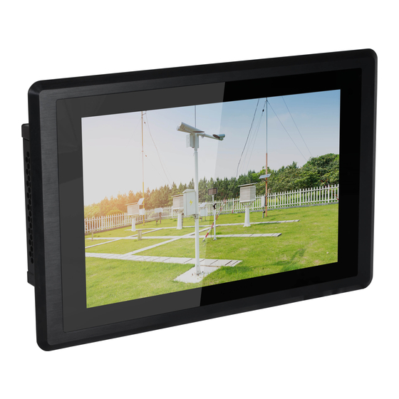
KS101-BT
Package Contents
• KS101-BT Touch Panel PC
• One sheet of poron foam
• One HDD drive bay kit
Top View
Bottom View
DFI reserves the right to change the specifications at any time prior to the product's release. This QIG may
be based on editions that do not resemble your actual products. For the latest revision and more details of
the installation procedure, please refer to go.dfi.com/KS101-BT or scan the QR code on the right.
COM 4/ 8-bit DIO
Antenna
hole
LAN 2
LAN 1
Line-out
USB 2.0
DC-in
COM 2
(RS232/RS422/RS485)
USB 3.0
COM 1
(RS232/RS422/RS485)
COM 5
(RS232)
Mic-in
COM 3
(RS232/RS422/RS485)
www.dfi.com
Antenna
hole
Power button
HDMI
Reset/
Status LED
1
Advertisement

Subscribe to Our Youtube Channel
Related Manuals for DFI KS101-BT


Summary of Contents for DFI KS101-BT
- Page 1 COM 3 (RS232/RS422/RS485) DFI reserves the right to change the specifications at any time prior to the product's release. This QIG may be based on editions that do not resemble your actual products. For the latest revision and more details of...
- Page 2 Removing the Chassis Cover Make sure the system and all other peripheral devices connected to it have been powered-off. Disconnect all power cords and cables. The 8 mounting screws on the rear side of the system are used to secure the cover to the chassis.
- Page 3 Installing a Mini PCIe Card The system board is equipped with 3 Mini PCIe slots: two full-size and one half-size slots. Here we will demonstrate the installation of a full-size Mini PCIe card (working in conjunction with a SIM card) for 4G connectivity.
- Page 4 Board Layout and Jumper Settings USB Power Select: 0 (JP5), 1-2 (JP6), 5-7 (JP7) Auto Power-on Select JP25 +5V_standby (default) 1-2 On Power-on via power button (default) 1-2 On 2-3 On Power-on via AC power 2-3 On Clear CMOS Data JP24 Normal (default) 1-2 On...
Need help?
Do you have a question about the KS101-BT and is the answer not in the manual?
Questions and answers