DFI KS070-AL Installation Manual
Hide thumbs
Also See for KS070-AL:
- Installation manual (12 pages) ,
- User manual (53 pages) ,
- Installation manual (12 pages)
Table of Contents
Advertisement
Quick Links
Download this manual
See also:
User Manual
KS070/150/190/215-AL Installation Guide
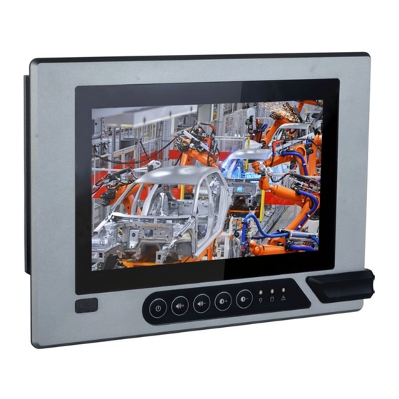
• One 7", 15", 19", or 21.5" Modular Touch Panel PC
• 3-pin and 2-pin Terminal Block Connectors
• SATA and Mini PCIe Installation Screws
• 1 DVD disk includes:
- Manual
DFI reserves the right to change the specifications at any time prior to the
product's release. For the latest revision and more details of the installation
procedure, please refer to the user's manual on the website.
Package Contents
www.dfi.com
1
Advertisement
Table of Contents

Related Manuals for DFI KS070-AL


Summary of Contents for DFI KS070-AL
-
Page 1: Package Contents
• 1 DVD disk includes: - Manual DFI reserves the right to change the specifications at any time prior to the product's release. For the latest revision and more details of the installation procedure, please refer to the user's manual on the website. -
Page 2: Bottom View
Panel COM 1 (RS232/RS422/RS485) LAN 1 LAN 2 COM 2 (RS232/RS422/RS485) Top View Power Button Antenna Hole Power Management Switch Line-out HDD LED Mic-in USB 3.0 USB 2.0 Power Connector Status LED Bottom View Reset Switch Distant Switch Grounding DP++ SATA Drive Bay Notes on Power Management Settings: AT Mode: The system powers on when power is applied. -
Page 3: Installing A Sim Card
Installing a SIM Card The SIM card socket can be accessed without opening the chassis. It is lo- cated on the side of the box module. 1. Remove the screw to open the slot. Side View SIM Card Slot Screw 2. -
Page 4: Installing A Sata Drive
Installing a SATA Drive The SATA drive tray can be easily accessed without opening the system. However, the system does not support hot-swapping hard drives; turn off the system first. 1. Locate the drive tray on the bottom panel and open it by releasing the thumbscrews. - Page 5 3. Slide the HDD into the drive bay by aligning the HDD's data and power connectors with the system's SATA data and power connectors. Then close the drive tray and secure the drive in place with the thumbscrews.
-
Page 6: Removing The Chassis Cover
Removing the Chassis Cover Installing internal components requires you to remove the chassis. Please use the following procedure to open the chassis cover. 1. Make sure the system and all other peripheral devices connected to it have been powered-off. 2. Disconnect all power cords and cables. 3. - Page 7 Installing a Mini PCIe Card/mini-mSATA The system board is equipped with 2 Mini PCIe slots: one full-size (black) and one half-size (white) slots. Here we will demonstrate the installation of a full-size Mini PCIe card (working in conjunction with a SIM card) for 3G/4G connectivity.
-
Page 8: Installing A Sodimm
Installing a SODIMM The system supports one DDR3L SODIMM socket. To install a memory module, grasp the memory module by its edges and align the module’s notch with the socket’s notch; then insert the memory into the socket at an angle and push it down until you feel a click. Insert the Memory at an Angle SODIMM Module... - Page 9 Assembling the Modular Panel PC The modular panel PC comprises two parts: a box module and a panel mod- ule. The assembly of these two parts is easy thanks to DFI's ADP (Adaptive Display Platform) innovation, which makes the box modules and the pane modules interchangeable.
- Page 10 3. Make sure that the box module seats on top of the panel module with the alignment post effortlessly sliping into the designated holes on the box module. Press to install these two modules and secure the installation with 4 mouting screws. Mounting Screw...
-
Page 11: Mounting Options
Mounting Options Wall mount The VESA-mount specifications for this device is 75 x 75 (mm). Please use a compatible VESA mount kit that can sustain the weight and size of this device. Wall Mount Bracket 1 Wall Mount Bracket 2 1. - Page 12 4. Attach the other bracket (wall mount bracket 2) to the rear of the Panel PC. Thumb Screw Hooks Wall mount Bracket 2 Mounting Screw 5. Slide the Panel PC to "wall mount bracket 1" to attach the two brackets with the hooks.
-
Page 13: Panel Mount
Panel mount The panel mounting kit includes the following: • 10 mounting clamps 1. Before starting any installation procedures, attach the poron foam to the Panel PC. 2. Select a place on the panel (or wall) where you will mount the Panel PC. 3. - Page 14 Mounting Clamp Slit for Mounting the Clamp 6. The first and second clamps must be positioned and secured diagonally prior to mounting the rest of the clamps. Tighten the clamp’s screw using an electric screwdriver by pressing the white plastic cap onto the back of the panel.
-
Page 15: Board Layout And Jumper Settings
Board Layout and Jumper Settings COM 2 COM 1 Battery COM 4 COM 3 USB2_6/7 SMBus Digital I/O CMOS (J6) (J7) (SW2) Digital I/O Power (J9) Intel Atom Distant DC-in Switch (3-pin terminal) Power Connector (J11) 1 2 3 DC-in USB 3_1/2 USB 2_3/4 power mode... - Page 16 Ignition Power-on/off Delay Settings The system comes with in-vehicle power management. The BIOS setup utility can be used to turn on or off the system with a specific on/off delay time. Use the following procedure to enable this function. 1. Press “Delete” to enter the BIOS menu when the system powers on. 2.
- Page 17 Power on/Power off Delay Time: Specify the number of seconds after which the system will start the power-on or power-off process. Notes: Please save your changes of the BIOS settings: Exit-> Exit Saving Changes. The "Status LED" on the bottom panel will start blinking once the above settings take effect.
- Page 18 Flowcharts for Ignition Power Control These flowcharts illustrate the startup and shutdown processes that the system goes through using ignition power control. System startup with power management setting set to IGN mode (please refer to page 2) Counts down System off System boots System on ACC on...
Need help?
Do you have a question about the KS070-AL and is the answer not in the manual?
Questions and answers