Advertisement
Quick Links
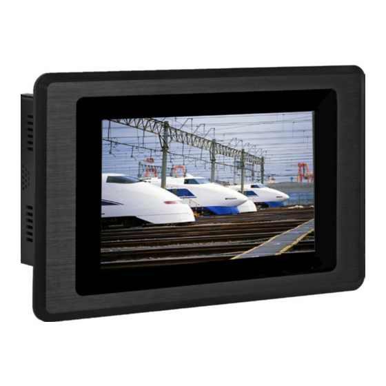
KS070-FS Installation Guide
Top Panel I/O Ports
SD
COM
Bottom Panel I/O Ports
USB 2.0
DC-in
Line-out/Mic-in
HDMI
LAN
Power Switch
COM
Mini USB
8-bit DIO
(RS232/422/485)
DFI reserves the right to change the specifications at any time prior
to the product's release. This QIG is based on versions that may not
resemble your actual products. For the latest revision and details of the
installation process, please refer to related technical docs on our website
at http://go.dfi.com/KS070-FS.
1
Advertisement

Subscribe to Our Youtube Channel
Related Manuals for DFI KS070-FS


Summary of Contents for DFI KS070-FS
- Page 1 8-bit DIO (RS232/422/485) DFI reserves the right to change the specifications at any time prior to the product's release. This QIG is based on versions that may not resemble your actual products. For the latest revision and details of the installation process, please refer to related technical docs on our website at http://go.dfi.com/KS070-FS.
- Page 2 Connecting the Cable to the Terminal Block The system's power connector is a two-pole terminal block. Please insert the corresponding end ("+" or "-") of a power adaptor to the respective pole of the terminal block. Insert the cable end of the power adaptor to the terminal block. To firmly fix the cable into the terminal block, use a screwdriver to clamp down the wires to the screw that is in the terminal block.
- Page 3 Removing the Chassis Cover Before working inside the system, make sure the system has been powered off and disconnect all power cords and cables. The 8 mounting screws on the sides and bottom of the system are used to secure the cover to the chassis.
- Page 4 Board Layout and Jumper Settings DC-in 12-36V HDMI Mic-in/ Line-out USB 2.0 Mic-in/Line-out AMP_L Battery Select (JP8) Mic-in/Line-out Select (JP7) AMP_R COM RS232/UART5 Select Download Mode (JP11)/(JP12) Select (JP9) Digital I/O IT8518E CAN-bus (optional) Panel Power Select (JP2) COM 1 RS232/422/485 Touch Panel Power Select (JP3) Select (JP4)
Need help?
Do you have a question about the KS070-FS and is the answer not in the manual?
Questions and answers