Table of Contents
Advertisement
Quick Links
Download this manual
See also:
User Manual
TPC150-SD Installation Guide
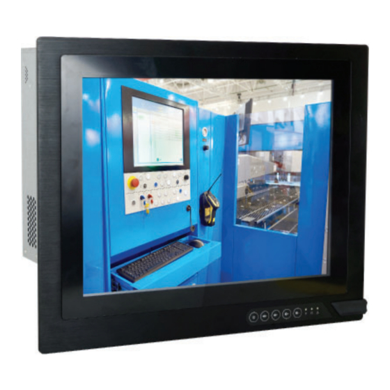
• One 15" Touch Panel PC
• One sheet of Poron foam
• 1 DVD disk includes:
- Manual
DFI reserves the right to change the specifi cations at any time prior to
the product's release. For the latest revision and more details of the
installation procedure, please refer to the user's manual on the website.
Package Contents
www.dfi .com
1
Advertisement
Table of Contents

Related Manuals for DFI TPC150-SD


Summary of Contents for DFI TPC150-SD
-
Page 1: Package Contents
• 1 DVD disk includes: - Manual DFI reserves the right to change the specifi cations at any time prior to the product's release. For the latest revision and more details of the installation procedure, please refer to the user's manual on the website. -
Page 2: Top Panel
Top Panel PS/2 Keyboard/Mouse Ports DVI-D Port Expansion Slots Power Switch COM Port (RS232) LAN1/LAN2 Top View DP++ Port USB 2.0 Ports USB 3.0 Ports VGA Port AC Power Socket... -
Page 3: Removing The Chassis Cover
Removing the Chassis Cover 1. Make sure the system and all other peripheral devices connected to it have been powered-off. 2. Disconnect all power cords and cables. 3. The 6 mounting screws on the bottom of the system are used to secure the cover to the chassis. -
Page 4: Installing A Sata Drive
Installing a SATA Drive The system can accomondate two SATA drives. Please use the following procedure to install SATA drives into the system. 1. Locate the SATA drive bay inside the system and remove the mounting screws that secure the HDD bracekt to the drive bay. SATA drive bay HDD bracket Bracket screw... - Page 5 3. Place the SATA drive (with the HDD bracket) back into the system. Align the mounting holes on the HDD bracket with the mounting holes on the SATA drive bay and then use the provided mounting screws to secure the drive in place. Mounting screw Mounting screw 4.
-
Page 6: Installing A Mini Pcie Card
Installing a Mini PCIe Card The system board is equipped with one Mini PCIe slot that supports mSATA and PCIe interfaces. Use the following procedure to install a Mini PCIe card: Align the notch in the connector of the PCIe card with the key in the connector on the system board and use the provided mounting screws to secure the card on the system board. -
Page 7: Installing A Pcie Expansion Card
Use the following procedure to install a Mini PCIe card: Note: The system provides two optioanl riser cards to accommodate different types of PCIe expansion slots: (DFI model: T100-2E) The riser card provides 2 x PCIe Gen3 x8 expansion slots... - Page 8 3. Install the bracket to secure the PCIe card in place. Front View...
-
Page 9: Mounting Options
Mounting Options VESA mount The VESA mount kit includes the following: • 2 VESA mount brackets • Bracket screws VESA mount bracket 1 VESA mount bracket 2 1. Select a place on the wall where you will mount the Panel PC. 2. - Page 10 3. Attach the other bracket (VESA mount bracket 2) to the rear of the Panel PC. Mounting screw VESA mount bracket 2 Mounting screw Hooks 4. Slide the Panel PC to "VESA mount bracket 1" to attach the two brackets with the hooks.
-
Page 11: Panel Mount
Panel mount The panel mounting kit includes the following: • 6 mounting clamps 1. Select a place on the panel (or wall) where you will mount the Panel PC. 2. Cut out a shape on the panel that corresponds to the Panel PC’s rear dimensions (383mm x 310mm) and ensure that the Panel PC can be fi... - Page 12 5. The fi rst and second clamps must be positioned and secured diagonally prior to mounting the rest of the clamps. Tighten the clamp’s screw using an electric screwdriver by pressing the white plastic cap onto the back of the panel. The illustration below shows that all clamps are properly mounted.
-
Page 13: Board Layout And Jumper Settings
Board Layout and Jumper Settings Mini PCIe Signal Select (JP1) LCD/Inverter Power Select (JP2) USB 2.0 Panel Power Select (JP7) (JP6) USB 11-12 COM1 RS232/Power Select USB 7-8 COM2 RS232/Power Select (JP8) SATA 0 SATA 2 SATA 3 PS/2 LVDS LCD Panel USB 5-6 (JP7) SATA 3.0...
Need help?
Do you have a question about the TPC150-SD and is the answer not in the manual?
Questions and answers