DFI TPC121 Installation Manual
Hide thumbs
Also See for TPC121:
- Quick manual (4 pages) ,
- User manual (71 pages) ,
- User manual (82 pages)
Advertisement
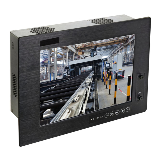
TPC121/150/170/190-SB
Installation Guide
Package Contents
• 1 TPC121/150/170/190 Panel PC
• 1 120W power adapter
(only for models below:
TPC-1212TR-SBDCR-R10
TPC-1502TR-SBDCMR-R10
TPC-1502TR-SBDCMR-R11
TPC-1702TR-SBDCMR-R10
TPC-1702TR-SBDCMR-R11
TPC-1902TR-SBDCMR-R10
TPC-1902TR-SBDCMR-R11)
• 1 Quick Installation Guide
• 1 CD disk includes:
- Drivers/Manual
Optional Items
• Wall Mount
• Panel Mount
• Power Cord
www.dfi .com
1
Advertisement
Table of Contents

Subscribe to Our Youtube Channel
Related Manuals for DFI TPC121


Summary of Contents for DFI TPC121
-
Page 1: Installation Guide
TPC121/150/170/190-SB Installation Guide Package Contents • 1 TPC121/150/170/190 Panel PC • 1 120W power adapter (only for models below: TPC-1212TR-SBDCR-R10 TPC-1502TR-SBDCMR-R10 TPC-1502TR-SBDCMR-R11 TPC-1702TR-SBDCMR-R10 TPC-1702TR-SBDCMR-R11 TPC-1902TR-SBDCMR-R10 TPC-1902TR-SBDCMR-R11) • 1 Quick Installation Guide • 1 CD disk includes: - Drivers/Manual Optional Items •... - Page 2 Installing a SATA Drive 1. Locate the SATA drive bay in the chassis. TPC121/TPC190-SB SATA drive bay TPC150/ TPC170 SATA drive bay...
- Page 3 2. Remove the mounting screws that secure the HDD bracket to the drive bay. TPC121/TPC190-SB Mounting Screw TPC150/ TPC170 Mounting Screw...
- Page 4 3. Align the mounting holes of the SATA drive with the mounting holes on the HDD bracket and then use the provided mounting screws to secure the drive in place. SATA drive HDD bracket Mounting screws Mountin Mounting screw 4. Place the SATA drive (with HDD bracket) back into place.
- Page 5 Mounting hole Mounting screw 5. Connect one end to the SATA data connector on the SATA drive and the other end to the SATA data connector on the system board.
- Page 6 SATA data connector SATA power connector SATA data connector SATA data connector SATA power connector...
- Page 7 2-3 On Power-on via AC Power 2-3 On Power-on via WOL After G3 COM 1 Signal Select Pin-9 is RI (default) 1-3 On Pin-9 is VCC(+5V) 3-5 On Pin-1 is DCD (default) 2-4 On Pin-1 is VCC12(+12V) 4-6 On 934-TPC121-0A0G A24642503...
Need help?
Do you have a question about the TPC121 and is the answer not in the manual?
Questions and answers