Advertisement
KS150-BT Installation Guide
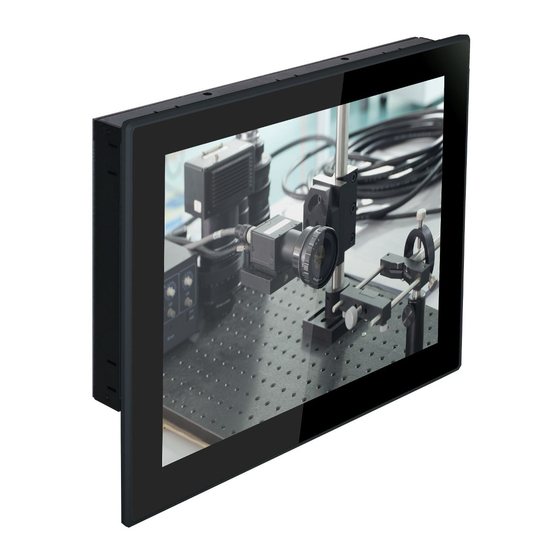
• 15" Touch Panel PC
• Poron foam
• 1 Chassis Panel Mount Bracket
DFI reserves the right to change the specifications at any time prior to
the product's release. For the latest revision and for more details of the
installation process, please refer to the user's manual on the website.
Package Contents
www.dfi.com
1
Advertisement
Table of Contents

Related Manuals for DFI KS150-BT


Summary of Contents for DFI KS150-BT
- Page 1 • Poron foam • 1 Chassis Panel Mount Bracket DFI reserves the right to change the specifications at any time prior to the product's release. For the latest revision and for more details of the installation process, please refer to the user's manual on the website.
- Page 2 Installing the SATA Drive 1. The SATA drive bay is located on the system. SATA drive bay 2. Remove the 4 mounting screws on the HDD bracket and then put them in a safe place for later use. Mounting screw...
- Page 3 3. Insert the SATA drive into the HDD bracket and connect the SATA power/ data connector on the SATA drive to the SATA power/data cable secured on the HDD bracket. SATA drive HDD bracket SATA power/data cable 4. Then, align mounting holes of the SATA drive with mounting holes on the back side of the HDD bracket and use the provided mounting screws to secure the drive in place.
- Page 4 5. Place the SATA drive with the HDD bracket into the system. Tighten the 4 mounting screws you removed in step 2. Mounting screw...
- Page 5 Board Layout and Jumper Settings Digital I/O (JP17) (JP20) CPU Fan DC-in Standby System Power LED (JP18) Clear CMOS Data (JP7) ASMedia Digital I/O Power Select (JP17) ASM1442 Front Digital I/O 3/5/7/9 Output State (JP18) Buzzer Panel Digital I/O 11/13/15/17 Output State (JP20) DVI-I Intel...
- Page 6 Mini PCIe/mSATA Power Select SATA DOM Power Select JP12 +3.3V_standby (Mini PCIe) (default) 1-2 On GND (default) 1-2 On +3.3V (mSATA) 2-3 On 2-3 On Mini PCIe/mSATA Signal Select Auto Power-on Select JP13 1-4-7-10 Power-on via power button (default) 1-2 On PCIe 1 (default) 2-5-8-11 On Power-on via AC power...
Need help?
Do you have a question about the KS150-BT and is the answer not in the manual?
Questions and answers