DFI TPC121 User Manual
Touch panel pc
Hide thumbs
Also See for TPC121:
- Quick manual (4 pages) ,
- User manual (71 pages) ,
- Installation manual (7 pages)

Subscribe to Our Youtube Channel
Related Manuals for DFI TPC121


Summary of Contents for DFI TPC121
- Page 1 TPC121/150/170/190-SB Touch Panel PC User’s Manual A24640503 Chapter 1 Introduction www.dfi .com...
-
Page 2: Copyright
Copyright FCC and DOC Statement on Class A This publication contains information that is protected by copyright. No part of it may be re- This equipment has been tested and found to comply with the limits for a Class A digital produced in any form or by any means or used to make any transformation/adaptation without device, pursuant to Part 15 of the FCC rules. -
Page 3: Table Of Contents
Standby Power LED ..................38 Key Features ....................7 Power Connectors ..................38 Specifications ....................8 Expansion Slots ..................39 Getting to Know the TPC121/150/170/190-SB ......... 12 Front Panel Connector ................39 Mechanical Dimensions ................14 Battery ....................... 40 SDVO Connector ..................40 Chapter 2 - Getting Started .............. -
Page 4: About This Manual
About this Manual Static Electricity Precautions An electronic file of this manual is included in the CD. To view the user’s manual in the CD, in- It is quite easy to inadvertently damage your PC, system board, components or devices even sert the CD into a CD-ROM drive. -
Page 5: About The Package
Safety Precautions About the Package • Use the correct DC input voltage range. The package contains the following items. If any of these items are missing or damaged, please contact your dealer or sales representative for assistance. • Unplug the power cord before removing the system chassis cover for installation or servic- ing. -
Page 6: Chapter 1 - Introduction
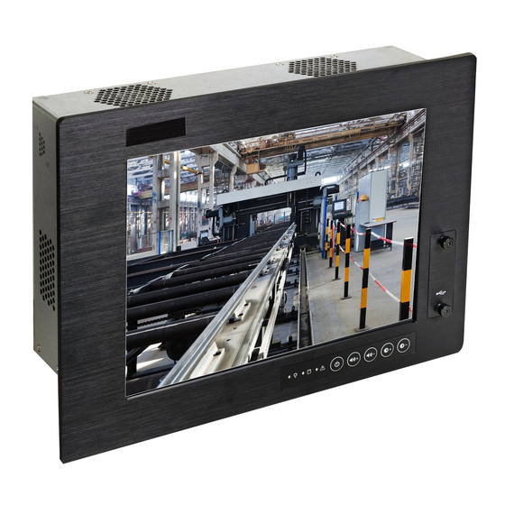
Chapter 1 Chapter 1 - Introduction Overview TPC121 TPC150/TPC170/TPC190-SB Chapter 1 Introduction www.dfi .com... -
Page 7: Key Features
Chapter 1 Key Features TPC121/150/170/190-SB Processor 3rd/2nd Generation Intel ® Core processors Chipset Intel ® H61 Express Chipset 2 LAN ports 2 COM ports Dual Displays HDMI and DVI-I 2 Type A USB 2.0/1.1 ports at the front panel 4 Type A USB 2.0/1.1 ports at the bottom... -
Page 8: Specifications
Chapter 1 Specifi cations TPC121 Processor System • Processors: I/O Ports • Front - 3rd generation Intel Core processors - 2 Type A USB 2.0/1.1 ports ® - 2nd generation Intel Core processors ® - 5 function keys: power, volume, and brightness... - Page 9 Chapter 1 Specifi cations TPC150 Processor System I/O Ports • Front • Processors: - 2 Type A USB 2.0/1.1 ports - 3rd generation Intel ® Core processors - 5 function keys: power, volume, and brightness - 2nd generation Intel Core processors ®...
- Page 10 Chapter 1 Specifi cations TPC170 Processor System I/O Ports • Front • Processors: - 2 Type A USB 2.0/1.1 ports - 3rd generation Intel ® Core processors - 5 function keys: power, volume, and brightness - 2nd generation Intel Core processors ®...
- Page 11 Chapter 1 Specifi cations TPC190-SB Processor System I/O Ports • Front • Processors: - 2 Type A USB 2.0/1.1 ports - 3rd generation Intel ® Core processors - 5 function keys: power, volume, and brightness - 2nd generation Intel Core processors ®...
-
Page 12: Getting To Know The Tpc121/150/170/190-Sb
Chapter 1 Getting to Know the TPC121/150/170/190-SB Front View Bottom View - TPC121 COM 2 Power Switch Built-in antenna Line-in Expansion slots DVI-I 24V DC-in (option) PS/2 Mouse 19~24V DC-in USB 2.0 COM 1 Line-out (standard) PS/2 KB HDMI Mic-in Power Switch Press to power-on or power-off the system. - Page 13 Bottom View - TPC150/TPC170/TPC190-SB Power Switch COM 2 Power Switch COM 2 Line-in Line-in PS/2 Mouse DVI-I 24V DC-in DVI-I Line-out AC power USB 2.0 COM 1 USB 2.0 COM 1 Line-out PS/2 KB HDMI Mic-in Expansion slots PS/2 Mouse HDMI Mic-in Expansion slots...
-
Page 14: Mechanical Dimensions
Chapter 1 Mechanical Dimensions TPC121 TPC150 Top View Top View 103.00 106.00 345.00 34.00 410.00 37.00 248.50 6.00 6.00 306.00 Left View Front View Right View Left View Front View Right View Bottom View 330.00 110.00 90.00 270.00 100.00 75.00 100.00... - Page 15 Chapter 1 TPC170 TPC190-SB Top View Top View 116.00 472.00 106.00 47.00 377.50 6.00 443.78 37.00 339.50 6.00 Left View Front View Right View Left View Front View Right View 364.00 144.00 100.00 100.00 75.00 75.00 Rear View Rear View 144.00 364.00 Chapter 1 Introduction...
- Page 16 Motherboard Dimension 10.16 0.00 22.86 46.94 49.47 64.59 68.97 86.97 104.97 124.47 141.39 153.34 154.94 154.94 159.84 Chapter 1 Introduction www.dfi .com...
-
Page 17: Chapter 2 - Getting Started
• CD-ROM drive (for installing software/drivers) • Screwdriver • Memory module (optional) Installing Devices The following are devices that can be installed in the TPC121/150/170 system. • Memory module • SATA hard drive • Mini PCIe card Configuring the BIOS To get you started, you may need to change configurations such as the date, time and the type of hard disk drive. -
Page 18: Chapter 3 - Installing Devices
5. The memory socket, expansion slots, Mini PCIe slot and SATA drive bay are readily acces- sible after removing the chassis cover. Removing the Chassis Cover TPC121/TPC190-SB 1. Make sure the system and all other peripheral devices connected to it has been powered- off. -
Page 19: Installing An Sodimm
Chapter 3 Chapter 3 Installing an SODIMM 4. Grasping the module by its edges, position the module above the socket with the notch in the socket aligned with the key on the module. Apply fi rm even pressure to each end of the module until it slips down into the socket. -
Page 20: Installing A Sata Drive
Chapter 3 Chapter 3 Installing a SATA Drive 2. Remove the mounting screws that secure the HDD bracket to the drive bay. TPC121/TPC190-SB 1. Locate the SATA drive bay in the chassis. TPC121/TPC190-SB Mounting Screw SATA drive bay TPC150/TPC170 TPC150/TPC170... - Page 21 Chapter 3 Chapter 3 3. Align the mounting holes of the SATA drive with the mounting holes on the HDD bracket and then use the provided mounting screws to secure the drive in place. SATA drive Mounting hole HDD bracket Mounting screws Mountin Mounting screw...
-
Page 22: Installing A Mini Pcie Card
Chapter 3 Chapter 3 Installing a Mini PCIe Card Latch 1. Locate the two Mini PCIe slots on the chassis. SATA data connector SATA power connector Mini PCIe slot Mini PCIe slot 2. The latch is used to lock the Mini PCIe card into position. Insert the latch into the mounting holes and then push the latch down until the clips at each end of the latch lock into position. -
Page 23: Removing The Latch
Chapter 3 Chapter 3 3. The system board is equipped with a Mini PCIe slot. The Mini PCIe slot supports half length Mini PCIe card. Note the key on the slot. The key ensures the Mini PCIe card can be plugged into the slot in only one direction. -
Page 24: Installing The Mini Pcie Card
Chapter 3 Chapter 3 Installing the Mini PCIe Card Installing the PCI and PCIe x1 Expansion Cards 1. The PCI and PCIe x1 slots on the riser card are used to install the expansion cards. To install 1. Grasping the Mini PCIe card by its edges, align the card into the slot at an approximately 30 degrees angle. -
Page 25: Connecting Cables To Terminal Blocks
Chapter 3 Chapter 3 Connecting Cables to Terminal Blocks 2. Plug the terminal block into the DC-in connector and then tighten the screws to secure the terminal block in place. 1. Insert the cable end of the power adaptor to the terminal block. To fi rmly fi x the cable into the terminal block, use a screwdriver to clamp down the wires to the screw that is in the terminal block. -
Page 26: Chapter 4 - Jumper Settings
Chapter 4 Chapter 4 - Jumper Settings PS/2 Power Select Clear CMOS 1-2 On: +5V 2-3 On: (default) +5V_standby 1-2 On: Normal (default) 2-3 On: Clear CMOS Data JP2 is used to select the power of the PS/2 keyboard and PS/2 mouse ports. Selecting +5V_ standby will allow you to use the PS/2 keyboard or PS/2 mouse to wake up the system. -
Page 27: Usb Power Select
Chapter 4 USB Power Select Power-on Select USB 0-1/8-9 (JP4) 1-2 On: Power-on via power button 1-2 On: +5V 2-3 On: (default) (default) +5V_standby USB 2-3/10-11 (JP7) 2-3 On: Power-on via AC power; or Power-on via WOL after G3 1-2 On: +5V 2-3 On: (default) +5V_standby... -
Page 28: Com 1 Rs232/422/485 Select
Chapter 4 COM 1 RS232/RS422/RS485 Select COM 1 Signal Select JP1 (for COM 1) is used to configure the COM port to RS232, RS422 (Full Duplex) or RS485. The pin function of the COM ports will vary according to the jumper’s setting. 1-3 On: Pin-9 3-5 On: Pin-9 2-4 On: Pin-1... -
Page 29: Front Audio Or Audio Amplifier Select
Chapter 4 Front Audio or Audio Amplifier Select 1-3, 2-4 On: 3-5, 4-6 On: Front audio Audio Amplifier (default) JP5 is used to configure front audio or audio amplifier select. Chapter 4 Jumper Settings www.dfi .com... -
Page 30: Chapter 5 - Ports And Connectors
Chapter 5 Chapter 5 - Ports and Connectors USB Ports Front Panel I/O Port USB allows data exchange between your computer and a wide range of simultaneously acces- sible external Plug and Play peripherals. The system board is equipped with 2 USB 2.0/1.1 ports. •... -
Page 31: Bottom Panel I/O Ports
Chapter 5 Bottom Panel I/O Ports PS/2 Mouse and PS/2 Keyboard Ports COM 2 PS/2 Mouse Line-in DVI-I PS/2 K/B PS/2 Mouse Line-out USB 2.0 COM 1 PS/2 KB HDMI Mic-in The bottom panel I/O ports consist of the following: •... -
Page 32: Rj45 Lan Ports
Chapter 5 RJ45 LAN Ports USB Ports LAN 1 LAN 2 USB 1 USB 10-11 USB 0 USB 2-3 USB 2.0 N. C. +Data +Data -Data -Data USB 8 USB 9 USB 2.0 Features USB allows data exchange between your computer and a wide range of simultaneously acces- sible external Plug and Play peripherals. -
Page 33: Graphics Interfaces
Chapter 5 Graphics Interfaces Wake-On-USB Keyboard/Mouse The Wake-On-USB Keyboard/Mouse function allows you to use a USB keyboard or USB mouse The display ports consist of the following: to wake up a system from the S3 (STR - Suspend To RAM) state. To use this function: •... -
Page 34: Com (Serial) Ports
Chapter 5 COM (Serial) Ports Audio Line-in Line-out Mic-in COM 2: RS232 Rear audio COM 1: Front audio RS232/422/485 The pin function of COM 1 port will vary according to JP1’s setting. Refer to “COM1 RS232/ RS422/RS485 Select” in this chapter for more information. The serial ports are asynchronous communication ports with 16C550A-compatible UARTs that can be used with modems, serial printers, remote display terminals, and other serial devices. -
Page 35: I/O Connectors
Chapter 5 I/O Connectors BIOS Setting Configure the onboard audio in the Chipset menu (“South Bridge” submenu) of the BIOS. SATA (Serial ATA) Connectors Refer to chapter 3 for more information. Driver Installation Install the audio driver. Refer to chapter 8 for more information. SATA 2.0 3Gb/s Features •... -
Page 36: Digital I/O Connector And Digital I/O Power Connector
Chapter 5 Digital I/O Connector Audio Amplifier Connector Digital I/O Power Connector Digital I/O power Out L- Digital I/O Out R+ Audio Amplifier Out R- Out L+ The audio amplifier connector which has amplifying feature is used to connect external speak- ers. -
Page 37: Chassis Intrusion Connector
Chapter 5 Chassis Intrusion Connector Cooling Fan Connectors Ground System_fan 2 Power Sense Signal Ground System_fan 1 Ground Power Sense Speed Control Sense Power CPU fan Ground The board supports the chassis intrusion detection function. Connect the chassis intrusion The fan connectors are used to connect cooling fans. The cooling fans will provide adequate sensor cable from the chassis to this connector. -
Page 38: Standby Power Led
Chapter 5 Standby Power LED Power Connectors 10 20 Standby Power LED +12V ATX power 5VSB PW-OK PS-ON Ground Ground 3.3V -12V 3.3V 3.3V +12V +12V ATX 12V Use a power supply that complies with the ATX12V Power Supply Design Guide Version 1.1. This LED will lit red when the system is in the standby mode. -
Page 39: Expansion Slots
Chapter 5 Expansion Slots Front Panel Connector Mini PCI Express PWR-LED HDD-LED RESET-SW PWR-BTN PCI Express x16 PCI Express x16 Slot HDD-LED - HDD LED The PCI Express x16 slot is an interface for the X100-3PE2 riser card. The X100-3PE2 fea- This LED will light when the hard drive is being accessed. -
Page 40: Battery
Chapter 5 Battery SDVO Connector Battery SDVO The SDVO connector is used to connect the optional SDVO-LVDS daughterboard. The lithium ion battery powers the real-time clock and CMOS memory. It is an auxiliary source Pins Pin Assignment Pins Pin Assignment of power when the main power is shut off. -
Page 41: Sdvo-Lvds Daughterboard (Optional)
Chapter 5 SDVO-LVDS Daughterboard (optional) Power Select for the LCD Panel Features • Chrontel CH7308B • Supports 18/24-bit 1600x1200 LVDS panel (default 1280x1024) 1-2 On: +12V • 1 LVDS LCD panel connector • 1 LCD/Inverter power connector • SDVO interface •... - Page 42 Chapter 5 LVDS LCD Panel and LCD Inverter Power Connectors LVDS LCD Panel Connector Pins Function Pins Function LVDS_Out3+ LVDS_Out7+ LVDS_Out3- LVDS_Out7- LCD/Inverter power LVDS_Out2+ LVDS_Out6+ LVDS_Out2- LVDS_Out6- LVDS_Out1+ LVDS_Out5+ LVDS LCD panel LVDS_Out1- LVDS_Out5- The system board allows you to connect a LCD Display Panel by means of the LVDS LCD panel connector and the LCD/Inverter power connector.
-
Page 43: Installing The Sdvo-Lvds Daughterboard Onto The Motherboard (Optional)
Chapter 5 LCD/Inverter Power Connector Installing the SDVO-LVDS Daughterboard onto the Motherboard (optional) Pins Function Important: The motherboard used in this section is for reference purpose only and may not resemble your motherboard. These illustrations are mainly to guide you on how to install SDVO-LVDS onto the motherboard of your choice. - Page 44 Chapter 5 3. While supporting the mounting screw at the bottom, from the top side of the board, fasten a bolt into the screw. SDVO connector on the motherboard 5. Press the daughterboard down firmly until it is completely seated on the SDVO connector Bolt of the motherboard.
-
Page 45: Chapter 6 - Mounting Options
Chapter 6 Chapter 6 - Mounting Options 3. Attach the other bracket (wall mount bracket 2) to the rear of the Panel PC. Wall Mount The wall mount kit includes the following: • 2 Wall mount brackets • Bracket screws Mounting screw Wall mount bracket 2 Hooks... -
Page 46: Panel Mount
Chapter 6 Panel Mount The panel mounting kit includes the following: • 10 mounting clamps (TPC121 and TPC150) • 12 mounting clamps (TPC170 and TPC190-SB) 1. Select a place on the panel where you will mount the Panel PC. 2. Cut out a shape on the panel that corresponds to the Panel PC’s rear dimensions. - Page 47 Chapter 6 3. Stick the poron foam on the rear panel. 6. The fi rst and second clamps must be positioned and secured diagonally prior to mounting the rest of the clamps. Tighten the clamp’s screw using an electric screwdriver until the white plastic cap touches the panel.
-
Page 48: Chapter 7 - Bios Setup
Chapter 7 Chapter 7 - BIOS Setup Legends Overview Keys Function The BIOS is a program that takes care of the basic level of communication between the CPU and peripherals. It contains codes for various advanced features found in this system board. Moves the highlight left or right to select a menu. -
Page 49: Ami Bios Setup Utility
Chapter 7 AMI BIOS Setup Utility Advanced Main The Advanced menu allows you to configure your system for basic operation. Some entries are defaults required by the system board, while others, if enabled, will improve the performance of your system or let you set some features according to your preference. The Main menu is the first screen that you will see when you enter the BIOS Setup Utility. - Page 50 Chapter 7 ACPI Power Management Configuration PC Health Status This section is used to configure the ACPI Power Management. This section displays the SIO hardware health monitor. Aptio Setup Utility - Copyright (C) 2011 American Megatrends, Inc. Aptio Setup Utility - Copyright (C) 2011 American Megatrends, Inc. Advanced Advanced System Hardware Monitor...
- Page 51 Chapter 7 Boundary 1 to Boundary 4 CPU Configuration The range is from 0-127. This section is used to configure the CPU. It will also display the detected CPU information. Speed Count 1 to Speed Count 5 Aptio Setup Utility - Copyright (C) 2011 American Megatrends, Inc. The range is from 1-100.
- Page 52 Chapter 7 SATA Configuration USB Configuration This section is used to configure SATA functions. This section is used to configure USB. Aptio Setup Utility - Copyright (C) 2011 American Megatrends, Inc. Aptio Setup Utility - Copyright (C) 2011 American Megatrends, Inc. Advanced Advanced SATA Controller(s)
- Page 53 Chapter 7 F71879 Super IO Configuration Serial Port 1 Configuration to Serial Port 2 Configuration This section is used to configure the I/O functions supported by the onboard Super I/O chip. Aptio Setup Utility - Copyright (C) 2011 American Megatrends, Inc. Advanced Aptio Setup Utility - Copyright (C) 2011 American Megatrends, Inc.
- Page 54 Chapter 7 Chipset Network Stack Configures relevant chipset functions. Aptio Setup Utility - Copyright (C) 2011 American Megatrends, Inc. Advanced Network Stack [Enabled] Enable or disable UEFI Aptio Setup Utility - Copyright (C) 2011 American Megatrends, Inc. Ipv4 PXE Support [Enabled] network stack.
- Page 55 Chapter 7 South Bridge PCI Express Configuration Aptio Setup Utility - Copyright (C) 2011 American Megatrends, Inc. Aptio Setup Utility - Copyright (C) 2011 American Megatrends, Inc. Chipset Chipset PCI Express Confi guration Control the PCI Express Intel PCH RC Version 1.5.0.0 PCI Express Coniguration Root Port...
- Page 56 Chapter 7 North Bridge USB Configuration Aptio Setup Utility - Copyright (C) 2011 American Megatrends, Inc. Aptio Setup Utility - Copyright (C) 2011 American Megatrends, Inc. Chipset Chipset System Agent Bridge Name IvyBridge Check to enableVT-d USB Confi guration Control the USB EHCI 1.5.0.0 function on MCH.
- Page 57 Chapter 7 Graphics Configuration LCD Control Aptio Setup Utility - Copyright (C) 2011 American Megatrends, Inc. Aptio Setup Utility - Copyright (C) 2011 American Megatrends, Inc. Chipset Chipset LCD Control Select the Video Device Graphics Confi guration Select which of IGFX/ which will be activated IGFX VBIOS Version 2137...
- Page 58 Chapter 7 Boot Enabled PEG To enable or disable the PEG. Aptio Setup Utility - Copyright (C) 2011 American Megatrends, Inc. Main Advanced Chipset Boot Security Save & Exit Memory Information Boot Confi guration Number of seconds to Setup Prompt Timeout wait for setup activation Bootup NumLock State [On]...
- Page 59 Chapter 7 Security CSM Parameters Aptio Setup Utility - Copyright (C) 2011 American Megatrends, Inc. Aptio Setup Utility - Copyright (C) 2011 American Megatrends, Inc. Main Advanced Chipset Boot Security Save & Exit Main Advanced Chipset Boot Security Save & Exit This option controls if Launch CSM [Enabled]...
-
Page 60: Updating The Bios
Chapter 7 Save & Exit Updating the BIOS To update the BIOS, you will need the new BIOS file and a flash utility, AFUDOS.EXE. Please Aptio Setup Utility - Copyright (C) 2011 American Megatrends, Inc. contact technical support or your sales representative for the files. Main Advanced Chipset... -
Page 61: Notice: Bios Spi Rom
Chapter 7 Notice: BIOS SPI ROM 1. The Intel Management Engine has already been integrated into this system board. Due to ® the safety concerns, the BIOS (SPI ROM) chip cannot be removed from this system board and used on another system board of the same model. 2. -
Page 62: Chapter 8 - Supported Software
Chapter 9 Chapter 8 Chapter 8 - Supported Software Auto Run Pages (for Windows XP) The CD that came with the system board contains drivers, utilities and software applications required to enhance the performance of the system board. Insert the CD into a CD-ROM drive. The autorun screen (Mainboard Utility CD) will appear. If after inserting the CD, “Autorun”... - Page 63 Chapter 9 Chapter 8 Intel Chipset Software Installation Utility 3. Go through the readme document for more installa- tion tips then click Next. The Intel Chipset Software Installation Utility is used for updating Windows INF files so that ® the Intel chipset can be recognized and configured properly in the system. To install the utility, click “Intel Chipset Software Installation Utility”...
- Page 64 Chapter 9 Chapter 8 Microsoft .NET Framework 3.5 (for Windows XP only) 3. Click Exit. Note: Before installing Microsoft .NET Framework 3.5, make sure you have updated your Windows XP operating system to Service Pack 3. To install the driver, click “Microsoft .NET Framework 3.5” on the main menu. 1.
- Page 65 Chapter 9 Chapter 8 Microsoft DirectX 9.0C (for Windows XP only) Intel Graphics Drivers To install the driver, click “Microsoft DirectX 9.0C” on the main menu. To install the driver, click “Intel Graphics Drivers” on the main menu. 1. Setup is now ready to 1.
- Page 66 Chapter 9 Chapter 8 Audio Drivers 3. Go through the readme document for system re- quirements and installation To install the driver, click “Audio Drivers” on the main menu. tips then click Next. 1. Setup is ready to install the driver.
- Page 67 Chapter 9 Chapter 8 Intel LAN Drivers 4. Click Install to begin the installation. To install the driver, click “Intel LAN Drivers” on the main menu. 1. Setup is ready to install the driver. Click Next. 5. After completing installa- tion, click Finish.
- Page 68 Chapter 9 Chapter 8 Intel Management Engine Drivers 3. Setup is currently installing the driver. After installation has completed, click Next. To install the driver, click “Intel Management Engine Drivers” on the main menu. 1. Setup is ready to install the driver.
- Page 69 Chapter 9 Chapter 8 MyGuard Hardware Monitor 6. Click Install to begin instal- lation. 1. Locate for the MyGuard folder in the provided disc. 2. In the MyGuard folder, right-click on the “setup” file. 3. Select Run As Administrator. 4. Double-click Setup. 7.
- Page 70 Chapter 8 DFI Utility 3. Enter “User name” (SB102) and “Organization” information DFI Utility provides information about the board, Watchdog, DIO, and Backlight. then click “Next”. To access the utility, click “DFI Utility” on the main menu. Note: If you are using Windows 7, you need to access the operating system as an administrator to be able to install the utility.
- Page 71 Chapter 9 Chapter 8 PenMount Windows Universal Driver The DFI Utility icon will appear on the desktop. Double-click the icon to open the utility. To install the touch screen driver, click “PenMount Windows Universal Driver” on the main menu. 1. Setup is ready to install the driver.
- Page 72 Chapter 9 Chapter 8 TPC Series Hotkey Driver 4. Setup is currently installing the utility. To install the function keys driver, click on “TPC Series Hotkey Driver” on the main menu. 1. InstallShield Wizard Setup is preparing to install, please wait. 5.
- Page 73 Chapter 9 Chapter 8 4. Setup is currently installing Note: the utility. The following illustrations are the TPC series hotkey guide for you to adjust the brightness of your touch panel. Please follow the steps below to complete the setting. 1.
- Page 74 Chapter 9 Chapter 8 Adobe Acrobat Reader 9.3 4. Press two hotkeys in the red circle (as the photo displays below) at the same time to switch the backlight brightness of day and night mode. To install the reader, click “Adobe Acrobat Reader 9.3” on the main menu. 1.
-
Page 75: Chapter 9 - Audio Configuration
Chapter 9 Chapter 9 Chapter 9 - Audio Configuration 4. When the Connector Set- tings dialog box appears, Configuring Speakers (for Windows XP only) check the “Disable front panel jack detection” box. The following illustrations use the Windows XP operating system to configure the speaker. Then click “OK”. - Page 76 Chapter 9 Chapter 9 Configuring Speakers (for Windows 7 only) 4. Click “ ” for testing. The following illustrations use the Windows 7 operating system to configure the speaker. 1. After installing the audio driver, go the the Control Panel and double-click the “Realtek HD Audio Manag- er“...
-
Page 77: Appendix A - Smart Fan Setting Guide
Appendix A Appendix A - Smart Fan Setting Guide 2. Smart fan has 4 boundaries and 5 Speed Count. For below configuration, Boundary 1 to Boundary 4 refers to the temperature; and Speed Entering the Smart Fan Function Count 1 to Speed Count 5 refers to the value of the speed count. The BIOS Setup Utility can only be operated from the keyboard and all commands are key- Aptio Setup Utility - Copyright (C) 2011 American Megatrends, Inc. - Page 78 Appendix A 3. Speed Count and System Fan speed (rpm) matrix. Speed Count System Fan Speed (rpm) Speed Count System Fan speed (rpm) 3100 4600 3350 4650 3500 4900 3650 4950 3800 5000 3900 5050 4050 5100 4150 5150 Appendix A Smart Fan Setting Guide www.dfi...
-
Page 79: Appendix B - Watchdog Sample Code
Appendix B Appendix B - Watchdog Sample Code ;Software programming example: ;--------------------------------------------- ;(1) Enter Super IO Confi guration mode ;--------------------------------------------- DX,2EH AL,87H DX,AL DX,AL ;------------------------------------------------------------------------------------------- ;(2) Confi guration Logical Device 7, register CRF5/CRF6 (WDT Control /WDT timer) ;------------------------------------------------------------------------------------------- DX,2EH AL,07H ;Ready to Program Logical Device DX,AL DX,2FH... -
Page 80: Appendix C - System Error Message
Appendix C Appendix C - System Error Message Hard Disk(s) fail (20) When the BIOS encounters an error that requires the user to correct something, either a beep HDD initialization error. code will sound or a message will be displayed in a box in the middle of the screen and the message, PRESS F1 TO CONTINUE, CTRL-ALT-ESC or DEL TO ENTER SETUP, will be shown in Hard Disk(s) fail (10) the information box at the bottom. -
Page 81: Appendix D - Troubleshooting Checklist
Appendix D Appendix D - Troubleshooting Checklist The picture seems to be constantly moving. Troubleshooting Checklist 1. The monitor has lost its vertical sync. Adjust the monitor’s vertical sync. This chapter of the manual is designed to help you with problems that you may encounter 2. -
Page 82: Hard Drive
Appendix D Hard Drive System Board 1. Make sure the add-in card is seated securely in the expansion slot. If the add-in card is Hard disk failure. loose, power off the system, re-install the card and power up the system. 1.
Need help?
Do you have a question about the TPC121 and is the answer not in the manual?
Questions and answers