
Related Manuals for Acculab ATL-224


Summary of Contents for Acculab ATL-224
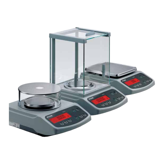
- Page 1 Operating Instructions ACCULAB ATILON Electronic Analytical and Precision Balances 98648-015-55...
-
Page 2: Table Of Contents
Contents 3 Warnings and Safety Precautions 44 ISO/GLP-compliant Printout/Record 4 Getting Started 46 Data Interface 5 Installation 47 Troubleshooting Guide 11 Operation 48 Care and Maintenance 11 Display and Operating Elements 12 Basic Weighing Function 49 Recycling 14 Calibration/Adjustment 50 Overview 17 Configuration (Operating Menu) 51 Specifications 17 Functions of the Keys during Configuration... -
Page 3: Warnings And Safety Precautions
Warnings and Safety Precautions Safety – Connect only Acculab accessories, as these are optimally § To prevent damage to the equipment, please read these designed for use with your Atilon balance. The operator shall operating instructions carefully before using the balance. -
Page 4: Getting Started
The control seal consists of a sticker. If the seal is broken, – AC adapter the verification becomes null and void and the balance must be re-verified. Additional equipment supplied with models ATL-224, -124: – Sliding-door draft shield – Drip/breeze ring – Draft shield base plate Additional equipment supplied with models ATL-623, -423, -153: –... -
Page 5: Installation
Installation Setting Up the Balance Instruments with sliding-door draft shield: § Place components inside the chamber in the following order: – Draft shield base plate – Drip/breeze ring – Pan support – Weighing pan Instruments with a round glass draft ring: §... - Page 6 Connecting the Balance to AC Power/Safety Precautions Use only original Acculab AC adapters. For use within – Europe: part no. 6971412 – U.S./Canada: part no. 6971413 § 1) Connect the angle plug to the balance § 2) Connect the AC adapter to the wall outlet (mains)
- Page 7 NOTE: This equipment has been tested and found to If you have a Class B digital device, please read and follow comply with the limits pursuant to part 15 of FCC Rules. the FCC information given below: These limits are designed to provide reasonable protection “However, there is no guarantee that interference will not against harmful interference.
- Page 8 Connecting Electronic Peripheral Devices § Make sure to unplug the balance from AC power before you connect or disconnect a peripheral device (printer or computer) to or from the interface port. Warmup Time To ensure accurate results, the balance must warm up before operation as follows: –...
- Page 9 Below-Balance Weighing A port for a below-balance weighing hanger is located on the bottom of the balance. $ Below-balance weighing is not permitted in legal metrology. § Open cover plate on the bottom of the balance. Important: set the balance on its side to access the cover plate. DO NOT turn the balance upside-down.
- Page 10 Leveling the Balance Purpose: – To compensate for unevenness at the place of installation Always level the balance again any time after it has been moved to a different location. Only the 2 front feet are adjusted to level the balance. §...
-
Page 11: Operation
Operation Overview of Display Elements Pos. Designation Pos. Designation Weight unit Busy symbol: command is being processed (for example, Menu level indicator “Wait for stability icon); after you turn on the power, A will be displayed until you press a key Symbol: “GLP printing mode active”... -
Page 12: Basic Weighing Function
Basic Weighing Function Features Using Verified Balances as Legal Measuring – Taring the balance Instruments in the EU*: – Printing weights The type-approval certificate for verification applies only to non-automatic weighing instruments. For automatic Preparation operation with or without auxiliary measuring devices, you §... - Page 13 Example Simple Weighing Step Key (or instruction) Display/Printout Balance in standby mode 10:32:30 1. Switch on the balance (ON/OFF) 0.0 g Self-test is performed, followed by automatic initial tare function. 2. Place container on weighing pan 11.5 g (in this example: 11,5 g). 3.
-
Page 14: Calibration/Adjustment
Calibration and Adjustment Purpose To block calibration/adjustment: Calibration is the determination of any difference between – Select Cal.-Adj.-blocked in the menu the measured value displayed and the true weight (mass) – Close the menu access switch on the back of the balance of a sample. - Page 15 Internal Calibration/Adjustment (Only on ATL…-I und ATL…-V models) Set the following parameters: SETUP - Waage - CAL.Just. - Cal.Int. (menu code 1.1. 9. 4) The built-in motorized calibration weight is applied and removed automatically for internal calibration. Step Key (or instruction) Display 1.
- Page 16 External Calibration Parameters (changes in factory settings): SETUP - Waage - CAL.Just. - Cal.Ext. (menu code 1.1. 9. 1) The required calibration weight is configured at the factory (see “Specifications”) Step Key (or instruction) Display 1. Unload and tare the balance (TARE) 0.0 g 2.
-
Page 17: Configuration (Operating Menu)
Configuration (Operating Menu) You can configure the balance; i.e., adapt it to individual requirements. Functions of the Keys during Configuration Symbol Function (MENU)* Scroll through menu items Press and hold > (ENTER) One menu level lower ↵ (ENTER) Confirm menu item (CLEAR) Save settings and exit menu from any position Press and hold... -
Page 18: Menu Navigation; Example: Setting The Language
Menu Navigation Example: Setting the Language Step Key (or instruction) Display 1. Open the menu: (MENU)* (hold) Applic. In weighing mode: first menu item is shown 2. Scroll upward within the Repeatedly: (MENU)* Input menu level; after the last menu code, the first languag. -
Page 19: Parameter Settings: Menu
Parameter Settings: Menu Level 1 Level 2 Level 3 Menu code Ambient Ambient conditions 1. 1. 1. Setup Bal.Scal. Balance parameters app.fil. Application filter 1. 1. 2. Stab.Rng. Stability range 1. 1. 3. Taring Taring 1. 1. 5 AutoZer. Auto zero 1. -
Page 20: Parameter Settings: Overview
Parameter Settings: Overview ο = Factory setting √ = User-defined setting Level 1 Level 2 Level 3 Level 4 Menu code V.Stable Very stable 1. 1. 1. 1 Setup Bal.Scal. Ambient ο Stable Balance Ambient 1. 1. 1. 2 parameters conditions 1. - Page 21 Level 1 Level 2 Level 3 Level 4 Menu code 1. 5. 1. 3 Setup Interf. Baudrate ο 1200 Interface 1. 5. 1. 4 1. 5. 1. 5 2400 1. 5. 1. 6 4800 1. 5. 1. 7 9600 1. 5. 1. 8 19200 ο...
-
Page 22: Print Key
Level 1 Level 2 Level 3 Level 4 Menu code 1. 6. 5. 1 Setup Prnt.Out Prt.Init. ο All All parameters Printing Printing appli- 1. 6. 5. 2 cation parameters MainPar. Main parameters 1. 6. 5. 2 Format Line 16 Char. 16 characters (w/o ID) 1. - Page 23 Level 1 Level 2 Level 3 Level 4 Menu code 2. 1. Applic. Weigh ο All Applic. 2. 2. 2. 1 Unit Disp.Dig. programs Toggle units Display 2. 2. 2. 2 Minus 1 accuracy ο Disp.Acc. Display accuracy 2. 3. 1. 1 Counting Resolut.
-
Page 24: Input: Id Number, Date And Time
Input: ID number, Date and Time Level 1 Level 2 Level 3 Menu Code ID input for ISO/GLP compliant data record; 3. 1. Input ID No. Input 7 characters max. Permitted characters: 0 to 9; A to Z; dash/hyphen; space Menu item for setting the date 3. - Page 25 Example: ID No., Date and Time Step Key (or instruction) Display 1. Open the menu:In weighing mode; (MENU)* hold APPLIC. first menu item is displayed 2. Select “Input” (MENU)* Input 3. Select input for ID no. twice (ENTER) ID NO. 4.
-
Page 26: Application Programs
Device Information Level 1 Level 2 Level 3 Example Menu code Show software version 4. 1. InFormation version rel.36.03 Show serial number 4. 2. Ser. No. 10801234 To toggle focus between upper and lower display sections, press (MENU)* Show model designation 4. -
Page 27: Counting
Counting Changing the Reference Sample Quantity Display symbol: Activate function: Press the (MENU)* key Purpose Select the desired reference sample quantity (1 to 100): With the Counting program you can determine the number In increments of 1: Press the (MENU)* key briefly of parts that each have approximately equal weight. - Page 28 Example : Counting parts of equal weight Parameter: Applic. - Count. (menu code 2. 3.) Step Key (or instruction) Display/Data output 1. Place empty container 22.6 on the balance 2. Tare the balance (TARE) 3. Add reference sample quantity to container (in this example: 20 pcs) 4.
-
Page 29: Weighing In Percent
Weighing in Percent Changing the Reference Percentage Display symbol: Activate function: Press the (MENU)* key Purpose Select the desired reference (1 to 100): This application program allows you to obtain weight read- In increments of 1: Press the (MENU)* key briefly outs in percent which are in proportion to a reference In increments of 10: Press and hold the (MENU)* key. - Page 30 Example: Determining residual weight in percent Parameter settings: Applic. Percent (menu code 2. 4.) Reference percentage: Ref 100% Step Key (or instruction) Display/Data output 1. Tare the balance (TARE) 0.0 g 2. Place sample equal to 100% on the balance (in this example: 111.6 g) 3.
-
Page 31: Calculation
Calculation Display symbol: C Setting the Factor or Divisor Activate function: Purpose Press the (MENU)* key With this application program you Select a number of up to 7 digits and, if needed, can calculate weight value using a multiplier or divisor. This one decimal point (0.000001 to 9999999): can be used, for example, to determine the weight per unit In increments of 1: Press the (MENU)* key briefly... - Page 32 Example: Calculating the weight per unit area of paper: An A4 sheet of paper is used in this example, with surface dimensions of 0.210 m + 0.297 m = 0.06237 m . To determine the weight per unit area, the total weight is divided by the surface. Parameter settings: Applic.
-
Page 33: Animal Weighing/Averaging
Animal Weighing/Averaging Display symbol: V Changing the Number of Subweighing Operations Purpose Activate function: Use this program to determine the weights of unstable Press the (MENU)* key samples (e.g., live animals) or to determine weights under Select the desired number of unstable ambient conditions. - Page 34 Example: Determining animal weight with automatic start and 20 subweighing operations (measurements) Parameter settings: Applic. AnimalW. (menu code 2. 7.) Step Key (or instruction) Display/Data output 1. Place animal weighing bowl on the balance 22.6 g 2. Tare the balance (TARE) 0.0 g 3.
-
Page 35: Net-Total Formulation
Net-total Formulation Display symbol: R Features – Weigh up to 99 components from “0” to a defined total Purpose component weight. With this application program you can weigh in individual components either by their individual weight or by the total –... - Page 36 Example: Counting parts into a container Parameter settings: Applic.-Net-Tot (menu code 2. 5.) Step Key (or instruction) Display/Data output 1. Place empty container on the balance. 65.0 g 2. Tare the balance (TARE) 0.0 g 3. Add first component + 120.5 g 4.
-
Page 37: Totalizing
Totalizing Display symbol: R Features – Totalizing memory for up to 99 values Purpose With this application program you can add values from suc- – Store component weights (printout shows cessive, mutually independent weight values to a total that with automatic printout “Comp xx”... - Page 38 Example: Totalizing weight values Parameter settings: Applic. Total Comp.Prt On (Code 2. 6. 1. 2) Step Key (or instruction) Display/Data output 1. Tare the balance (TARE) 0.0 g 2. Place sample balance + 380.0 g (in this example: 380 g) 3.
-
Page 39: Density Determination
Density Determination Display symbol: W Printout for Density Determination : Weight in air 20.0 g Purpose : Weight in liquid 15.0 g This application program lets you determine the density of : Result: density 4.0 o solid substances using the buoyancy method. You can have of the sample results displayed with one decimal place, or no decimal places: see “Configuration”... - Page 40 Example: Determining the density of a solid sample. Parameter settings: Applic.-Density-Dec.Plcs-1 Dec. Pl (menu code 2. 9. 1. 2) Step Key (or instruction) Display/Data output 1. Attach sample holder to suspension wire 2. Tare the balance (TARE) 0.0 g 3. Start application program (ENTER) 4.
-
Page 41: Mass Unit Conversion
Mass Unit Conversion Purpose Features With this application program you can change the weight – Set the basic unit and display accuracy in the Setup menu: value displayed from the basic weight unit to any of 4 see “Configuration.” application weight units (see table on next page). –... - Page 42 Example: Change display from the basic unit (in this example, grams [g]) to pounds [lb] and then to Troy ounces [ozt]. Set the following parameters: Applic. Unit (Code 2. 2.) Step Key (or instruction) Display Preparation: 1 Begin selection of an application weight unit (MENU)* None 2.
- Page 43 The following weight units are available in your Atilon balance (in legal metrology, only units permitted by national law are available): Menu item Unit Conversion factor Display symbol 1) UserDef. Grams 1,00000000000 2) Grams (factory setting) Grams 1.00000000000 3) Kilogr. Kilograms 0.00100000000 4) Carats...
-
Page 44: Iso/Glp-Compliant Printout/Record
ISO/GLP-compliant Printout/Record Features – Line format for printout: include data ID codes You can have device information, ID texts and date and (22 characters; factory setting): time printed before (GLP header) and after (GLP footer) Setup Prnt.Out Format 22 Char. the values of a weighing series. - Page 45 The ISO/GLP-compliant printout can contain the following lines: Dotted line -------------------- Date/time (beginning of measurement) 17-Aug-2006 10:15 Balance manufacturer ACCULAB Model Mod. ATL-8201 Balance serial number Ser. no. 10105355 Software version Ver. no. 00-36-01 2690 923 Dotted line -------------------- Measurement series no.
-
Page 46: Data Interface
The many and versatile properties of these balances can be Female Interface Connector: fully utilized for printing out records of the results when you connect your balance to a Acculab data printer. The record- ing capability for printouts makes it easy for you to work in compliance with ISO/GLP. -
Page 47: Troubleshooting Guide
Move the object that is the weighing pan touching the weighing pan err 54, typical Weighing system defect Contact Acculab dealer Cannot store data: Increase load App.err. Load on weighing pan too light or no sample on pan while application is active... -
Page 48: Care And Maintenance
§ Repair work must be performed by trained service technicians. Any attempt by untrained persons to perform repairs may result in considerable hazards for the user. If the instrument requires repairs, please contact your Acculab dealer. Cleaning § Unplug the AC adapter from the wall outlet (mains supply). If you have an inter- face cable connected to the balance port, unplug it from the port. -
Page 49: Recycling
Acculab dealer. calibrated multimeter In countries that are not members of the European Econom- ic Area (EEA) or where no Acculab dealers are located, please contact your local authorities or a commercial disposal operator. -
Page 50: Overview
Overview Specifications Built-in motorized All ATL...-I and ATL...-V models calibration weight AC power source/power AC adapter 230 V or 115 25 V, requirements, voltage, frequency +15% to – 20%, 48 – 60 Hz Power consumption maximum 16; typical 8 (STNG6) Approx. - Page 51 Specifications for Individual Models Model ATL-224, ATL-224-I ATL-124, ATL-124-I ATL-84, ATL-84-I Weighing capacity Readability 0.0001 0.0001 0.0001 Tare range (subtractive) Repeatability <± g 0.0001 0.0001 0.0001 (std. deviation) Linearity <± g 0.0002 0.0002 0.0002 Response time (average) –6 Sensitivity drift within +10 to +30°C 2 ·...
- Page 52 Specifications for Individual Models Model ATL-6202, ATL-4202, ATL-2202, ATL-822, ATL-6202-I ATL-4202-I ATL-2202-I ATL-822-I Weighing capacity 6200 4200 2200 Readability 0.01 0.01 0.01 0.01 Tare range (subtractive) 6200 4200 2200 Repeatability < ± g 0.01 0.01 0.01 0.01 (std. deviation) Linearity <...
- Page 53 Verified Models with EC-type Approval: Specifications Model ATL-224-V ATL-124-V ATL-84-V Type BD ED 100 BD ED 100 BD ED 100 Accuracy class Weighing capacity, Max Scale interval d 0.0001 0.0001 0.0001 Tare range (subtractive) < 100% of the maximum capacity Verification scale interval e 0.001...
- Page 54 Verified Models with EC-type Approval: Specifications Model ATL-6202-V ATL-4202-V ATL-2202-V Type BD ED 200 BD ED 200 BD ED 200 Accuracy class Weighing capacity, Max 6200 4200 2200 Scale interval d 0.01 0.01 0.01 Tare range (subtractive) < 100% of the maximum capacity Verification scale interval e Minimum capacity, Min Response time (average)
-
Page 55: Accessories
Accessories External calibration weights: For model Accuracy class Weight in grams Order no. ATL-224 YCW5228-00 ATL-124 YCW5128-00 ATL-623 YCW5528-00 ATL-4202 2000 YCW6228-00 ATL-6202 5000 YCW6528-00 ATL-153 YCW5138-00 ATL-423 YCW5238-00 ATL-2202 2000 YCW6238-00 ATL-822 YCW5548-00 ATL-8201, ATL-6201 5000 YCW6548-00 ± 25 mg... -
Page 56: C-Marking
Part 1: General require- The operator shall be responsible for any modifications ments to Acculab equipment and must check and, if necessary, correct these modifications. If you use electrical equipment in installations and under ambient conditions requiring higher safety standards, you must comply with the provisions as specified in the applicable regulations for installation in your country. - Page 59 Acculab. The status of the information, specifications and illustrations in this manual is indicated by the date given below. Acculab reserves the right to make changes to the technology, features, specifications and design of the equipment without notice. Status: June 2007, Acculab W1A000 ·...
Need help?
Do you have a question about the ATL-224 and is the answer not in the manual?
Questions and answers