Table of Contents
Advertisement
Advertisement
Table of Contents

Related Manuals for Acculab ECL6


Summary of Contents for Acculab ECL6
- Page 1 Operating Instructions Acculab Exceleron Series ECL Models 98648-017-24...
-
Page 2: Table Of Contents
Intended Use Contents Exceleron is a rugged, easy-to-use electronic scale for the Description Page complex quality control tasks you perform every day. Intended Use – In the food industry Safety Precautions – In the pharmaceutical industry – In the chemical industry Getting Started –... -
Page 3: Safety Precautions
Repairs are subject to checking and can be carried out The connecting cable of the unit complies with the only at Acculab. In case of defect or functional trouble, regulations in accordance with VDE 0411 or please contact your local Acculab organization for EN61010. - Page 4 Check the pin assignment if you use cables purchased from a different manufacturer. Before connecting such a cable to Acculab equipment, check the pin assign- ment on the corresponding wiring diagram or chart and disconnect any wires that are assigned differently from those specified by Acculab.
-
Page 5: Getting Started
Storage and Shipping Conditions Installation Instructions Do not expose the scale to shocks, vibrations, moisture or The Acculab Exceleron scales are designed to provide extreme temperatures. reliable weighing results under normal ambient conditions. When choosing a location to set up your scale, observe the... -
Page 6: General View Of The Equipment
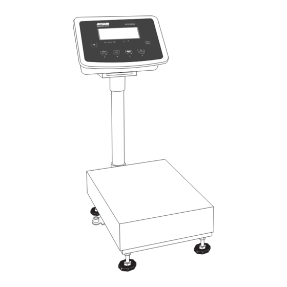
General View of the Equipment 1 Manufacturer’s ID tag 7 Level indicator (option) 2 Housing 8 Leveling feet 3 Power cable 9 Stainless steel weighing pan 4 Display and control unit retainer 10 Power plug 5 Display and control unit column 11 Cable gland cover (for optional RS-232 port outlet) 6 Column support foot 12 Load cell cable gland... -
Page 7: Setting Up The Scale
Setting Up the Scale Connecting Electronic Peripheral Devices § Make absolutely sure to unplug the scale from AC power or switch off (activate battery mode) before you connect or disconnect a peripheral device (printer or PC) to or from the interface port. Warm-up Time To deliver exact results, the scale must warm up for at least 30 minutes after initial connection to AC power. - Page 8 Leveling the Scale – Remove the load plate – Using the 4 foot screws, level the scale so that the air bubble is centered within the level indicator – Check to ensure that all leveling feet rest securely on the work surface –...
- Page 9 Assembly Procedure 1. Affix the column bracket with 4 screws 2. Install the column support leveling foot 3. Push the load-cell cable into the column 4. Insert the column into the bracket holder 5. Affix the column with 2 screws 6.
-
Page 10: Operating Design
Operating Design The scales in the Exceleron series consist of a weighing cell and a display and control unit. In addition to the choice of power supply or rechargeable mainte- nance free lead acid battery or dry battery, your scale also has an interface port for connecting peripheral devices, such as a printer, computer, etc. - Page 11 The maximum loading capacities of the scale in this series are listed in the table below, and depend on the position of the load on platform: Model Width Length Center* Side Comer (mm) (mm) ECL6 ECL15 ECL30 ECL60 ECL150 ECL300...
- Page 12 Power Management Option Scale connected to AC power: Scale running on battery power: On/Off Switch: On/Off Switch: On: Scale is operational & display shows function or mode On: Scale is operational and the display shows the function that is in use or mode that is in use Off: Depends on menu setting (“4.
-
Page 13: Descriptions Of The Keys
Descriptions of the Keys EXCELERON + / - Tare Gross Print Enter Gross Zero Tare Function 1) On/Off 2) Zero/Arrow-Left (ZERO/LEFT) “on/off” function will depend on different power supply Weighing mode: Set scale to zero condition. Needs setup menu for backlight control and for Parameter mode: Shift position of digit to the left auto power off. -
Page 14: Configuration (Setup Menu)
Configuration (Setup Menu) To configure the user interface of the scale to individual requirements Step Key (or instruction) Display 1. Switch off the scale (ON/OFF) 2. Switch on the scale (ON/OFF) 3. While all the segments are displayed: (ZERO/LEFT) > 2 sec Navigation in the Setup Menu Function (PRINT/ENTER) - Page 15 Setup Menu Serial COM Baud rate 1.1.1 1.1.2 1,200 1.1.3 2,400 1.1.4 4,800 1.1.5 9,600 1.1.6 19,200 Parity 1.2.1 7-bit-None 1.2.2 7-bit-None 1.2.3 7-bit-None 1.2.4 8-bit-None 1.2.5 8-bit-None 1.2.6 8-bit-None Print option 1.3.1 Short 1.3.2 Long/block 1.3.3 Continuous Backlight No options Auto Power Off 5 Min 10 Min...
-
Page 16: Application Programs
Application Programs Counting Step Key (or instruction) Display a. Select application program (Fn/UP) > 2 sec b. Select “Counting” (Fn/UP) or (G/N/DOWN) repeatedly c. Press PRINT/ENTER. (PRINT/ENTER) Display shows reference piece selection menu. Counting is blinking. d. Automatically the display will show (TARE/RIGHT) the reference pieces. -
Page 17: Check Weighing
Check Weighing Step Key (or instruction) Display a. Select application program (Fn/UP) > 2 sec b. Select “Checkweighing” (Fn/UP) or (G/N/DOWN) Repeatedly c. Press PRINT/ENTER to confirm. (PRINT/ENTER) d. Set lower limit; “LO” flashes. (Fn/UP) or (G/N/DOWN) and/or (ZERO/LEFT) or (TARE/RIGHT) e. -
Page 18: Toggling Between Weight Units
Toggling between Weight Units Step Key (or instruction) Display a. Select application program (Fn/UP) > 2 sec b. Select “Toggling Weight Units” (Fn/UP) or (G/N/DOWN) Repeatedly c. Select weight unit 1 (Fn/UP) or (G/N/DOWN) d. Confirm weight unit 1 (PRINT/ENTER) e. -
Page 19: Calibration/Span Adjustment
Calibration/Span Adjustment Calibrate the Scale Step Key (or instruction) Display a. Switch on the scale (ON/OFF) b. Zero the scale (ZERO/LEFT) c. Select calibration/linearization mode (TARE/RIGHT) > 2 Sec d. Select calibration (Fn/UP) or (G/N/DOWN) Repeatedly e. Confirm/start calibration. (PRINT/ENTER) After the zero point is stored, the required calibration weight is displayed f. - Page 20 Linearize the Scale Step Key (or instruction) Display a. Switch on the scale (ON/OFF) b. Zero the scale (ZERO/LEFT) c. Select calibration/linearization mode (TARE/RIGHT) > 2 sec d. Select linearization (Fn/UP) or (G/N/DOWN) repeatedly e. Confirm/start linearization (PRINT/ENTER) After the zero point is stored, the required linearization weight is displayed.
-
Page 21: Sbi Interface Protocol Descriptions
SBI Interface Protocol Description Output Format with 22 Characters The following data block format is output: W W W W W W W W W CR LF I : ID W : Weight value V : +/- sign U : Unit ID Codes S t a t Indicates a special weighing platform status, e.g., initialization, self-test, adjustment/calibration... -
Page 22: Data Input Formats
Special Error-dependent Codes: 10 11 12 13 14 15 16 17 18 19 20 21 22 n1 n2 CR LF n – n3 contains an error code of up to 3 digits. Data Input Formats You can enter certain commands to control weighing platform functions through the SBI interface. As with data output, data is input as 7-bit ASCII characters;... - Page 23 The CR and LF characters do not have to be transmitted in the data string. Control Commands ESC P CR LF Print, auto print: initiate / stop ESC T CR LF Zero/Tare – combination ESC V CR LF Zero the weighing platform ESC U CR LF Tare the weighing platform ESC S CR LF...
-
Page 24: Rs-232 Interface Diagram
RS-232 Interface Diagram DB 25 DB 9 Diagram for interfacing a computer or different peripheral device to the scale using RS-232 cable length up to 15 m. -
Page 25: Print Formats
Print Formats Printing Mode Options Printing out Options Printing out Options Mode of operation Mode of operation Short print Short print Block print (long print) Block print (long print) Continuous mode Continuous mode Normal weighing Net weight Gross weight (if tare is active) Gross weight (if tare is not active) mode Tare weight (if tare is active) - Page 26 b. Sample print outputs in different applications 2. Block printing mode: 2.1 Normal weighing 1. Short printing mode: Ex 1: If tare is zero 1.1 Normal weighing Ex 2: If tare is not zero 1.2 Counting 10 pcs W.Ref. 2.2 Counting mode 1.3 Checkweighing Ex 1: If tare is zero.
- Page 27 Ex 4: If the weight on the pan > upper limit set. 3. Continuous printing mode 3.1 Normal weighing Chk. Ex 1: If tare is not active Ex 2 : If tare value is present. Ex 5: If the weight on the pan is <10% of lower limit set, with a set tare value.
-
Page 28: Error Codes
Error Codes Error codes are shown on the main display. “Err“ codes are shown continuously; “Inf.“ messages are shown for 2 seconds, after which the program returns automatically to the weighing mode. Problem Cause Solution Nothing appears – No power available –... -
Page 29: Care & Maintenance
Care and Maintenance Cleaning Safe operation of the scale with the AC is no longer Unplug the scale from the AC power before cleaning. ensured when: To clean the weighing platform: use a piece of cloth, – There is visible damage to the AC adapter wet with a commercially available cleaning agent –... -
Page 30: Specifications
Specifications No of keys Display LCD, 6 digits, character height: 25 mm, 7 segment with backlight (amber) Functions 1. Zero, 2. Tare, 3. Counting, 4. Checkweighing, 5. Net/gross weight, 6. Toggle between weight units, 7. Auto power off (optional battery mode) Maximum readability 15000d Temperature range... -
Page 31: C Marking
Important Note: The operator shall be responsible for any modifications to Acculab equipment or connections of cables not supplied by Acculab and must check and, if necessary, correct these modifications. On request, Acculab will provide information on the minimum operating specifications (in accordance with the Standards listed above for defined immunity to interference). - Page 32 Acculab. The status of the information, specifications and illustrations in this manual is indicated by the date given below. Acculab reserves the right to make changes to the technology, features, specifications and design of the equipment without notice. Status: July 2008, Acculab W1A000 ·...
Need help?
Do you have a question about the ECL6 and is the answer not in the manual?
Questions and answers