Table of Contents
Advertisement
Advertisement
Table of Contents

Related Manuals for Zoom Cable Modem/Router


Summary of Contents for Zoom Cable Modem/Router
- Page 1 Cable Modem/Router with Wireless-N U S E R M A N U A L...
- Page 2 Do not place the cable modem in a confined space that may cause overheating. Do not restrict the flow of air around the cable modem. Zoom Telephonics assumes no liability for damage caused by any improper use of the cable modem. ...
-
Page 3: Table Of Contents
GETTING STARTED Package Contents............................5 System Requirements .............................5 INSTALLING THE CABLE MODEM/ROUTER WITH WIRELESS-N Before Installing Your Cable Modem/Router ....................7 If your cable service provider provided a cable modem starter kit ..............7 Hardware Connection...........................11 CONNECTING OTHER DEVICES TO THE CABLE MODEM/ROUTER Establishing your Wireless Network ....................14 Connecting a Windows 8 Computer with Built‐in Wireless Capabilities ............15 Connecting a Windows 7 Computer with Built‐in Wireless Capabilities........... 16 Connecting a Windows Vista Computer with Built‐in Wireless Capabilities ........16 Connecting a Windows XP Computer with Built‐in Wireless Capabilities......... 18 Connecting a Macintosh OS X Computer with Built‐in Wireless Capabilities........19 Connecting a Wireless‐enabled Device (including the iPhone or other cellular phones, iPad or other tablets, the iPod Touch, etc.) to the Cable Modem/Router............... 20 Connecting a Computer with a Wireless adapter to the Cable Modem/Router ....... - Page 4 ADVANCED MENU OPTIONS Options .................................54 IP Filtering ..............................57 MAC Filtering..............................58 Port Filtering..............................60 Forwarding..............................61 Port Triggers..............................63 DMZ Host..............................64 RIP Setup ..............................65 FIREWALL MENU OPTIONS Basic................................68 Event Log ..............................69 PARENTAL CONTROL MENU OPTIONS Basic................................75 User Setup ..............................78 ToD Filter (Time of Day Filter) ........................80 Event Log ..............................81 WIRELESS MENU OPTIONS Radio................................83 Primary Network ............................85 Guest Network..............................88 Advanced ..............................92 Access Control ..............................94 WMM (Wi‐Fi Multimedia) ..........................95 Bridging ................................97...
-
Page 5: Getting Started
If one is not available, you can use a wireless device to configure you modem. You may have already used the Quick Start flyer to set up your Cable Modem/Router, to establish an Internet connection, and perhaps to set up a local area network. If you did, you may not need to read this User Manual. - Page 6 Chapter 4: Changing your Wireless Settings. If you are using the Cable Modem/Router for online gaming and need to make changes to the router’s firewall, please see Chapter 5: Online Gaming. ...
-
Page 7: Installing The Cable Modem/Router With Wireless-N
You can call the cable company BEFORE installing your modem. You may also be asked for your cable modem's model name and number, which is ZOOM 5352. If you need the modem's serial number, you can find it near the CM-MAC address on the label. - Page 8 If you receive a kit like this, we recommend that you read the kit’s instructions and use them to install your Zoom Cable Modem/Router. This modem is a DOCSIS 3.0 cable modem/router certified by CableLabs, and connects like a normal cable modem.
- Page 9 3 Plug the power cube into the POWER connector on the rear panel of the cable modem and into an electrical outlet. Make sure the On/Off switch on the back of the cable modem is on. The Cable Modem/Router should go on with the Power LED lit up.
- Page 10 Network Name), wireless security enabled and a random Pre-Shared Key (Security Key/Password). These default settings for your modem/router are listed on the bottom label of your cable modem/router. Most users can simply use the default settings. You may want to change the wireless settings if you are...
-
Page 11: Hardware Connection
Cable Modem/Router. RF / Cable Connect your coaxial cable line to this port. POWER Connect the supplied power cube to this port. ON/OFF SWITCH Powers the Cable Modem/Router on or off. ... -
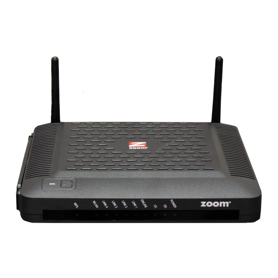
Page 12: Front Panel Leds
Front Panel LEDs Your Zoom cable modem has several lights on its front panel to help you monitor the Cable Modem/Router’s status. LIGHT COLOR DESCRIPTION BLINKING: WPS is in discovery mode (LED blinks for up to 2 minutes) ON: LED lit solid for 30 seconds after WPS... -
Page 13: Connecting Other Devices To The Cable Modem/Router
Modem/Router This chapter explains how to connect devices (computers, phones, tablets, game stations, etc.) to the Cable Modem/Router. These devices can be connected either wirelessly or to one of the Ethernet ports on your Cable Modem/Router. If you are connecting a computer or other device to an Ethernet LAN port of the Cable... -
Page 14: Establishing Your Wireless Network
WPS to set up your Wireless network if you want to use WPS for wireless connections to your cable modem/router. If some of the wireless devices do not support WPS, or if you do not know whether they do support WPS, you can configure each computer or device manually. To do that, select one of the possibilities for that computer or other device below: ... -
Page 15: Connecting A Windows 8 Computer With Built-In Wireless Capabilities
4 When prompted to enter your Network Security Key, enter your Pre-Shared Key (Security Key/Password) and hit Connect. Your Security Key/Password can be found on the bottom label of your Cable Modem/Router. 5 When asked “Do you want to turn on sharing between PCs and connect to devices on this network?”... -
Page 16: Connecting A Windows 7 Computer With Built-In Wireless Capabilities
2 In the Connect to a network dialog box, typically you then click Zoomxxxx where xxxx is 4 random alpha-numeric characters. Zoomxxxx is the SSID printed on the bottom label of your Cable Modem/Router. In the unlikely event that you changed the SSID from the default, select your new SSID. - Page 17 4 When prompted to enter your Network Security Key, enter your Pre-Shared Key (Security Key/Password) and hit Connect. Your Security Key/Password can be found on the bottom label of your Cable Modem/Router. 5 In the Successfully connected to [desired network] dialog box, you have three options.
-
Page 18: Connecting A Windows Xp Computer With Built-In Wireless Capabilities
4 When prompted to enter your Network Security Key, enter your Pre-Shared Key (Security Key/Password) and hit Connect. Your Security Key/Password can be found on the bottom label of your Cable Modem/Router. 5 Test your wireless connection. Open your computer’s Web browser and try to connect to a familiar Website. -
Page 19: Connecting A Macintosh Os X Computer With Built-In Wireless Capabilities
3 When prompted for the password in the next dialog box, enter your Pre-Shared Key (Security Key/Password) and hit Connect. Your Security Key/Password can be found on the bottom label of your Cable Modem/Router. 4 Test your wireless connection. Open your computer’s Web browser and try to connect to a familiar Website. -
Page 20: Connecting A Wireless-Enabled Device (Including The Iphone Or Other Cellular Phones, Ipad Or Other Tablets, The Ipod Touch, Etc.) To The Cable Modem/Router
Zoomxxxx where xxxx is 4 random alpha-numeric characters. Zoomxxxx is the SSID printed on the bottom label of your Cable Modem/Router. In the unlikely event that you changed the SSID from the default, select your new SSID. -
Page 21: Connecting A Computer With A Wireless Adapter To The Cable Modem/Router
Connecting a Computer with a Wireless adapter to the Cable Modem/Router 1 Go to the computer that is set up with a wireless adapter that you want to add to the network. For many wireless adapters, you will use their configuration manager software and click a Scan button or select a Site Scan, Scan Networks, or other similarly named tab to do a site search. -
Page 22: Using Wps As An Alternative Way To Set Up Your Wireless Network
If all the Wi-Fi compatible wireless devices on your network support WPS, you can choose to quickly setup your wireless network by pushing a button on your cable modem/router and on each wireless device connecting to your cable modem/router. Windows 8 and Windows 7 users should follow the instructions below: Other... -
Page 23: Connecting Additional Computers And/Or Other Devices To The Cable Modem/Router's Ethernet/Lan Ports
Follow the instructions below for each computer or other device. 1 If you connected the Cable Modem/Router to a computer using a wired connection when setting up the Cable Modem/Router, unplug the computer now if you don’t want that computer to stay connected to the Cable Modem/Router. - Page 24 4 If you are connecting a HomePlug adapter pair with one adapter plugged into the Cable Modem/Router and an AC outlet, and the other adapter plugged into a computer, game station, or other device and an AC outlet, make those connections and then go to step 5.
-
Page 25: Changing The Default Wireless Settings
Changing the Default Wireless Settings Your Cable Modem/Router comes from the factory with a default SSID (Wireless Network Name), WPA-PSK/WPA2-PSK wireless security and a random Wireless Security Key (Wireless Password). These default settings for your router are listed on the bottom label of your unit. -
Page 26: Changing Your Wireless Network Name(Ssid) And Pre-Shared Key
Disabling Security Changing your Wireless Network Name(SSID) and Pre-Shared 1 Open the Zoom Configuration Manager by typing the following in your Web browser's address bar: http://192.168.0.1 2 In the Login dialog box, type the following User Name and Password in lower case, then click Login. -
Page 27: Setting Up Security Using Wep
WEP can be configured two ways: 64-bit and 128-bit. 128-bit WEP provides more security than 64-bit. 1 Open the Zoom Configuration Manager by typing the following in your Web browser's address bar: http://192.168.0.1 2 In the Login dialog box, type the following User Name and Password in lower case, then click Login. -
Page 28: Disabling Security
Disabling Security If for some reason you need to set up an unsecured network, you will need to disable the default security that is currently set up for your Cable Modem/Router. Follow the instructions below. 1 Open the Zoom Configuration Manager by typing the following in your Web browser's address bar: http://192.168.0.1... -
Page 29: Online Gaming
Online Gaming Read this chapter if you are going to use your Cable Modem/Router for online gaming. Some online games require you to make changes to your firewall. This chapter explains the different ways you can modify the firewall to allow your online gaming system access. -
Page 30: Dmz Host
When assigning a static IP address to your gaming system you should select an address that is outside the IP addresses assigned by the Cable Modem/Router’s DHCP server. By default the DHCP Server assigns addresses from 192.168.0.10 to 192.168.0.255. -
Page 31: Port Triggers
Then click the DMZ Host submenu. The DMZ Host page appears: Enter the last byte of the LAN IP address of the static IP address you assigned to your gaming system. For example if you assigned 192.168.0.5 enter 5. Click Apply. Your gaming system should now work with all your online games. - Page 32 Both the username and password are case sensitive. The default username and password are printed on the bottom label of your unit. Click the Login button to access the Cable Modem/Router. The Status page appears. Click Advanced in the menu bar.
- Page 33 Select TCP in the Protocol drop down menu since these ports use TCP. Enter a name for this rule, for example WOW1. Click Enable then click Apply. Your new rule will appear in the table. Repeat steps 7-9 for the next rule. In this case only one port is used, 3724. Enter 3724 in the Trigger Start/End Port and Target Start/End Port fields.
-
Page 34: Advanced Settings
Advanced Setup is primarily for technically advanced users. For most people, the options that are set by default when the Cable Modem/Router is installed are sufficient. However, those who want or need to change the default settings can do so using the advanced setup pages in the Zoom Configuration Manager. -
Page 35: Accessing The Zoom Configuration Manager
Cable Modem/Router and its ports. To access the Zoom Configuration Manager, use the following procedure: Launch a Web browser. Note: Your computer does not have to be online to configure your Cable Modem/Router. -
Page 36: Understanding The Configuration Manager Interface Screens
Both the username and password are case sensitive. The default username and password are printed on the bottom label of your unit. After you log in to the Zoom Configuration Manager interface, you can change the default password on the Status - Security page. -
Page 37: Configuration Manager Interface Menus
You can skip to specific sections of this User Manual based on your intended use of the Cable Modem/Router with Wireless-N. Each of the menu options in your Configuration Manager is covered as a separate chapter in the remaining portion of the User Manual. - Page 38 Table 1. Configuration Manager Interface Menus Chapter Menu Go to this section if Options Page you want to… monitor or troubleshoot problems with the Cable Status Modem/Router make some Basic modifications for more advanced uses make use of advanced router features Advanced supported by the Cable Modem/Router...
-
Page 39: Status Menu Options
Use diagnostic tools for troubleshooting Software The Software page is a read-only screen that shows the Cable Modem/Router’s current system software version. This page appears when you first log in to the Configuration Manager interface. You can also display it by clicking Status in the menu bar and then click the Software submenu. -
Page 40: Connection
Connection The Connection page is a read-only screen that shows the status of steps in your Cable Modem/Router registration process. It also shows your Cable Modem/Router’s upstream and downstream channel status. To access the Connection page, click Status in the menu bar and then click the Connection submenu. -
Page 41: Security
Figure 5. Example of Connection Page Security The Security page allows you to configure access privileges and restore the Cable Modem/Router to its factory defaults and allows you to disable routing and use the Cable Modem/Router as a pure bridge modem. To access the Security page, click Status in the menu bar and then click the Security submenu. - Page 42 In the Security submenu, select the Yes button next to Restore Factory Defaults. Click Apply. Click OK to reboot the Cable Modem/Router. The reboot is complete when the POWER LED stops blinking. If the Login screen doesn’t reappear, click the Refresh link to log back in to the Configuration Manager.
-
Page 43: Diagnostics
The Diagnostics page allows you to troubleshoot connectivity problems. Two utilities are provided for troubleshooting network connectivity: Ping and Traceroute. Ping allows you to check connectivity between the Cable Modem/Router and devices on the LAN while Traceroute allows you to map the network path from the Cable Modem/Router to a public host. - Page 44 Table 4 describes the items you can select. Figure 7. Example of Diagnostics - Ping Page ...
- Page 45 Figure 8. Example of Diagnostics - Traceroute Page To run either utility: Select the utility from the Utility drop-down list. Make any changes to the default parameters. Select Start Test to begin. The window will automatically be refreshed as the results are displayed in the Results table.
- Page 46 Table 4. Diagnostics Menu Option Option Description Utility Select the utility for troubleshooting. Parameters Enter the required parameters to perform diagnostics. Click this button to begin diagnostic after making any changes to the Start Test default parameters. Abort Test Click this button to abort Ping diagnostics. Clear Results Click this button to clear the results table.
-
Page 47: Basic Menu Options
Backup and restore of configuration settings Setup The Setup page allows you to configure the basic features of the Cable Modem/Router related to your ISP’s connection. To access the Setup page, click Basic in the menu bar and then click the Setup submenu. - Page 48 Set the base LAN IP for your private network. By default this is LAN IP Address 192.168.0.1 There is normally no need to change this. Select how your Cable Modem/Router obtains an IP address. The options are via DHCP or manual configuration of a static IP address. Connection...
-
Page 49: Dhcp
Cable Modem/Router’s DHCP server by selecting the No radio button. If you do this, make sure the IP address assigned to the Cable Modem/Router is on the same subnet as that of the external DHCP server, or you won’t be able to access the Cable Modem/Router from the LAN. -
Page 50: Ddns
Caution: Some service providers may consider connection of such a server to be a breach of your service agreement. The Cable Modem/Router supports a dynamic DNS client compatible with the Dynamic DNS service (http://www.dyndns.com/). You must sign up with this service if you want to use it. - Page 51 DNS domain to which your host will be assigned. You will also be asked for your host’s current IP address. This is the WAN IP address that has been assigned to your Cable Modem/Router during provisioning. (See WAN IP Address on the Basic / Setup web page.) Enter your account information on the Basic / DDNS web page, enable the service by selecting www.DynDNS.org from the DDNS Service drop-down list, and click Apply.
-
Page 52: Backup
Backup Note: Some software versions may not support this feature. The Backup page allows you to save the current Cable Modem/Router configuration settings to a local PC. You can then later restore these settings if you need restore a particular configuration, or to recover from changes you may have made that have had an undesirable effect. - Page 53 Figure 12. Example of Backup Page ...
-
Page 54: Advanced Menu Options
Configure DMZ hosting Configure RIP parameters Options The Options page allows you to configure the Cable Modem/Router to operate in different modes that adjust how the device routes IP traffic. To access the Options page: Click Advanced in the menu bar. - Page 55 Figure 13. Example of Options Page ...
- Page 56 Option Description Prevents the Cable Modem/Router or the PCs from responding to pings to the Cable Modem/Router’s WAN IP address or to the WAN Blocking devices behind it. This makes it more difficult for hackers to attack your PCs and other devices on your network.
-
Page 57: Ip Filtering
We recommend assigning a static IP address to your computer when using IP Filtering. By default, the Cable Modem/Router uses DHCP to assign IP addresses. DHCP does not guarantee that your computer will be assigned the same IP address. When assigning a static IP address to your computer you should select an address that is outside the IP addresses assigned by the Cable Modem/Router’s DHCP server. -
Page 58: Mac Filtering
Description Enter the last byte of the IP address. The upper bytes of the IP Start/End address are set automatically from the Cable Modem/Router IP Address address. To activate the IP address filter, you must also check the Enable box Enable and click Apply. - Page 59 Figure 15. Example of MAC Filtering Page Table 10. MAC Filtering Menu Option Option Description PCs and other devices can be added to the MAC filter table by entering their MAC addresses into the Add MAC Address box, and clicking the Add MAC Address button. Internet traffic to and from each listed Address will be blocked.
-
Page 60: Port Filtering
Port Filtering The Port Filtering page allows you to configure port filters in order to block Internet traffic to specific ports on all devices on your LAN. Similarly, you can prevent PCs from sending outgoing TCP/UDP traffic to the Internet from specific IP port numbers. -
Page 61: Forwarding
For example, if you would like to block all PCs on the private LAN from accessing HTTP sites (or “web surfing”): Set the Start Port to 80, the End Port to 80. Set the protocol to TCP. Check the Enable box to the right of the entry to store settings. Click Apply button to activate the filter rules. - Page 62 Figure 17. Example of Forwarding Page To activate the port forwarding: Enter the port range of the Internet traffic that you want to forward, and the IP address of the server to which you want to forward that traffic. Select the protocol(s) to be forwarded. Check the Enable box to the right of the entry to store settings.
-
Page 63: Port Triggers
Port Triggers are similar to Port Forwarding except that they are not static ports held open all the time. With the port triggering function, the Cable Modem/Router detects outgoing data on a specific IP port number and opens corresponding target ports for incoming data. -
Page 64: Dmz Host
Select the forwarding protocol(s). Enter a name for your port triggering rule. Check the Enable box to the right of the entry to store settings. Click the Apply button to activate the forwarding rules. Table 13. Port Triggers Menu Option Option Description Trigger Range... -
Page 65: Rip Setup
RIP is a protocol that requires negotiation from both sides of the network (e.g. both the Cable Modem/Router and your service provider’s CMTS (Cable Modem Termination System)). Your service provider will normally set this up based on their knowledge of... - Page 66 Figure 20 shows an example of the menu and Table 14 describes the items you can select. Figure 20. Example of RIP Setup Page Note: RIP messages will only be sent when the Cable Modem/Router is configured for Static IP Addressing (see the Basic – Setup page).
- Page 67 To specify a RIP unicast destination IP address, enter the IP address and subnet mask. Table 14. RIP Setup Menu Option Option Description Check this box to enable RIP authentication for RIP Authentication routing protocols RIP Authentication Key Enter the set of keys for your interface. Enter the ID to identify the key used to create the RIP Authentication Key ID authentication data.
-
Page 68: Firewall Menu Options
Firewall Menu Options The Firewall Menu lets you: Configure the level of protection your firewall provides View the firewall logs Basic The Basic page allows you to configure the level of protection your firewall offers and also what type of attacks it should detect.. To access the Basic page: Click Firewall in the menu bar. -
Page 69: Event Log
Permitted connections, blocked connections, known Internet attack types, and Cable Modem/Router configuration events can also be logged. The SysLog server must be on the same subnet as the Private LAN behind the Cable Modem/Router (typically 192.168.0.x). To access the Event Log page: Click Firewall in the menu bar. - Page 70 Figure 22. Example of Event Log Page Table 16. Local Log Menu Option Option Description Permitted Enabling this feature causes the Cable Modem/Router to report all Connections permitted connection attempts. Blocked Enabling this feature causes the Cable Modem/Router to report all Connections blocked connection attempts.
- Page 71 SMTP Enter the username of the email account you will send from. Username SMTP Enter the password of the email account you will send from. Password Check to enable sending alert email, when an attack is detected. E-mail Alerts Below is a complete list of the capable SysLog server attack/notification types and their format.
- Page 72 YYYY The four-digit year. The IP address of Cable Modem/Router sending the SysLog event. HostIP This is the LAN IP Address on the Basic - Setup page. Can be one of the following: “TCP”, “UDP”, “ICMP”, “IGMP” or “OTHER”.
- Page 73 The table below lists all events that can be sent to the SysLog server. Table 18. SysLog Server Event and Meaning Event Text Meaning An inbound request was made, and accepted, from a ALLOW: Inbound access public network client to use a service hosted on the firewall request or a client behind the firewall.
- Page 74 management enabled specified port # on the public interface) has been enabled [port#] via the user interface. Remote config Remote configuration management has been disabled via management disabled the user interface. The system established the current system time via the Time Of Day established DOCSIS cable modem registration process.
-
Page 75: Parental Control Menu Options
Parental Control Menu Options The Parental Control Menu lets you: Configure the rules for Internet access based on user or time period Configure the rules to block certain Internet contents and certain web sites View the event logs related to parental control To set up Parental Control, you first set up Policies in the Basic Setup Menu. - Page 76 Figure 23. Example of Basic Page ...
- Page 77 Table 19. Basic Setup Menu Option Option Description Enable Parental Check the box to enable Parental Control. Control Content Policy Enter a name for a content policy, and click Add New Policy. Configuration Enter a keyword in the field at the bottom of the keyword list, and click Add Keyword.
-
Page 78: User Setup
User Setup The User Setup page is the master page to which each individual “user” is linked to a specified time access rule, content filtering rule, and login password. To access the User Setup page: Click Parental Control in the menu bar. Then click the User Setup submenu. - Page 79 Table 20. User Setup Menu Option Option Description User Enter a user name (e.g. Mom, Dad, Bro, Sis) and click Add User. Configuration Select a user from the drop-down list. Click the checkbox to enable Users Settings parental control for this user. Password Enter the password for this user.
-
Page 80: Tod Filter (Time Of Day Filter)
ToD Filter (Time of Day Filter) The ToD page allows you to configure the Internet access policies according the time of day settings. This page is tied to the Parental Control - User Setup page. You can define up to 30 time access policies. You can define policies that block all public Internet traffic for entire days or for specific time periods within each day. -
Page 81: Event Log
Table 21. ToD Filter Menu Option Option Description Time Access Policy Enter a name for the time access policy and click Configuration Add New Policy. Select a policy from the drop-down list. Click the Time Access Policy List Enable checkbox to enable this rule. Click the checkboxes of the days that this rule Days to Block applies to. - Page 82 If the online lookup service detects that the URL falls in a category that is blocked. To access the Event Log page: Click Parental Control in the menu bar. Then click the Event Log submenu. Figure 26 shows an example of the menu. Figure 26.
-
Page 83: Wireless Menu Options
Wireless Menu Options The Wireless Menu lets you: Configure Cable Modem/Router to serve as a wireless access point (AP) Configure essential and advanced settings of wireless network Configure guest network for temporary visitors Configure WMM QoS Note: Your Cable Modem/Router has been preconfigured to support wireless connections without any further configuration. - Page 84 802.11n-mode adjust to avoid interference with neighboring devices. Specify radio frequency bandwidth, either 20MHz single, or 40MHz (dual channel), that the Cable Modem/Router will use if Bandwidth 802.11n mode is configured as Automatic and the Control Channel is configured as Automatic.
-
Page 85: Primary Network
Table 23. Country Extension Channel List Control Channel Sideband for Extension Control Channel Channel US Channel 1-7 Lower Channel Number + 4 US Channel 5-11 Upper Channel Number - 4 Example 1: If your control channel is set to 1, the extension channel will be transmitted on channel 5. - Page 86 Figure 28. Example of Primary Network Page Table 24. Primary Network Menu Option Option Description Select Enable to enable primary wireless network. Primary Network Set the Network Name (also known as SSID) of the Network Name (SSID) wireless network. This is a 1-32 ASCII character string. Closed Network Select Enable to suppress broadcast of the SSID.
- Page 87 Set to zero RADIUS server is enabled) to disable periodic rekeying. Interval (in seconds) at which the Cable Modem/Router (if using WPA-PSK key management) or RADIUS server (if WPA/WPA2 Re-auth using WPA key management) sends a new group key out Interval to all clients.
-
Page 88: Guest Network
(intranet) Web sites or files. Traditionally, you needed to use different APs to configure different Basic Service Sets (BSSs). Your Cable Modem/Router supports Multiple SSIDs which allows you to use the same access point to provide several BSSs simultaneously. You can then assign various privileges to different SSIDs and associated networks. - Page 89 Figure 29. Example of Guest Network Page ...
-
Page 90: Guest Network Menu Option
(Relevant only when the key-management capable clients periodically. Set to zero RADIUS server is enabled) to disable periodic rekeying. Interval (in seconds) at which the Cable Modem/Router (if WPA/WPA2 Re-auth using WPA-PSK key management) or RADIUS server (if Interval using WPA key management) sends a new group key out... - Page 91 to all clients. The re-keying process is the WPA equivalent of automatically changing the WEP key for an AP and all stations in a WLAN on a periodic basis. WEP Encryption can be set to WEP 128-bit, 64-bit, or WEP Encryption Disable.
-
Page 92: Advanced
Advanced The Advanced page allows you to configure advanced wireless settings. Most users will have no need to change these settings. To access the Advanced page: Click Wireless in the menu bar. Then click the Advanced submenu. Figure 30 shows an example of the menu and Table 26 describes the items you can select. -
Page 93: Advanced Menu Option
Table 26. Advanced Menu Option Option Description Mode Auto by default. When Xpress is turned on, aggregate throughput can XPress Technology improve significantly. The 802.11g standards provide a protection method so 802.11g and 802.11b devices can co-exist in the same network without “speaking”... -
Page 94: Access Control
This value specifies the maximum size for a packet before data is fragmented into multiple packets. If you experience a high packet error rate, you may slightly increase the fragmentation threshold. Setting the fragmentation Fragmentation Threshold threshold too low may result in poor network performance. Only minor reduction of the default value is recommended. -
Page 95: Wmm (Wi-Fi Multimedia)
If you enable the WMM feature, you may need to decide whether or not to broadcast Cable Modem/Router’s network name. Broadcasting allows you to easily recognize your wireless network in the list of available networks. Once you have configured your wireless clients, it is recommended that you disable the broadcasting feature. - Page 96 Figure 32. Example of WMM Page ...
-
Page 97: Bridging
WMM Support frame. No-Acknowledgement Select On to not transmit acknowledgments for data. Select On to allow the AP (Cable Modem/Router) queuing packets for stations/clients in power-save mode. Queued Power Save Support packets are transmitted when the station/client notifies AP that it has left power-save mode. - Page 98 Up to 4 remote bridges may be connected. Remote Bridges Typically, you will also have to enter your AP’s MAC address on the remote bridge. The Cable Modem/Router’s wireless MAC address can be found on the Wireless Interfaces page. ...
-
Page 99: Vpn (Virtual Private Network) Menu Options
VPN (Virtual Private Network) Menu Options The VPN Menu lets you: Configure a VPN tunnel View VPN event logs Basic Setting This page allows you to enable VPN protocols and manage VPN tunnels. A virtual private network (VPN) is a computer network in which some of the links between nodes are carried by open connections or virtual circuits within some larger network (e.g., the Internet) as opposed to by physical wires, as in a traditional private network. -
Page 100: Ipsec
The IPSec page allows you to configure IPSec tunnel and endpoint settings. A VPN tunnel is usually established in two phases. Each phase establishes a security association (SA), a contract indicating what security parameters Cable Modem/Router and the remote IPSec Cable Modem/Router will use. - Page 101 The ESP and AH protocols are necessary to create a Security Association (SA), the foundation of an IPSec VPN. An SA is built from the authentication provided by the AH and ESP protocols. The primary function of key management is to establish and maintain the SA between systems.
- Page 102 Figure 35. Example of IPSec Page ...
- Page 103 Enter the subnet scale for address group. Subnet Enter the subnet mask for address group. Mask Select the type to identify the Cable Modem/Router. The Identity Type choices are:WAN IP address, LAN IP address, FQDN (Fully Qualified Domain Name) or Email address.
- Page 104 DES: a 56-bit key with the DES encryption algorithm 3DES: a 168-bit key with the DES encryption algorithm. Both the Cable Modem/Router and the remote IPSec router must use the same algorithms and key, which can be used to encrypt and...
- Page 105 DES: a 56-bit key with the DES encryption algorithm 3DES: a 168-bit key with the DES encryption algorithm. Both the Cable Modem/Router and the remote IPSec router must use the same algorithms and key , which can be used to encrypt and...
-
Page 106: L2Tp/Pptp
Select Enable to force the Cable Modem/Router to periodically Dead Peer Detection detect if the remote IPSec Cable Modem/Router is available or not. Manual Encryption If Manual mode is selected in the Key Management field, enter a 16 hexadecimal digits manual encryption key for encryption. - Page 107 Figure 36. Example of L2TP/PPTP Page ...
-
Page 108: Event Log
Table 32. L2TP/PPTP Menu Option Option Description Configure the dedicated IP address pool for L2TP/PPTP. The LAN IP subnet at one end of the VPN tunnel must be different from the LAN PPP Address Range IP subnet at the other end of the VPN tunnel. For example, if (Start/End) one side’s LAN subnet is 192.168.0.x, then the other side should be 192.168.1.x (where the subnet mask in this... - Page 109 Figure 37. Example of Event Log Page Table 33. Event Log Menu Option Option Description Time Shows the local time mapping to a certain log event. Description Shows detailed information of a VPN event log. ...
-
Page 110: Appendix A: Troubleshooting Tips
I cannot access my Internet service or send or receive email. Solution The following front panel lights on the Cable Modem/Router – ONLINE, US (upstream), DS (downstream), and POWER – must be solidly lit before your modem will let you connect to the Internet. - Page 111 When your provider asks for your MAC address tell them the CM MAC address on your Cable Modem/Router’s bottom label. Restart your computer or other devices connected to the Cable Modem/Router. This ensures that they receive a correct IP address from the router. ...
- Page 112 If changing the wireless channel did not help you should reduce the amount of bandwidth your wireless connection is using from 40 Mhz to 20 Mhz. To do that, follow these steps: Open the Zoom Configuration Manager by entering the following in your Web browser's address bar: http://192.168.0.1 In the Login dialog box, type the following User Name and Password in lower case, then click Login.
-
Page 113: Appendix B: If You Need Help
Appendix B: If You Need Help We encourage you to register your product and to notice the many support options available from Zoom. Please go to www.zoomtel.com/techsupport. From here you can register your router and/or contact our technical support experts and/or use our intelligent database SmartFacts and/or get warranty information. -
Page 114: Appendix C: Compliance
Appendix C: Compliance FCC Interference Statement This equipment has been tested and found to comply with the limits for a Class B digital device pursuant to Part 15 of the FCC Rules. These limits are designed to provide reasonable protection against radio interference in a commercial environment. This equipment can generate, use and radiate radio frequency energy and, if not installed and used in accordance with the instructions in this manual, may cause harmful interference to radio communications. - Page 115 IMPORTANT NOTE: FCC Radiation Exposure Statement This equipment complies with FCC radiation exposure limits set forth for an uncontrolled environment. This equipment should be installed and operated with minimum distance 20cm between the radiator & your body. This transmitter must not be co-located or operating in conjunction with any other antenna or transmitter.
Need help?
Do you have a question about the Cable Modem/Router and is the answer not in the manual?
Questions and answers