
Related Manuals for Fujitsu Siemens Computers PRIMERGY TX200 S3


Summary of Contents for Fujitsu Siemens Computers PRIMERGY TX200 S3
- Page 1 PRIMERGY Susanne Däschlein Fujitsu Siemens Computers GmbH München 81730 München e-mail: email: manuals@fujitsu-siemens.com Tel.: (089) 61001155 Fax: (++49) 700 / 372 00000 TX200 S3 Sprachen: En...
-
Page 2: Copyright And Trademarks
Gesellschaft für Technik-Dokumentation mbH www.cognitas.de Copyright and Trademarks Copyright © 2006 Fujitsu Siemens Computers GmbH. All rights reserved. Delivery subject to availability; right of technical modifications reserved. All hardware and software names used are trademarks of their respective manufacturers. -
Page 3: Table Of Contents
Contents Introduction ......5 Overview of the documentation ....5 Extensions and conversions . - Page 4 Contents Conversion standard PS to hot-plug PS ... Converting from the floorstand model to the rack model . . Completion ......14.1 Floorstand model .
-
Page 5: Introduction
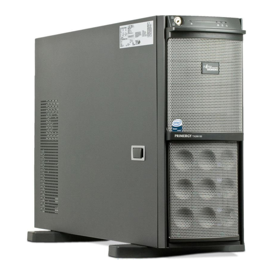
Introduction The PRIMERGY TX200 S3 Server is an Intel-based server for medium-sized and large networks. The server is suitable for use as a file server as well as an application, information, or Internet server. It is available as a floorstand or rack model. - Page 6 Overview of the documentation Introduction – The Operating Manual for PRIMERGY TX200 S3 (PDF available on the ServerBooks CD supplied) – The Technical Manual for the system board D2109 (PDF available on the ServerBooks CD supplied) – The “BIOS Setup” manual (PDF available on the ServerBooks CD supplied) –...
-
Page 7: Extensions And Conversions
Introduction Extensions and conversions Extensions and conversions Second processor The system board can be upgraded with a second processor. Only processors of the same type may be used on the system board. The second processor must have at least the same clock frequency as the first processor. Extension of the main memory Six slots (2 slots form a memory bank) are provided for the main memory. - Page 8 Extensions and conversions Introduction RemoteView RemoteView provides you with a comprehensive test and diagnostics package. The relevant hardware components are integrated on the system board. SATA Software RAID (scheduled autum 2006) The SATA SW RAID 5 functionality will be activated by installing a license key (RAID key).
-
Page 9: Notational Conventions
Introduction Notational conventions Notational conventions The following notational conventions are used in this manual: Text in italics indicates commands, menu items or software programs. „Quotation marks“ indicate names of chapters and terms that are being emphasized. Ê describes activities that must be performed in the order shown. -
Page 11: Procedure
Procedure CAUTION! The actions described in these instructions should only be performed by technical specialists. Equipment repairs should only be performed by authorized, qualified staff. Any unauthorized opening and improper repairs could expose the user to risks (electric shock, energy hazards, fire hazards) and could also damage the equipment. -
Page 13: Safety Notes
Safety notes The following safety notes are also provided in the “Safety notes and other important information” manual. This device complies with the relevant safety regulations for data processing equipment. If you have any questions about where you can set up the device, contact your sales outlet or our customer service team. - Page 14 Safety notes Installation and operation CAUTION! If the rack model is integrated in an installation that receives power from an industrial (public) power supply network with the IEC309 connector, the (public) power supply protection must comply with the requirements for the non-industrial (public) power supply networks for the type A connector.
- Page 15 Safety notes CAUTION! Make sure that no objects (such as bracelets or paper clips) fall into or liquids spill into the device (risk of electric shock or short circuit). In emergencies (e.g. damaged casing, controls or cables, penetration of liquids or foreign matter), switch off the device immediately, remove the power plug and contact your sales outlet or customer service team.
- Page 16 Safety notes Batteries CAUTION! Incorrect replacement of batteries may lead to a risk of explosion. The batteries may only be replaced with identical batteries or with a type recommended by the manufacturer (see the technical manual for the system board under “Related publications”...
- Page 17 Safety notes Note about the laser The CD-/DVD-ROM drive is classified for laser class 1according to IEC 60825- CAUTION! The CD-/DVD-ROM drive contains a laser diode (LED). Sometimes the LED produces a stronger laser beam than laser class 1. Direct view into this laser beam is dangerous.
- Page 18 Safety notes Place all components on a static-safe base. You will find a detailed description for handling ESD components in the relevant European or international standards (DIN EN 61340-5-1, ANSI/ESD S20.20). Options Guide TX200 S3...
-
Page 19: Preparation
Preparation CAUTION! Observe the safety instructions in the chapter “Safety notes” on page 13ff. Floorstand model 4.1.1 Opening the server Ê Terminate all applications and shut down the server correctly. Ê If your operating system has not switched off the sever, press the on/off switch. -
Page 20: Removing The Front Cover
Floorstand model Preparation 4.1.2 Removing the front cover Remove the front cover when making the following extensions and upgrades: – Installing/removing accessible drives – Upgrading the floorstand model to a rack model Figure 3: Removing the hard disk cover Ê Open the server and remove the key. Ê... - Page 21 Preparation Floorstand model Figure 4: Pulling out the locking buttons Ê Pull out the two green locking buttons (1+2). Figure 5: Removing the front cover Ê Pull the front cover forward slightly at the lower edge (1). Ê Unhook the front cover at the top (2) and remove it. Options Guide TX200 S3...
-
Page 22: Rack Model
Rack model Preparation Rack model Ê Terminate all applications and shut down the server correctly. Ê If your operating system has not switched off the server, press the on/off button. Ê Pull all power connectors out of the power outlets. 4.2.1 Opening the server Figure 6: Loosening the knurled screws... - Page 23 Preparation Rack model Depending on how accessible the server is in the rack cabinet, it can make sense to remove it from the cabinet. If you do not want to remove the server from the rack cabinet, please skip this page. If the server is integrated in a Classic rack cabinet, instructions on how to remove it are provided in the Operating Manual.
- Page 24 Rack model Preparation Figure 8: Opening the latch Ê Open the latch. Figure 9: Removing the top cover Ê Push back the top cover approxiate 2 cm (1). Ê Remove the top cover (2). Options Guide TX200 S3...
-
Page 25: Removing The Rack Front Cover
Preparation Rack model 4.2.2 Removing the rack front cover Remove the rack front cover when carrying out the following extension: – Installing/removing accessible drives Figure 10: Removing the rack front cover Ê Remove two screws on either side (1). Ê Remove the rack front cover to the front together with the plastic cover (2). Options Guide TX200 S3... -
Page 27: Main Memory
FBD533/PC2-4200F or FDB667/PC2-5300 fully buffered DIMM modules and must be populated in pairs. It is only allowed you use memory modules released by Fujitsu Siemens Computers. – Each pair must consist of identical memory modules (2 way interleaved mode). -
Page 28: Extending/Replacing The Main Memory
Extending/replacing the main memory Main memory – The module capacity between pairs can differ: pair 1A/1B can be populated with two 512 Mbyte modules and pair 2A/2B with two 1 Gbyte modules. The table below shows the order in which the memory banks must be equipped: module pair 1A/1B module pair 2A/2B module pair 3A/3B... - Page 29 Main memory Extending/replacing the main memory Figure 13: Removing a memory module Ê Press the holders on either side of the mounting location concerned outward (1). Ê If the mounting location was already equipped: pull the memory module out of the mounting location (2). Figure 14: Inserting a memory module Ê...
- Page 30 Extending/replacing the main memory Main memory Figure 15: Inserting the ventilation duct over the main memory Ê Reinsert the ventilation duct over the main memory. CAUTION! Take note of the guides in the chassis (see arrows). Ensure that the latch (1) engages. Ê...
-
Page 31: Processors
Processors CAUTION! Observe the safety instructions in the chapter “Safety notes” on page 13ff. CAUTION! Processors are modules which can react extremely sensitively to electro- static discharges and which must therefore always be handled with care. After a processor has been removed from its protective sleeve or from its socket, place it with its smooth side down on a non-conducting, antistatic surface. - Page 32 Installing a second processor Processors Server with standard fans Ê Remove the heat sink holder (see figure 18 on page 33): Ê Press the green touch point in the direction of the arrow. Ê Lift out the heat sink holder. Ê...
- Page 33 Processors Installing a second processor Server with option redundant fans Figure 17: Removing the ventilation duct over the system fans Ê Lift out the ventilation duct over the system fans. Figure 18: Removing the heat sink holder Ê Press the green touch point in the direction of the arrow. Options Guide TX200 S3...
- Page 34 Installing a second processor Processors Ê Lift out the heat sink holder. Figure 19: Removing the dummy cover for the processor fan Ê Press on the dummy cover for the processor fan in the direction of the arrow, unhook it (see circles) and remove the dummy cover downward. CAUTION! Keep the dummy cover for future use.
- Page 35 Processors Installing a second processor Figure 20: Removing the processor fan holder Ê Press the two green touch points simultaneously in opposite directions (see arrows) and lift out the processor fan holder. Installing the processor and the heat sink Figure 21: Releasing the lever Ê...
- Page 36 Installing a second processor Processors Figure 22: Inserting the processor Ê Position the new processor over the socket and then carefully press it into the socket (1). CAUTION! The processor can only be installed in one particular direction. Note the marking on one of the corners. To avoid damaging the pins or the processor, do not force it into the socket.
- Page 37 Processors Installing a second processor Figure 23: Removing the protective cover Ê Remove the protective cover on the underside of the heat sink. Options Guide TX200 S3...
- Page 38 Installing a second processor Processors Figure 24: Installing the heat sink Ê Place the heat sink on the processor socket. CAUTION! If you find an air flow arrow on the top side of the heat sink, place the heat sink in the way that the air flow arrow shows in direction of the server’s rear side.
- Page 39 Processors Installing a second processor Server with standard fans Figure 25: Installing the standard fans Ê Reinstall the standard fans. CAUTION! Ensure that the two green touch points engage. Ê Reinstall the heat sink holder (see figure 27 on page 40).
- Page 40 Installing a second processor Processors Server with option redundant fans Figure 26: Installing the processor fan holder Ê Reinstall the processor fan holder. CAUTION! Ensure that the two green touch points engage. Figure 27: Installing the heat sink holder Ê Reinstall the heat sink holder. CAUTION! Ensure that the green touch point engages.
- Page 41 Processors Installing a second processor Figure 28: Installing the ventilation duct over the system fans Ê Reinstall the ventilation duct over the system fans. CAUTION! Pay attention to the guides on the processor fan holder and the housing (see arrows). Ensure that no damage is caused to the cables.
-
Page 42: Replacing The Processor
Replacing the processor Processors Replacing the processor CAUTION! Only processors of the same type may be used on the system board. The second processor must have at least the same clock frequency as the first processor. The server always configures itself to the lower clock frequency of the two processors. - Page 43 Processors Replacing the processor Figure 29: Removing the heat sink Ê Loosen the four screws in a crossover pattern. Ê Loosen the heat sink by turning it back and forth and then lift it out. Ê Remove the residual thermal paste from the underside of the heat sink. Ê...
- Page 44 Replacing the processor Processors Figure 30: Removing an old processor Ê Release the socket lifter by pressing it sideways and pull it upward as far as it will go (1). Ê Open the cover (2). Ê Lift the installed processor carefully out of the socket (3). Figure 31: Inserting a new processor Ê...
-
Page 45: Replacing The Heat Sink
Processors Replacing the heat sink Ê Apply a small amount of thermal paste to the upper side of the new processor. Ê Ensure a thin and even distribution of the thermal paste. Ê Place the heat sink on the processor socket (see page 38). - Page 46 Replacing the heat sink Processors Ê Standard fans: Reinstall the standard fans (see page 39). Ê Redundant fans: Reinstall the processor fan holder (see page 40). Ê Reinstall the heat sink holder (see page 40). Ê Redundant fans: Reinstall the ventilation duct over the system fans (see page 41).
-
Page 47: Accessible Drives
Accessible drives CAUTION! Observe the safety instructions in the chapter “Safety notes” on page 13ff. Three free 5.25-inch bays are available for accessible drives. The lowest 5.25-inch bay can be used to install a multibay with a 3.5-inch x 1- inch floppy disk drive. - Page 48 Installing a slim line CD/DVD-ROM drive Accessible drives Figure 33: Installing the CD-DVD-ROM drive in the mounting frame Ê Install the slim line CD/DVD-ROM drive in the provided mounting frame. No screws are needed. The mounting frame has little noses which fit into the CD/DVD-ROM drive.
- Page 49 Accessible drives Installing a slim line CD/DVD-ROM drive Figure 35: Connecting the data cable on the system board Ê Connect the data cable to the system board. You will find the connector near to the connector of the floppy cable. Ê...
-
Page 50: Installing An Accessible 5.25-Inch Drive
Installing an accessible 5.25-inch drive Accessible drives Installing an accessible 5.25-inch drive The 5.25-inch drives available are magnetic tape drives and DVD-ROM burners. These drives can be installed in the free 5.25-inch bays. Ê Open the server and remove the front cover or rack front cover as described in the chapter “Preparation”... - Page 51 Accessible drives Installing an accessible 5.25-inch drive M3 screw (small screw head) UNC screw (large screw head) Figure 37: UNC and M3 screws Ê Remove the EasyClick rails from the dummy cover by removing the four screws on each side. Note that there are two M3 screws and two UNC screws on each side.
- Page 52 Magnetic tape drive LTO-2 HH Ultrium CAUTION! For the tape drive LTO-2 TAA:TS400-AN use only the screws from the manufacturer, which are part of the delivery. The Fujitsu Siemens Computers standard screw is too long and damages the nuts. Options Guide...
- Page 53 Accessible drives Installing an accessible 5.25-inch drive Magnetic tape drives LTO Ultrium 2 and LTO3 Ultrium M3x4.5mm Figure 39: Attaching the EasyClick rails - magnetic tape drive LTO Ultrium 2 Magnetic tape drives Exabyte VXA-320 and Exabyte VXA-2 Figure 40: Attaching the EasyClick rails - magnetic tape drive Exabyte VXA-320 Options Guide TX200 S3...
- Page 54 Installing an accessible 5.25-inch drive Accessible drives Magnetic tape drives DAT72, DDS Gen5 and DDS Gen6 These magnetic tape drives need a frame. This frame is positioned on each side between the EasyClick rails and the housing of the magnetic tape drive.
-
Page 55: Installing The Scsi Hard Disks Extension Box
Accessible drives Installing the SCSI hard disks extension box Installing the SCSI hard disks extension In the SCSI base units the two upper bays can be used to install a SCSI hard disks extension box. Ê Open the server and remove the front cover or rack front cover as described in the chapter “Preparation”... - Page 56 Installing the SCSI hard disks extension box Accessible drives Figure 43: Attaching the EasyClick rails Ê Screw the EasyClick rails onto either side of the SCSI hard disks extension box using four M3 screws for each rail. Use the holes marked above for this purpose.
- Page 57 Accessible drives Installing the SCSI hard disks extension box Figure 44: Connecting the cables Ê Connect the power cable (Standard power supply: plug P7/ redundant power supply: cableT26139-Y3952-V11 connector Con2) to the SCSI hard disks extension box (1). Ê Connect the last connector of the SCSI cable (T26139-Y3967-V101 or T26139-Y3917-V101) to the SCSI hard disks extension box (2).
-
Page 59: Controller In The Pci Slots
Controller in the PCI slots CAUTION! Observe the safety instructions in the chapter “Safety notes” on page 13ff. The system board offers six PCI slots. The bus frequency of PCI slot 5 is 33 MHz, of the PCI slots 1, 2 and 10 is 100 MHz/133 MHz. The slots 3 and 4 are PCI express slots. -
Page 60: Installing A Controller (Pci Slots 1-4, 10)
Installing a controller (PCI slots 1-4, 10) Controller in the PCI slots Installing a controller (PCI slots 1-4, 10) Ê Open the server as described in the chapter “Preparation” on page 19ff. Figure 45: Removing the rear cover Ê Push the green fastening slider toward the rear (1). Ê... - Page 61 Controller in the PCI slots Installing a controller (PCI slots 1-4, 10) Figure 46: Installing a controller Ê Install the controller in the PCI slot and press it carefully into the associated plug-in location on the system board (1). Ensure that the rear cover fits into the recess (a).
-
Page 62: Installing A Controller (Pci Slot 5)
Installing a controller (PCI slot 5) Controller in the PCI slots Installing a controller (PCI slot 5) CAUTION! In PCI slot 5 it is obligatory to install the pull-out aid for cooling reasons. Ê Open the server as described in the chapter “Preparation”... - Page 63 Controller in the PCI slots Installing a controller (PCI slot 5) Figure 48: Removing the rear cover from the pull-out aid Ê Lift the green movable snap-fits not more than 1 mm (1) until the rear cover is released completely. Ê...
- Page 64 Installing a controller (PCI slot 5) Controller in the PCI slots Figure 49: Installing the controller in the pull-out aid Ê Press the green snap-fits down completely (1) until they are released from the pull-out aid (A) and remove it (2). Ê...
- Page 65 Controller in the PCI slots Installing a controller (PCI slot 5) Figure 50: Installing the pull-out aid Ê Install the pull-out aid with the controller in the PCI slot 5 and press it carefully into the associated plug-in location on the system board (1). Ensure that the rear cover fits into the recess (a).
-
Page 67: Sata Sw Raid
SATA SW RAID CAUTION! Observe the safety instructions in the chapter “Safety notes” on page 13ff. The SATA SW RAID 5 functionality will be activated by installing a license key (RAID key). Inserting the RAID key Ê Open the server as described in the chapter “Preparation”... -
Page 69: Parallel Interface For Printers
Parallel interface for printers CAUTION! Observe the safety instructions in the chapter “Safety notes” on page 13ff. 10.1 Installing a parallel interface You need the parallel interface cable T26139-Y3910-V3. Ê Open the server as described in the chapter “Preparation” on page 19ff. - Page 70 Installing a parallel interface Parallel interface for printers Figure 53: Fastening the plug connector at the rear of the housing Ê Feed the plug connector through the notch at the rear of the housing. Ê Fasten the plug connector to the rear of the housing using the threaded bolts supplied (see arrows).
-
Page 71: Upgrading To Redundant System Fans
Upgrading to redundant system fans CAUTION! Observe the safety instructions in the chapter “Safety notes” on page 13ff. If four system fans are installed, the fans are operating in a redundant configu- ration. A defective system fan can be replaced during the next service. The upgrading kit contains one adapter board, four fan holders, four system fans, one processor fan holder (including two processor fans), a heat sink holder and an air duct. - Page 72 Upgrading to redundant system fans Ê Lift out the standard fans. Figure 56: Removing screws Ê Remove the two screws (see arrows). Options Guide TX200 S3...
- Page 73 Upgrading to redundant system fans Figure 57: Inserting the adapter board Ê Insert the adapter board and fasten it with 3 screws M3x4.5mm (see arrows). Figure 58: Removing the jumpers Ê Remove the jumpers from the system board and from the adapter board. Options Guide TX200 S3...
- Page 74 Upgrading to redundant system fans Figure 59: Connecting the cable Ê Connect the cable T26139-Y2493-V8 as shown in the photo. Options Guide TX200 S3...
- Page 75 Upgrading to redundant system fans Figure 60: Installing the fan holders Ê Hook the fan holder into the recesses on the adapter board. Ê Fasten the fan holder with one captive screw. Ê Install the second to the fourth fan holder in the same way. Options Guide TX200 S3...
- Page 76 Upgrading to redundant system fans Figure 61: Installing a system fan Ê Pull the tab up (1). Ê Install the system fan in the empty fan holder. Ê Press the tab down until it latches in place. Figure 62: Installed system fans Ê...
- Page 77 Upgrading to redundant system fans The detailed description of installing the processor fan holder, the heat sink holder and the ventilation duct over the system fans is part of the section “Installing a second processor”. Ê Install the processor fan holder with the two processor fans (see page 40).
-
Page 79: Conversion Standard Ps To Hot-Plug Ps
Conversion standard PS to hot- plug PS CAUTION! Observe the safety instructions in the chapter “Safety notes” on page 13ff. The conversion kit consists of a PS cage, a Power backplane, a PS safe guard and the power cables. PS safe guard Power backplane PS cage... - Page 80 Conversion standard PS to hot-plug PS snap-fit Figure 64: Removing the guidance of the processor fan holder Ê Unlock the snap-fit. Ê Push the guidance of the processor fan holder in direction of the arrow and take it out. Ê Disconnect all power cables from the system board and the drives (see the cabling plans in the Appendix).
- Page 81 Conversion standard PS to hot-plug PS Figure 66: Loosening the screws Ê Remove the four screws and pull the power supply unit backward out of the server together with the adapter metal cover . Options Guide TX200 S3...
- Page 82 Conversion standard PS to hot-plug PS Figure 67: Installing the Power backplane in the PS cage Ê Insert the Power backplane in the PS cage. Ê Push the Power backplane in direction of the arrow until it engages in the guidances of the PS cage.
- Page 83 Conversion standard PS to hot-plug PS noses Figure 68: Connecting the cables Ê Connect the following cables to the Xn connectors on the Power backplane: No. Xn connector Cable designation T26139-Y3758-V8 / SNP:A3C40057456 T26139-Y3952-V1 / SNP:A3C40064985 T26139-Y3952-V11 / SNP:A3C40064987 Options Guide TX200 S3...
- Page 84 Conversion standard PS to hot-plug PS Figure 69: Installing the PS cage Ê Push the PS cage from the rear side into the bay. In the floorstand model the Power backplane is positioned under the top cover, and in the rack model at the right-hand side cover (seen from front side).
- Page 85 Conversion standard PS to hot-plug PS Figure 70: Fastening the PS cage Ê Fasten the PS cage with four screws M3x4.5 mm (see arrows) at the rear side. Ê Push the both power supply modules in the bays of PS cage until they engage.
- Page 86 Conversion standard PS to hot-plug PS Figure 71: Replacing the guidance of the processor fan holder Ê Lead the two shorter cables (T26139-Y3758-V8, T26139-Y3952-V1 ) through the left side of the opening. Ê Lead the longer cable (T26139-Y3952-V11) to the right side of the opening. Ê...
- Page 87 Conversion standard PS to hot-plug PS Figure 72: Installing the PS safe guard Ê Install the PS safe guard and fasten it with one screw M3x4.5 mm. Ê Standard fans: Reinstall the standard fans (see page 39). Ê Redundant fans: Reinstall the processor fan holder (see page 40).
-
Page 89: Converting From The Floorstand Model To The Rack Model
Converting from the floorstand model to the rack model CAUTION! Observe the safety instructions in the chapter “Safety notes” on page 13ff. Ê Open the server and remove the front cover as described in the chapter “Preparation” on page 19ff. The front cover is no longer required. - Page 90 Converting from the floorstand model to the rack model Figure 74: Removing the feet Ê Remove four screws from each of the feet. Ê Remove the feet. The feet are no longer required. Haken Figure 75: Removing the bar Ê Remove the three screws (1) on the bar. Ê...
- Page 91 Converting from the floorstand model to the rack model The drive cage for the accessible drives is constructed in such a way that the accessible drives and the operating panel module can be taken out simply, turned through 90° to the left, and then be reinstalled. Ê...
- Page 92 Converting from the floorstand model to the rack model Ê Reestablish all connections to the drives. Ê Reinstall the ventilation duct over the system fans (see page 41). Ê Attach the rack front cover, close the server, connect it to the power outlet, and switch it on as described in the chapter “Completion”...
-
Page 93: Completion
Completion CAUTION! Observe the safety instructions in the chapter “Safety notes” on page 13ff. 14.1 Floorstand model 14.1.1 Attaching the front cover After you have installed all accessible drives, reattach the front cover. Hooks Figure 77: Hooks on the front cover Options Guide TX200 S3... - Page 94 Floorstand model Completion Figure 78: Attaching the front cover Ê Hook on the front cover (1). Ê Press the front cover onto the housing (2). Figure 79: Engaging the locking buttons Ê Press the two locking buttons (1+2) until they engage. Options Guide TX200 S3...
-
Page 95: 14.1.2 Closing The Server
Completion Floorstand model Figure 80: Attaching the hard disk cover Ê Push the drive cover upward as far as possible (1). Ê Reinstall the hard disk cover (2 + 3). 14.1.2 Closing the server Figure 81: Attaching the left-hand side cover Ê... -
Page 96: Rack Model
Rack model Completion Ê Push down the latch to lock the left-hand side cover (3). Ê Insert the key. Ê Lock the server. Ê Connect all power plugs to the power outlets. Ê Press the on/off key to start up the server. 14.2 Rack model 14.2.1 Attaching the rack front cover... -
Page 97: 14.2.2 Closing The Server
Completion Rack model 14.2.2 Closing the server Figure 83: Attaching the top cover Ê Position the top cover in such a way that it protrudes approxiate 2 cm at the rear (1). Ê Push the top cover all the way forward (2). Ê... - Page 98 Rack model Completion If you have not removed the server from the rack cabinet, please skip this page. If the server is incorporated in a Classic rack cabinet, you will find a description on how to install it in the Operating Manual. Haken Figure 84: Installing the server in a rack cabinet CAUTION!
- Page 99 Completion Rack model Ê Press in the safety springs of the telescopic rails (4) on both sides and push the server as far as it will go into the rack (5). Figure 85: Fastening the server in the rack cabinet Ê...
-
Page 101: Appendix
Appendix 15.1 Cabling You will find suggestions for cabling on the next pages. Options Guide TX200 S3... - Page 102 Cabling Appendix Figure 86: Standard PS with SATA hard disk drives Options Guide TX200 S3...
- Page 103 Appendix Cabling Figure 87: USB accessible drives Options Guide TX200 S3...
- Page 104 Cabling Appendix Figure 88: Redundant PS Options Guide TX200 S3...
- Page 105 Appendix Cabling Figure 89: SCSI accessible drives Options Guide TX200 S3...
- Page 106 Cabling Appendix System Fan System Fan Floppy Intrusion fan board SMB1 USB8 Front p. USB7 PWR1 PWR2 PC 98 KVM PWR IPMB LPT1 Figure 90: SAS hard disk drives and accessible drives Options Guide TX200 S3...
- Page 107 Appendix Cabling Figure 91: SCSI hard disk drives and accessible drives Options Guide TX200 S3...
- Page 108 Cabling Appendix Figure 92: Standard CDROM and SCSI hard disks extension box Options Guide TX200 S3...
-
Page 109: Abbreviations
Abbreviations Alternating Current ANSI American National Standard Institut ASR&R Automatic Server Reconfiguration and Restart BIOS Basic Input-Output System Baseboard Management Controller Cache Coherency Compact Disk CD-ROM Compact Disk-Read Only Memory Cylinder Head Sector CMOS Complementary Metal Oxide Semiconductor Communication Central Processing Unit Direct Current DIMM Dual Inline Memory Module... - Page 110 Abbreviations Dual Inline Package Direct Memory Access Desktop Management Interface Errror Checking and Correcting Extended Capabilities Port EEPROM Electrically Erasable Programmable Read-Only Memory ElectroMagnetic Compatibility) Emergency Management Port Enhanced Parallel Port ElectroStatic Discharge Front Panel Controller Field Replaceable Unit Front Side Bus Global Array Manager Graphical User Interface Options Guide...
- Page 111 Abbreviations Hard Disk Drive Hot-Swap Controller I²C Inter-Integrated Circuit Input/Output Intelligent Chassis Management Identification Intergrated Drive Electronics IOOP Intetelligent Organization of PCI iRMC integrated Remote Management Controller Interrupt Request Line Local Area Network Logical Block Address Liquid Crystal Display Logical Unit Number Low-Voltage Differential SCSI Options Guide TX200 S3...
- Page 112 Abbreviations Multi Mode Faser Manually Retention Latch Non Maskable Interrupt NVRAM Non Volatile Random Access Memory Operating System Peripheral Component Interconnect Prefailure Detection and Analysing POST Power ON Self Test RAID Redundant Arrays of Independent Disks Random Access Memory Read-Only Memory Remote Service Board Real Time Clock RTDS...
- Page 113 Abbreviations Serial Attached SCSI SATA Serial ATA Single Bit Error Single Connector Attachment SCSI Small Computer System Interface SDDC Single Device Data Correction Sensor Data Record SDRAM Synchronous Dynamic Random Access Memory System Event Log System Management Interrupt System Setup Utility SVGA Super Video Graphics Adapter Universal Serial Bus...
-
Page 115: Related Publications
Returning used devices System board D2109 and SAS controller D2107 Technical Manual BIOS Setup Description PRIMERGY TX200 S3 Operating Manual Quick Start Hardware - PRIMERGY TX200 S3 Leaflet Quick Start Software - PRIMERGY ServerView Suite Leaflet [10] PRIMERGY ServerView Suite ServerStart... - Page 116 Related Publications [13] PRIMERGY ServerView Suite ServerView Server management User Manual [14] PRIMERGY ServerView Suite RemoteView User Manual [15] PRIMECENTER Rack Technical Manual [16] DataCenter Rack Technical Manual [17] 19" Rack Technical Manual [18] Integrated Mirroring User’s Guide [19] Global Array Manager Client Software User’s Guide [20] Global Array Managerô...
-
Page 117: Index
Index of the symbols accessible drives 7, multiprocessor operating system 31, chipDISK controller 7, 60, notational conventions conversion of floorstand model to rack note about the laser model conversion standard power supply to parallel interface 8, hot-plug power supply processor 7, conversion standard PS to hot-plug rack front cover 25, RAID key... - Page 119 Comments Suggestions Corrections Fax: (++49) 700 / 372 00000 Comments on PRIMERGY TX200 S3 Server TX200 S3...
- Page 121 Comments Suggestions Corrections Fax: (++49) 700 / 372 00000 Comments on PRIMERGY TX200 S3 Server TX200 S3...
- Page 123 Information on this document On April 1, 2009, Fujitsu became the sole owner of Fujitsu Siemens Compu- ters. This new subsidiary of Fujitsu has been renamed Fujitsu Technology So- lutions. This document from the document archive refers to a product version which was released a considerable time ago or which is no longer marketed.
Need help?
Do you have a question about the PRIMERGY TX200 S3 and is the answer not in the manual?
Questions and answers