Table of Contents
Advertisement
Quick Links
Advertisement
Table of Contents

Related Manuals for Fujitsu Siemens Computers Primergy BX620 S2


Summary of Contents for Fujitsu Siemens Computers Primergy BX620 S2
- Page 1 PRIMERGY PRIMERGY BX620 S2 2-way Server Blade Operating Manual Walter Dick Fujitsu Siemens Computers GmbH Paderborn 33094 Paderborn e-mail: email: manuals@fujitsu-siemens.com Tel.: (05251)8-14854 Fax: (++49) 700 / 372 00001 U41595-J-Z156-1-76 Sprachen: En Edition December 2004...
-
Page 2: Copyright And Trademarks
Gesellschaft für Technik-Dokumentation mbH www.cognitas.de Copyright and Trademarks Copyright © 2004 Fujitsu Siemens Computers GmbH. All rights reserved. Delivery subject to availability; right of technical modifications reserved. All hardware and software names used are trademarks of their respective manufacturers. -
Page 3: Table Of Contents
Contents Introduction ......1 Overview of the Documentation ....1 Features . - Page 4 Contents Exit Menu ......55 Troubleshooting and Tips ....57 BX620 S2 Server Blade Components .
-
Page 5: Introduction
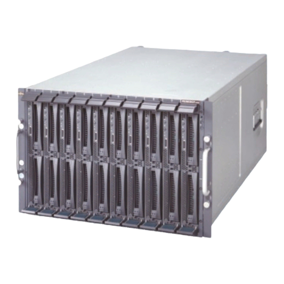
Introduction The PRIMERGY BX620 S2 server blade is a further model of the highly compact, powerful server blade which can be operated in the PRIMERGY BX600 basic unit. Figure 1: PRIMERGY BX620 S2 server blade As ultracompact systems, the BX620 S2 server blades with one or two CPUs are ideally suited for use in computer centers in companies and Internet service providers. - Page 6 BX620 S2 server blade on the PRIMERGY BX600 basic unit. It contains special information for installation, placing in service and operation of the PRIMERGY BX620 S2 server blade blade. All global information for server blade models for installation, placing in service and operation of PRIMERGY BX600 server blades is available in the manual “PRIMERGY BX600 basic unit”...
-
Page 7: Features
Introduction Features Further Sources of Information Further information is provided in: – the RemoteDeploy manual (only relevant for cloning server blades) – the technical manual for the rack – the manual for the monitor – the ServerView Server Management manual –... - Page 8 Features Introduction Only one SCSI HDD module can be installed if a PCI expansion module is installed. LAN Availability The BX620 S2 server blade has four Gigabit LAN channels. Usually two channels are connected with the switch blades. Each switch blade has ten 1-Gigabit downlink ports to connect the server blades and three uplink ports for 10/100/1000 Base TX.
- Page 9 Introduction Features The on-board SCSI-RAID controllers with HostRAID support (RAID-Levels 0 and 1) increase system availability. Server Management Server management is implemented via the supplied ServerView software and PDA (Prefailure Detection and Analyzing) technology from Fujitsu Siemens Computers. PDA warns of system errors or overloading before they occur so that preventive measures can be taken.
- Page 10 Features Introduction The flash EPROM program supplied with the Fujitsu Siemens utilities supports fast BIOS update. The two redundant and hot-swappable management blades with independent management LAN and COM ports ensure complete remote control. Together they facilitate remote diagnosis for system analysis, remote configuration, and remote restart should the operating system or hardware fail.
-
Page 11: Notational Conventions
Introduction Notational Conventions Notational Conventions The following notational conventions are used in this manual: Italics indicate commands, menu items or software programs. “Quotation marks” indicate names of chapters and terms that should be emphasized. Ê Text which follows this symbol describes activities that must be performed in the order given. - Page 12 Technical Data Introduction Approvals Product safety Global Europe ENEC Germany USA/Canada / CSA Japan VCCI Mechanical Values Width 286 mm Space requirement 470 mm (520 mm incl. levers and connectors) Height 43 mm (1 slot in the BX600 basic unit) Weight Max.
- Page 13 Introduction Technical Data Noise Level This data refers to the BX600 basic unit. Sound power level L (ISO 7779) 7.8 BA ≤ 59 dB(A) (in the Sound pressure level at bystander position (ISO 9296) standard configuration Rev. 1.0 U41595-J-Z156-1-76...
-
Page 15: Overview: Installation Steps
Overview: Installation Steps This chapter contains an overview of the steps required to install your BX620 S2 server blade in the PRIMERGY BX600 basic unit. Links will connect you to the sections with detailed descriptions of the individual steps. The information required for installing and placing in service the PRIMERGY BX600 basic unit can be found in the manual “PRIMERGY BX600 Basic Unit - Operating Manual”... - Page 16 Overview: Installation Steps – Local installation with or without ServerStart Since the local installation is the least convenient installation method, it is only recommended if the requirements for remote installation or cloning are not satisfied. If you wish to install an operating system that is not supported by Server- Start, you can perform the installation directly without using ServerStart.
-
Page 17: Important Information
If you have any questions, please contact your sales outlet or the customer service center of Fujitsu Siemens Computers. CAUTION! The actions described in these instructions should only be performed by technicians, service personnel or technical specialists. - Page 18 Notes On Safety Important Information CAUTION! Transport the device only in the original packaging or in packaging which protects it from knocks and jolts. Setup and Operation CAUTION! Observe the information for setting up your system and operating it in the manual “PRIMERGY BX600 Basic Unit”...
-
Page 19: Components With Electrostatic-Sensitive Devices
Important Information Components With Electrostatic-Sensitive Devices Components With Electrostatic-Sensitive Devices Electrostatic-sensitive components are identified by the following sticker: Figure 2: ESD label When you handle components fitted with ESDs, you must observe the following points under all circumstances: Always discharge static build-up (e.g. by touching a grounded object) before working. -
Page 20: Fcc Class A Compliance Statement
Consult the dealer or an experienced radio/TV technician for help. Fujitsu Siemens Computers is not responsible for any radio or television inter- ference caused by unauthorized modifications of this equipment or the substi- tution or attachment of connecting cables and equipment other than those specified by Fujitsu Siemens Computers. -
Page 21: Environmental Protection
Important Information Environmental Protection Environmental Protection Environmentally Friendly Product Design and Development This product has been designed in accordance with standards for “environmen- tally friendly product design and development”. This means that the designers have taken into account important criteria such as durability, selection of materials and coding, emissions, packaging, the ease with which the product can be dismantled and the extent to which it can be recycled. - Page 22 Environmental Protection Important Information Take-back, Recycling and Disposal For details on take-back and reuse of devices and consumables within Europe, contact your Fujitsu Siemens Computers branch office/subsidiary or our recycling center in Paderborn, Germany: Fujitsu Siemens Computers Recycling Center D-33106 Paderborn Tel.:...
-
Page 23: Installation Of The Hardware
Installation of the Hardware CAUTION! Observe the safety information in the chapter “Important Information” on page 13. The BX620 S2 server blade should not be exposed to any extreme ambient conditions (see the section “Technical Data” on page 7). Protect it from dust, moisture and heat. -
Page 24: Installing The Bx620 S2 Server Blade In The Bx600 Basic Unit
Installing the BX620 S2 Server Blade Installation of the Hardware Installing the BX620 S2 Server Blade in the BX600 Basic Unit A 4-way server blade occupies one slot in the BX600 basic unit. In all you can install five BX620 S2 server blades in a PRIMERGY BX600 basic unit. Different server blade models can also be operated together in a BX600 basic unit. - Page 25 Installation of the Hardware Installing the BX620 S2 Server Blade Figure 3: Removing a server blade dummy module Ê Release the locking mechanism of the ejecting handles by pressing the touch points on the inside of both handles (1) simultaneously. The ejecting handles of the dummy module will be disengaged.
- Page 26 Installing the BX620 S2 Server Blade Installation of the Hardware Installing a BX620 S2 Server Blade CAUTION! Read the safety information and the information on handling electro- static-sensitive components in the section “Components With Electro- static-Sensitive Devices” on page 15. Figure 4: Turning the eject handles into the unlocked position Ê...
- Page 27 Installation of the Hardware Installing the BX620 S2 Server Blade Figure 5: Installing a server blade Ê Push the server blade into the slot as far as possible while keeping the eject handles in the unlocked position. Please make sure that the server blade is mounted in the correct direction.
- Page 28 Installing the BX620 S2 Server Blade Installation of the Hardware Figure 6: Final engaging of the locking mechanism Ê Press the eject handles to enable the locking mechanism to engage fully. Removing the BX620 S2 Server Blade The BX620 S2 server blade is removed in the same way as the dummy module (see “Removing the Dummy Module”...
-
Page 29: Connecting The Bx620 S2 Server Blade
Installation of the Hardware Connecting a 4-way server blade Connecting the BX620 S2 Server Blade All connections required for operating the BX620 S2 server blade are made via the midplane of the BX600 basic unit. When the BX620 S2 server blade is installed in the BX600 basic unit, plug contacts to the midplane automatically set up contacts to the following modules on the rear of the BX600 basic unit: –... - Page 30 Connecting a 4-way server blade Installation of the Hardware For connection to an external device via the USB/VGA connector of the BX620 S2 server blade you require a special cable (see figure 8). Figure 8: USB/VGA cable The USB/VGA cable is part of the delivery scope of the PRIMERGY BX600 basic unit.
-
Page 31: Preparation For Use And Operation
Preparation for Use and Operation CAUTION! Observe the safety information in the chapter “Important Information” on page 13. This chapter contains the information which is required for placing in service and operating the BX620 S2 server blade after it has been installed in the PRIMERGY BX600 basic unit. -
Page 32: Operating And Connection Panel
Operating and Connection Panel Preparation for Use and Operation Operating and Connection Panel Figure 9: BX620 S2 server blade: Operating panel The following operating, indicator and connection elements are provided (figure 9 on page 28): Power button fully compatible with Advanced Configuration Power Interface (ACPI) When the BX600 basic unit is switched on (5 V standby power is present) and the server blade is switched OFF and you press the power... - Page 33 Preparation for Use and Operation Operating and Connection Panel KVM (keyboard/video/mouse) button Pressing the KVM button switches the KVM to this server blade. Power/Select indicator (bicolor LED) Dark: The BX600 basic unit is switched OFF, no 5 V standby power is present or this server blade is not correctly inserted.
-
Page 34: Switching A Bx620 S2 Server Blade On/Off
Switching the Server Blade On/Off Preparation for Use and Operation NIC indicator (green LED) Dark: System or server blade is switched OFF and LAN interface not working. Lights green: LAN is connected. Blinks green: LAN is active. USB/VGA connector Adapter connector for two USB ports for external CD/FD drives and one VGA port. -
Page 35: Configuring A Bx620 S2 Server Blade With Serverstart
Configuring the BX620 S2 Server Blade Switching the Server Blade On/Off Switching the BX620 S2 Server Blade On/Off Using the Operating Panel The BX600 basic unit must be switched on. The server blade can be switched on and off as follows: –... - Page 36 Switching the Server Blade On/Off Configuring the BX620 S2 Server Blade Reference Installation A reference installation of a server blade with the aid of ServerStart serves as a basis for a clone image. The image is created and then used by RemoteDeploy for quick installation and configuration of further server blades.
- Page 37 Configuring the BX620 S2 Server Blade Switching the Server Blade On/Off Software Preparation Booting from the CD-ROM drive Boot the relevant server blade from the ServerStart CD to install the operating system. In some cases you will have to change some settings to do this: Ê...
-
Page 38: Updating Firmware (Bios And Bmc)
Updating Firmware (BIOS and BMC) Preparation for Use and Operation Updating Firmware (BIOS and BMC) All files required for updating the PRIMERGY BX600 basic unit components are available from http://download.fujitsu-siemens.com. You can update both the firmware of the server blade BIOS and the firmware of the server blade BMC. -
Page 39: Bios Setup
BIOS Setup In the BIOS setup you can set up the system functions and the hardware config- uration of a server blade. The scope of the displayed BIOS parameters may depend on the config- uration. On delivery, the default settings of the server blade are active. You can change these settings in the BIOS setup. - Page 40 BIOS Setup USB Function [ 45] USB 2.0 Controller [ 45] Legacy USB Support [ 45] Peripheral Configuration [ 46] Serial Port 1(Address/IRQ) [ 46] PCI Configuration [ 47] Server [ 48] Memory Scrubbing [ 48] Memory Spare [ 49] DIMM x,y [ 49] CPUx Status [ 49] Power –...
-
Page 41: Entering The Bios Setup
BIOS Setup Entering the BIOS Setup Entering the BIOS Setup Ê Restart the server blade (cold or warm start). Ê Press the [F2] function key. Ê Enter the setup password (if defined) and confirm by pressing Enter. Navigating in the BIOS Setup The BIOS setup screen has the following structure: Figure 10: Structure of the BIOS setup screen Rev. - Page 42 Navigating in the BIOS Setup BIOS Setup Menu bar Use the À and  keys to select a menu (Main, Advanced, ...) from the menu bar. Work area The work area (left part of the screen) shows the menu information and possible settings for the selected menu.
-
Page 43: Main Menu
BIOS Setup Main Menu Main Menu Figure 11: Main menu BIOS Version indicates the BIOS version. BMC F/W Version indicates the firmware version of the baseboard management controller (BMC). System Time / System Date used to set the system date and time. The system time has the format HH:MM:SS. -
Page 44: Advanced Menu
Advanced Menu BIOS Setup Sync RTC with Mgmt. Blade switches synchronization of the real-time clock and the time of the management blade on (Enabled) or off (Disabled). System Memory indicates the size of the available main memory. Memory Test defines whether a memory test is performed during BIOS startup (Enabled) or not (Disabled). - Page 45 BIOS Setup Advanced Menu Reset Configuration Data defines whether the configuration data is reinitialized when the server blade is started. When the server blade is started, the plug&play functionality detects the new configuration data and uses it to initialize the installed boards and drives.
-
Page 46: Server Management
Advanced Menu BIOS Setup Peripheral Configuration opens a submenu for setting interface and controller options (see section “Peripheral Configuration” on page 46). PCI Configuration opens a submenu for setting options for the PCI slots and PCI compo- nents on the mainboard (see section “PCI Configuration” on page 47). Server opens a submenu for setting memory and CPU administration options (see section “Server”... - Page 47 BIOS Setup Advanced Menu If the operating system has no server management process, this option must be set to Disabled to prevent the server management firmware from initiating a restart by mistake. The waiting period and the server management process (agent) are installed with ServerView.
-
Page 48: Console Redirection
Advanced Menu BIOS Setup 6.4.2 Console Redirection Figure 14: Terminal communication Com Port Address defines the interface for communicating with the terminal (On-board COM A or Disabled). Selecting Disabled switches the terminal functionality off and hides the remaining items of this submenu. Console Type defines the transmission protocol for the communication with the terminal. -
Page 49: Advanced Chipset Feature
BIOS Setup Advanced Menu 6.4.3 Advanced Chipset Feature Figure 15: Advanced chipset properties USB Function defines whether the USB hardware is switched on (Enabled) or off (Disabled). If this menu item is set to Disabled, the USB controller is not detected by any operating system and USB devices cannot be used. -
Page 50: Peripheral Configuration
Advanced Menu BIOS Setup When the emulation is switched on, you can also use the USB keyboard or USB mouse under operating systems which do not support USB. If USB is supported by the operating system, the operating system can be started from a USB device. -
Page 51: Pci Configuration
BIOS Setup Advanced Menu 6.4.5 PCI Configuration Figure 17: PCI configuration The menu items in this submenu allow you to define whether the BIOS of the corresponding devices is to be started during the POST (Enabled) or not (Disabled). If you want to boot from one of these devices, the corresponding BIOS must be started. -
Page 52: Server
Advanced Menu BIOS Setup 6.4.6 Server Figure 18: Memory and CPU administration Memory Scrubbing defines whether the memory is constantly monitored, correcting all correctable errors (Enabled), or not (Disabled). Memory scrubbing also prevents most non-correctable memory errors, as these usually occur as a result of an accumulation of correctable memory errors. - Page 53 BIOS Setup Advanced Menu Memory Spare defines whether a memory is to be used as reserve (Enabled) or not (Disabled). The BIOS uses one memory bank as reserve in case too many correctable errors occur in another memory bank. Before any non- correctable errors occur, the contents of this memory bank are redirected to the spare bank.
-
Page 54: Power Menu
Power Menu BIOS Setup Power Menu Figure 19: Power management APM 1.2 Interface Disable or Enable APM 1.2 Interface defines whether the APM interface is switched on (Enabled) or off (Disabled). Rev. 1.0 U41595-J-Z156-1-76... -
Page 55: Boot Menu
BIOS Setup Boot Menu After Power Failure defines whether the server is to be restarted after a power failure or not: Stay Off Leave the server switched off after a power failure Last State Restore the last state of the server before the power failure, i.e. if the server was switched off, leave it off, if it was running, switch it back on. - Page 56 Boot Menu BIOS Setup Boot Device Priority opens a submenu in which you define the order in which the available devices are searched for the system files required by the system BIOS during booting. Hard Disk Drives opens a submenu in which you define the order in which the available hard disk drives are searched for the system files required by the system BIOS during booting.
-
Page 57: Security Menu
BIOS Setup Security Menu Security Menu Figure 21: Security menu Supervisor Password / User Password indicates whether the corresponding password is used (Installed) or not (Not Installed). Change Supervisor Password If you select this item and press Enter, a dialog box opens in which you can define a supervisor password. - Page 58 Security Menu BIOS Setup Clear User Password If you select this item and press Enter, a dialog box opens in which you can delete the user password. Password Check defines whether a password is required for starting the system. Entering the BIOS setup always requires a password (if defined).
-
Page 59: Exit Menu
BIOS Setup Exit Menu Exit Menu Figure 22: Exit menu Save Changes and Exit saves all parameter changes made in the current session and exits the BIOS setup. Discard Changes and Exit discards all parameter changes made in the current session and exits the BIOS setup. -
Page 61: Troubleshooting And Tips
Troubleshooting and Tips CAUTION! Observe the safety information in the chapter “Important Information” on page 13. All information on how to behave in the event of faults which can occur during operation of server blades in the PRIMERGY BX600 basic unit is provided in the manual “PRIMERGY BX600 Basic Unit”... -
Page 63: Bx620 S2 Server Blade Components
BX620 S2 Server Blade Components In this chapter you will learn how to replace or add hardware components in your PRIMERGY BX620 S2 server blade. Opening the BX620 S2 Server Blade CAUTION! Read the safety information and the information on handling electro- static-sensitive components in the section “Components With Electro-... -
Page 64: Overview
Overview BX620 S2 Server Blade Components Overview Figure 24: BX600 BX620 S2 server blade Figure 24 above shows the positions of the components of the BX620 S2 server blade for which a description of installation or replacement is provided in this chapter. Rev. -
Page 65: Memory
BX620 S2 Server Blade Components Memory Sockets of the three memory banks for DDR2 400 SDRAM modules HDD module 1 HDD module 2 (can be replaced with a front PCI expansion module) Lithium battery Optional I/O module (FC daughter card or Ethernet daughter card) The SDRAM modules, FC or Ethernet daughter card and PCI riser card must be installed on the server blade before it is inserted in the BX600 basic unit. - Page 66 Memory BX620 S2 Server Blade Components Assembly Instructions Observe the correct sequence when plugging in the DDR2 400 SDRAM modules. D I M M B a n k 0 B a n k 0 D I M M D I M M B a n k 1 D I M M D I M M...
- Page 67 BX620 S2 Server Blade Components Memory Installing SDRAM Modules CAUTION! Read the safety information and the information on handling electro- static-sensitive components in the section “Components With Electro- static-Sensitive Devices” on page 15. Be very careful when installing an SDRAM module, as too much pressure can damage the ejector levers.
- Page 68 Memory BX620 S2 Server Blade Components Figure 28: Inserting an SDRAM module Ê Position the SDRAM module so that the notch (arrow) aligns with the socket on the server blade. Insert the SDRAM module into the socket and press firmly in the direction of the arrow until it is seated correctly. Figure 29: Locking the SDRAM module Ê...
-
Page 69: Hard Disk Drives
BX620 S2 Server Blade Components Hard Disk Drives The BIOS automatically detects, sizes and initializes memory according to the size and speed of the installed SDRAMs and reports the memory size and allocation to the system via the configuration registers. The SDRAM modules are removed in reverse order. -
Page 70: Replacement Of The Hdd Module During Operation
Hard Disk Drives BX620 S2 Server Blade Components 8.4.1 Replacement of the HDD Module During Operation A hard disk drive module may be swapped during operation only if the orange LED on the hard disk drive module is lit continuously. CAUTION! Never remove a hard disk drive module during operation if you are not sure that it is operated on a RAID controller and is part of a disk array that... - Page 71 BX620 S2 Server Blade Components Hard Disk Drives Removing a Hard Disk Drive Module Figure 31: Removing a hard disk drive module Ê Press the locking button (1) until the locking mechanism of the module handle disengages and then swing up the module handle (2) and remove the hard disk module from the bay (3).
-
Page 72: Front Pci Expansion Module
Front PCI Expansion Module BX620 S2 Server Blade Components Front PCI Expansion Module The BX620 S2 server blade can be equipped with a proprietary expansion module located on the front for a standard half-size PCI card via a PCI riser card. - Page 73 BX620 S2 Server Blade Components Front PCI Expansion Module Installing a PCI Expansion Module CAUTION! Read the safety information and the information on handling electro- static-sensitive components in the section “Components With Electro- static-Sensitive Devices” on page 15. BX620 S2 server blades with PCI modules must be installed in slots 5 and 6 of the BX600 basic unit only.
- Page 74 Front PCI Expansion Module BX620 S2 Server Blade Components Figure 34: Removing the bezel from above the SCSI hard disk drive module slot Ê Turn the bezel forward (1) and remove it (2). Figure 35: Removing the front bezel Ê Remove the front bezel from the PCI module. Unscrew the two cross-head screws (A), push the bezel a little to the left and pull it off.
- Page 75 BX620 S2 Server Blade Components Front PCI Expansion Module Figure 36: Fixing a PCI card in a PCI riser card Ê Push the PCI card into the socket of the riser card (1) and fix the PCI card with a cross-head screw (2). Figure 37: Mounting the PCI bridge module Ê...
- Page 76 Front PCI Expansion Module BX620 S2 Server Blade Components Figure 38: Inserting the module Ê Insert the PCI module into the free hard disk module slot. Figure 39: Connecting the PCI module The PCI module connects to the PCI bridge as soon as it reaches its final position.
- Page 77 BX620 S2 Server Blade Components Front PCI Expansion Module Figure 40: Fastening the PCI module Ê Fasten the PCI module using the two screws you undid when removing the bezel above from the hard disk drive module slot (see figure 34 on page 70). Ê...
-
Page 78: Optional I/O Module
Optional I/O Module BX620 S2 Server Blade Components Optional I/O Module The BX620 S2 server blade can be equipped with a Fibre Channel (FC) I/O module or with an addional Ethernet I/O module. For this purpose the BX620 S2 server blade provides a proprietary PCI X 64-bit expansion slot for a an FC daughter card or an Ethernet daughter card. - Page 79 BX620 S2 Server Blade Components Optional I/O Module Figure 43: Gigabit Ethernet daughter card The Gigabit Ethernet daughter card provides two 1-Gbit/s Ethernet ports. At least one Gigabit Ethernet pass-thru blade is required on the rear of the BX600 basic unit to connect these additional LAN ports. For more information see the manual “PRIMERGY BX600 Basic Unit”...
- Page 80 Optional I/O Module BX620 S2 Server Blade Components Installing an I/O Daughter Card CAUTION! Read the safety information and the information on handling electro- static-sensitive components in the section “Components With Electro- static-Sensitive Devices” on page 15. Ê Remove the cover plate from the server blade (see “Opening the BX620 S2 Server Blade”...
- Page 81 BX620 S2 Server Blade Components Optional I/O Module Figure 45: Installing an I/O daughter card Ê Fix the I/O daughter card with three screws. Rev. 1.0 U41595-J-Z156-1-76...
-
Page 82: Exchanging The Battery
Exchanging the Battery BX620 S2 Server Blade Components Exchanging the Battery In order to save the system information permanently, a lithium battery is installed to provide the CMOS memory with a current. When the charge is too low or the battery is empty, a corresponding error message is provided. The lithium battery must then be replaced. -
Page 83: Abbreviations
Abbreviations ASR&R Automatic Server Reconfiguration and Restart BIOS Basic Input-Output System Compact Disk Communication Central Processing Unit DBMS Database Management System Double Data Rate (RAM) DIMM Dual Inline Memory Module Digital Video Disk Error Correcting Code Error Detection Code Electromagnetic Compatibility Electrostatic Discharge Rev. - Page 84 Abbreviations Fibre Channel Global Array Manager Hard Disk Drive Height Unit Input/Output Identification Integrated Drive Electronics Internet Protocol Local Area Network Liquid Crystal Display Liquid Emitting Diode Memory Controller Hub Manually Retention Latch Network Interface Card Rev. 1.0 U41595-J-Z156-1-76...
- Page 85 Abbreviations Non Maskable Interrupt Peripheral Component Interconnect Prefailure Detection and Analyzing Power Supply Unit RAID Redundant Arrays of Independent Disks Read-Only Memory Storage Area Network Single Connector Attachment SCSI Small Computer System Interface Server Configuration Utility Small Form Factor Pluggable Universal Serial Bus Video Graphics Adapter Vital Product Data...
- Page 86 Abbreviations Wakeup on LAN Rev. 1.0 U41595-J-Z156-1-76...
-
Page 87: Related Publications
Related publications PRIMERGY manuals are available in PDF format on the ServerBooks CD. The ServerBooks CD is part of the PRIMERGY ServerView Suite delivered with each server system. The PDF files for the manuals can also be downloaded free of charge from the Internet. - Page 88 Related publications [12] PRIMERGY BX Blade Server Systems: LAN Switch Blade - User Interface Description User Guide [13] PRIMERGY BX Blade Server Systems: RemoteView Management Blade - User Interface Description User Guide Rev. 1.0 U41595-J-Z156-1-76...
-
Page 89: Index
Index CPU 3 adding server blade 20 data manipulation 1 approvals delivery note 19 product safety 8 dimensions 8 ASR&R 4 disposal, of devices 18 availability 4 dummy module installing 20 battery server blade 20 exchanging 78 server blade 78 ECC 4 BIOS setup 35 electromagnetic compatibility 7, 15... - Page 90 Index HDD 65 battery 78 SDRAM module 61 connection panel 28 control panel 28 controls 28 lithium battery 14 CPU 3 low-voltage directive 7, 15 dummy module 20 hard disk drive 3 indicator elements 28 meaning of the symbols 7 memory 3, 61 memory SDRAM module 61...
- Page 91 Comments Fujitsu Siemens Computers GmbH User Documentation 33094 Paderborn Suggestions Germany Corrections Fax: (++49) 700 / 372 00001 email: manuals@fujitsu-siemens.com http://manuals.fujitsu-siemens.com Submitted by Comments on PRIMERGY BX620 S2 2-way Server Blade U41595-J-Z156-1-76...
- Page 93 Comments Fujitsu Siemens Computers GmbH User Documentation 33094 Paderborn Suggestions Germany Corrections Fax: (++49) 700 / 372 00001 email: manuals@fujitsu-siemens.com http://manuals.fujitsu-siemens.com Submitted by Comments on PRIMERGY BX620 S2 2-way Server Blade U41595-J-Z156-1-76...
- Page 95 Copyright Fujitsu Technology Solutions, 2009 Hinweise zum vorliegenden Dokument Zum 1. April 2009 ist Fujitsu Siemens Computers in den alleinigen Besitz von Fujitsu übergegangen. Diese neue Tochtergesellschaft von Fujitsu trägt seit- dem den Namen Fujitsu Technology Solutions.
Need help?
Do you have a question about the Primergy BX620 S2 and is the answer not in the manual?
Questions and answers