Fujitsu Siemens Computers PRIMERGY TX120 Operating Manual
Fujitso primergy tx120 operating manual
Hide thumbs
Also See for PRIMERGY TX120:
- Options manual (60 pages) ,
- Price list (453 pages) ,
- Options manual (61 pages)
Table of Contents
Advertisement
Quick Links
Advertisement
Table of Contents

Related Manuals for Fujitsu Siemens Computers PRIMERGY TX120


Summary of Contents for Fujitsu Siemens Computers PRIMERGY TX120
- Page 1 PRIMERGY TX120 Server Operating Manual Edition July 2007...
-
Page 2: Copyright And Trademarks
Gesellschaft für Technik-Dokumentation mbH www.cognitas.de Copyright and Trademarks Copyright © 2007 Fujitsu Siemens Computers GmbH. All rights reserved. Delivery subject to availability; right of technical modifications reserved. All hardware and software names used are trademarks of their respective manufacturers. -
Page 3: Table Of Contents
Connecting the server to the mains ....41 Notes on connecting/disconnecting cables ..42 TX120 ....7 . - Page 4 ......44 ....52 Operating Manual ... . . 57 TX120...
- Page 5 Index ........79 TX120 Operating Manual...
-
Page 7: Introduction
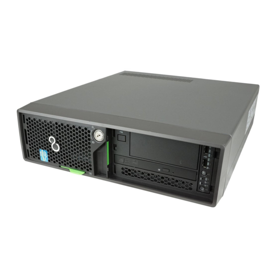
Introduction The PRIMERGY TX120 server is an Intel-based server for small and medium- sized networks and can be used in the horizontal position or as a desktop model. The PRIMERGY TX120 server features exceptionally low energy consumption, very quiet running and a compact size. As a result, it is also the ideal solution for home and small offices. - Page 8 – Technical manual for the system board D2550 (PDF file available on the ServerBooks DVD supplied) – “BIOS Setup” (PDF file available on the ServerBooks DVD supplied) – “PRIMERGY TX120 Server Options Guide” (PDF file available on the ServerBooks DVD) The “Options Guide” describes the server expansion and modifi- cation options.
- Page 9 – Manual for the remote testing and diagnostic system RemoteView – Documentation for boards and drives – Documentation for your operating system – Information files on your operating system (See also “Literature” on page TX120 Documentation overview 77.) Operating Manual...
-
Page 10: Features
(RAID level 0, 1, 1E). A separate utility is available to the controller for IME configuration. For further information, refer to the “Integrated Mirroring User’s Guide” on the ServerBooks DVD (select “Controllers” from the menu). 77). Operating Manual Introduction TX120... - Page 11 ASR&R (Automatic Server Reconfiguration and Restart) restarts the system in case of an error and automatically “hides” the defective system components. The PDA (Prefailure Detection and Analyzing) technology from Fujitsu Siemens Computers analyzes and monitors all components that are critical for system reliability.
- Page 12 Full-coverage alarm management System Error and Event Log (SEL) reading and processing More information about the iRMC can be found in the "PRIMERGY ServerView Suite - integrated Remote Management Controller (iRMC)" manual (see ature” on page 77). Operating Manual Introduction “Liter- TX120...
- Page 13 Server Management is implemented using theServerView software supplied combined with PDA (Prefailure Detection and Analyzing) technology from Fujitsu Siemens Computers. PDA reports the threat of a system error or overload at an early stage, allowing preventive measures to be taken.
- Page 14 With the iRMC (integrated Remote Management Controller) on the system board and the optional remote testing and diagnostic system RemoteView, the PRIMERGY TX120 server can also be maintained and serviced remotely. This enables remote diagnosis for system analysis, remote configuration and remote restart should the operating system or hardware fail.
-
Page 15: Notational Conventions
CAUTION! pay particular attention to texts marked with this symbol. Failure to observe this warning may endanger your life, destroy the system or lead to the loss of data. indicates additional information, notes and tips. TX120 Notational conventions Operating Manual... -
Page 16: Technical Data
FCC class A CNS 13438 class A; VCCI class A AS/NZS CISPR 22 class A / GB 9254 class A GB 17625 EN 61000-3-3 EN 55024, EN 300386 Low Voltage Directive 2006/95/EC (Product Safety) Electromagnetic Compatibility 2004/108/EC Operating Manual Introduction TX120... - Page 17 Condensation during operation must be avoided! Noise level Sound power level L Sound pressure level at adjacent workstation (ISO 9296) TX120 340 mm 399 mm 99 mm (104 mm with feet) EN 60721 / IEC 721 Part 3-3 EN 60721 / IEC 721 Part 3-2 15 °C ...
-
Page 19: Installation Steps, Overview
41). Ê Familiarize yourself with the controls and displays on the front and rear of the server (see section “Controls and displays” on page TX120 “Unpacking the server” on page “Additional server documen- “Setting up the server” on page “Notes on connecting/disconnecting cables”... - Page 20 You will find more information on installing the server remotely or locally in the ServerStart manual. This manual contains the instal- lation steps (“Quick Step Guide”). A corresponding file in PDF format is included on the ServerBooks DVD. 52). Operating Manual “Configuration or section “Configu- TX120...
-
Page 21: Important Information
Any unauthorized opening and improper repairs could expose the user to risks (electric shock, energy hazards, fire hazards) and could also damage the equipment. Any unauthorized opening of the device will result in the invalidation of the warranty and exclusion from all liability. TX120 Operating Manual... - Page 22 This device must only be connected to properly grounded shock- proof sockets or insulated sockets of the rack's internal power supply with tested and approved power cables. Ensure that the device is connected to a grounded shockproof socket close to the device. 16). Operating Manual Important information section TX120...
- Page 23 (electric shock hazard, short circuit). In emergencies (e.g. damaged casing, controls or cables, penetration of liquids or foreign bodies), switch off the server immediately, remove all power plugs and contact your sales outlet or customer service team. TX120 Operating Manual Safety...
- Page 24 Only set screen resolutions and refresh rates that are specified in the operating manual for the monitor. Otherwise, you may damage your monitor. If you are in any doubt, contact your sales outlet or customer service center. Operating Manual Important information TX120...
- Page 25 All batteries containing pollutants are marked with a symbol (a crossed-out garbage can). In addition, the marking is provided with the chemical symbol of the heavy metal decisive for the classification as a pollutant: Cd Cadmium Hg Mercury Pb Lead TX120 “Literature” on page 77). 77). Operating Manual Safety...
- Page 26 The CD/DVD drive contains a light-emitting diode (LED), which under certain circumstances produces a laser beam stronger than laser class 1. Looking directly at this beam is dangerous. Never remove parts of the CD/DVD drive casing! Operating Manual Important information TX120...
- Page 27 Do not touch any connectors or conduction paths on an ESD. Place all the components on a pad which is free of electrostatic charge. For a detailed description of how to handle ESD components, see the relevant European or international standards (EN 61340-5-1, ANSI/ESD S20.20). TX120 Operating Manual Safety...
-
Page 28: Ce Conformity
“Cleaning the server” on Operating Manual Important information TX120... -
Page 29: Transporting The Server
Consult the dealer or an experienced radio/TV technician for help. Fujitsu Siemens Computers is not responsible for any radio or television inter- ference caused by unauthorized modifications of this equipment or the substi- tution or attachment of connecting cables and equipment other than those specified by Fujitsu Siemens Computers. -
Page 30: Environmental Protection
Important information Environmental protection Environmentally-friendly product design and development This product has been designed in accordance with the Fujitsu Siemens Computers standard for “environmentally friendly product design and devel- opment”. This means that key factors such as durability, selection and labeling of materials, emissions, packaging, ease of dismantling and recycling have been taken into account. - Page 31 Details regarding the return and recycling of devices and consumables within Europe can also be found in the “Returning used devices” manual, via your local Fujitsu Siemens Computers branch or from our recycling center in Paderborn: Fujitsu Siemens Computers Recycling Center D-33106 Paderborn Tel.
-
Page 33: Hardware Installation
“Acclimatization the difference between the operating environment temperature and the temperature to which the server was exposed previously (outside, transport or storage temperature). TX120 17). Protect the server from dust, Minimum acclimatization time time”, the temperature difference refers to Operating Manual “Important information”... -
Page 34: Unpacking The Server
The product name and serial number of the product can be found on the identi- fication rating plate. Ê Notify your supplier immediately should you discover that the items delivered do not correspond to the delivery note. “Important information” on page 21 Operating Manual Hardware installation TX120... -
Page 35: Setting Up The Server
40 on page Ê Connect the server to the mains (see section mains” on page 41). TX120 36) or horizontal position “Notes on connecting/disconnecting cables” “Connecting the server to the Operating Manual Setting up the server 39). -
Page 36: Positioning The Server Vertically
The stabilizers must be attached in the correct direction (see figure page 38). Clipping the stabilizers together Figure 2: Clipping the stabilizer together Ê Clip the stabilizers together in the direction of the arrow as far as the marking line (a). Operating Manual Hardware installation 4 on TX120... - Page 37 You may have to adjust the width of the stabilizers. Ê Slide your thumb or forefinger (1) under the locking springs (a). Ê Press the locking springs (a) upwards (2). Ê With the locking springs (a) disengaged, pull the stabilizer apart (3). Operating Manual TX120...
- Page 38 Hardware installation Placing the server on the stabilizers Figure 4: Placing the server on stabilizers Ê Place the server on the stabilizers (1). Position the stabilizers between the rubber feet (a). Ê Press the stabilizers together (2). Operating Manual TX120...
-
Page 39: Positioning The Server Horizontally
If the server is positioned horizontally, the rubber feet must be attached! The stabilizers must be attached in the correct direction (see figure 5). Figure 5: Positioning the server horizontally Ê Place the server on its four rubber feet. TX120 Operating Manual Setting up the server... -
Page 40: Connecting Devices To The Server
Two additional USB ports are located on the front of the server (see figure page 44). 5 Monitor port (VGA) (blue) 6 Keyboard port (PS/2) (purple) 7 Mouse port (PS/2) (green) Operating Manual Hardware installation “Literature” on 9 on TX120... -
Page 41: Connecting The Server To The Mains
Ê Insert the mains plug into an earthing contact socket (2) in the internal supply network. Ê Secure the power cord in the terminal so the insulated connector cannot be disconnected from the server accidentally (3). TX120 Connecting the server to the mains Operating Manual... -
Page 42: Notes On Connecting/Disconnecting Cables
Ê Turn off all power and equipment switches. Ê Disconnect all power plugs from the grounded shockproof sockets. Ê Unplug all data communication cables from the utility sockets. Ê Disconnect the relevant cables from the server and all the peripherals. Operating Manual Hardware installation TX120... -
Page 43: Starting Up And Operation
Follow the safety instructions in chapter page Opening the drive cover Figure 8: Opening the drive cover Ê Turn the key counterclockwise (1). Ê Open the drive cover in the direction of the arrow (2). TX120 “Important information” on Operating Manual... -
Page 44: Controls And Displays
NMI button 2 x USB ports Power-on indicator Hard disk drive activity indicator 7 6 5 4 Global error indicator ID indicator ID button 10 Reset button 11 On/Off button 12 CD-/DVD drive indicator Operating Manual Starting up and operation TX120... - Page 45 Do not press! The NMI button may only be used by service personnel. Reset button Pressing the reset button reboots the system. ID button When this button is pressed, the ID display (blue) on the front of the server lights up. TX120 Operating Manual Controls and displays...
- Page 46 Lights up blue when the system has been selected by pressing the ID button. To deactivate, press the button again. The ID indicator can also be activated via ServerView and its status reported to ServerView. Starting up and operation Operating Manual TX120...
- Page 47 – Two fast flashes/pause: HDD Hot Spare (Hot spare drive active. The corresponding drive has failed). 2 HDD BUSY (green) – Lights: HDD in active phase – Does not light: HDD inactive (drive inactive) TX120 9 on page Operating Manual Controls and displays...
-
Page 48: Rear Of Server
Does not light up for a LAN transfer rate of 10 Mbps. 4 LAN link/active indicator (service LAN) Lights up green if a LAN connection exists. Does not light up if no LAN connection exists. Flashes green when a LAN transfer is in progress. Operating Manual Starting up and operation TX120... -
Page 49: Switching The Server On And Off
Ê Press the On/Off button (item 11 in The power-on indicator lights up green (item 5 in The server is switched on, performs a system test and boots the operating system. TX120 Switching the server on and off 57). figure 9 on page 44) lights orange. - Page 50 The server is switched on by an IPMI console via serial port COM1 (item 4 figure 6 on page 40) or via the service LAN connection (item 3 in on page 40). Starting up and operation figure 9 on page 44) lights green. Operating Manual figure 6 TX120...
-
Page 51: Configuring The Server
The software that can be installed depends on your server’s hardware configuration. This configuration is detected automatically. Descriptions of operating systems not covered in the RAID controller manual are provided in the appropriate readme files on the driver CDs. TX120 Configuring the server Operating Manual... -
Page 52: Configuration Without Serverstart
Wipe the server and monitor casing with a dry cloth. If particularly dirty, use a cloth that has been moistened in a mild domestic detergent and then carefully wrung out. “Literature” on page 77). “Configuring onboard SAS Operating Manual Starting up and operation TX120... -
Page 53: Property And Data Protection
By combining these options you can achieve optimum protection for your system. A detailed description of the Security menu and how to assign passwords can be found in the “BIOS Setup” documentation on the PRIMERGY ServerBooks DVD (see also TX120 “Literature” on page 77). Operating Manual... -
Page 55: Troubleshooting And Tips
Power supply overloaded Ê Disconnect the server power plug(s) from the power socket(s). Ê Wait a few seconds before you plug it/them into the grounded socket(s) again. Ê Switch on your server. TX120 “Hardware installation” on page Operating Manual... -
Page 56: Server Switches Itself Off
(if it is plugged in with a connector). If a separate graphics card is installed in the server, then the monitor cable must be connected to the graphics card. Ê Switch on the monitor and the server. Troubleshooting and tips Operating Manual TX120... -
Page 57: Flickering Stripes On Monitor Screen
Ê Refer to the documentation for your operating system or the software for the screen controller for details of how to set the correct horizontal frequency for your monitor, and follow the procedure accordingly. TX120 Flickering stripes on monitor screen Operating Manual... -
Page 58: No Mouse Pointer Displayed On Screen
If the date and time are still wrong after the server has been switched off and back on again, replace the lithium battery (for a description refer to the Technical Manual for the D2550 system board) or contact our customer service team. Troubleshooting and tips Operating Manual TX120... -
Page 59: Drives Reported As "Dead" When Starting System
Error message on screen The meaning of the error message is explained in the manual for the BIOS-Setup and in the documentation for the relevant components and programs on the PRIMERGY ServerBooks DVD. TX120 “Removing the HDD module” on page Operating Manual “Installing... -
Page 61: Hot-Plug Hard Disk Drives
Up to four hot-pluggable hard disk drives can be installed in the PRIMERGY TX120 server. The hard disk drives which can be ordered for the PRIMERGY TX120 are supplied already mounted in an installation frame so that defective hard disk drives can be replaced and new drives can be added during operation. -
Page 62: Handling Hard Disk Drives And Hdd Modules
(operating environment/ outside) Table 2: Acclimatization times for HDD modules Always set the HDD module down carefully, with the large surface facing downwards to prevent it from tipping over. Minimum acclimatization time Operating Manual Hot-plug hard disk drives (hours) TX120... -
Page 63: Removing/Installing The Dummy Module
EMC regulations (regulations regarding electromagnetic compatibility), and for protection against fire. Ensure that the dummy module engages correctly in the slot. TX120 Removing/Installing the dummy module Operating Manual... -
Page 64: Installing/Removing The Hdd Module
Figure 12: Unlocking the HDD module Ê Release the locking mechanism by pressing the lock together (1). Ê Push the handle of the HDD module fully in the direction of the arrow (2). The HDD module is now unlocked. Operating Manual TX120... - Page 65 Ê Carefully push the HDD module into the empty mounting location (1) until it stops. Ê Push the handle completely in the direction of the arrow (2) until the locking mechanism engages. TX120 Installing/Removing the HDD module “Unlocking the HDD Operating Manual...
- Page 66 This period is necessary for the RAID controller to recognize that an HDD module has been removed and for the hard disk drive to come to a stop. Ê Pull the HDD module out completely. Hot-plug hard disk drives “Indicators on the HDD module” on “Unlocking the HDD Operating Manual TX120...
- Page 67 EMC regulations (regulations regarding electromagnetic compatibility), and for protection against fire. Ensure that the dummy module engages correctly in the slot. TX120 Installing/Removing the HDD module “Unlocking the HDD module” Operating Manual...
-
Page 69: Abbreviations
American National Standards Institute ASR&R Automatic Server Reconfiguration and Restart Advanced Technology Attachments BIOS Basic Input-Output System Cache Coherency Compact Disk CD-ROM Compact Disk-Read Only Memory Cylinder Head Sector CMOS Complementary Metal Oxide Semiconductor Communications Central Processing Unit TX120 Operating Manual... - Page 70 Error Checking and Correcting Extended Capabilities Port EEPROM Electrically Erasable Programmable Read-Only Memory Elektrostatisch gefährdete Bauteile (components in danger of electro- static discharge) Emergency Management Port Enhanced Parallel Port Elektromagnetische Verträglichkeit (electromagnetic compatibility) EPROM Erasable Programmable Read-Only Memory Operating Manual TX120...
- Page 71 ElectroStatic Discharge (elektrostatische Entladung) File Allocation Table Front Panel Controller Field Replaceable Unit Front Side Bus Graphical User Interface Hard Disk Drive Hot-Swap Controller Height Unit I²C Inter-Integrated Circuit Input/Output Intelligent Chassis Management Identification Integrated Drive Electronics TX120 Operating Manual Abbreviations...
- Page 72 Intelligent Platform Management Interface iRMC integrated Remote Management Controller Interrupt Request Line Local Area Network Logical Block Address Liquid Crystal Display Light Emitting Diode Logical Unit Number Low-Voltage Differential SCSI LichtWellenLeiter (fiber optic cable) Manual Retention Latch Multi Mode Faser Operating Manual TX120...
- Page 73 Operating System Peripheral Component Interconnect Prefailure Detection and Analysing Portable Data Format POST Power ON Self Test PS/2 Personal System/2 RAID Redundant Arrays of Independent Disks Random Access Memory Read-Only Memory Remote Service Board Real Time Clock TX120 Operating Manual Abbreviations...
- Page 74 Single Bit Error Single Connector Attachment SCSI Small Computer System Interface System Configuration Utility Sensor Data Record SDRAM Synchronous Dynamic Random Access Memory System Event Log S.M.A.R.T Self-Monitoring, Analysis, and Reporting Technology System Management Interrupt System Setup Utility Operating Manual TX120...
- Page 75 SVGA Super Video Graphics Adapter Universal Serial Bus Video Graphics Adapter Wakeup on LAN Zero Channel RAID TX120 Operating Manual Abbreviations...
-
Page 77: Literature
Returning used devices System board D2550 for TX120 Technical manual BIOS Setup Description PRIMERGY TX120 Server Options guide Quick Start Hardware - PRIMERGY TX120 Leaflet Quick Start Software - Quick Installation Guide Leaflet [10] PRIMERGY ServerView Suite ServerStart User manual... - Page 78 DataCenter Rack Technical manual [18] 19” rack Technical manual [19] LSI SATA Software RAID User manual [20] Integrated RAID for SAS User’s guide [21] Embedded SATA Software RAID for ICH7R User’s guide [22] Integrated Mirroring User manual Operating Manual TX120...
-
Page 79: Index
CE marking 16, Class A Compliance Statement cleaning keyboard monitor mouse server compliance standards components hardware software configuration, server TX120 configuring onboard SAS controller configuring RAID connecting cables consumables control panel controls correcting faults data manipulation data protection data security... - Page 80 ID 44, LAN connection/active LAN transfer rate on server power on indicator system error information material, additional Integrated Mirroring Enhanced RAID functionality 10, Integrated Mirroring Enhanced (IME) integrated Remote Management Controller iRMC keyboard port labels LAN connection/active indicator Operating Manual TX120...
- Page 81 NMI button 44, noise level norms and standards notational conventions On/Off button 44, operating system installation operation overload TX120 packaging 30, PDA 11, ports keyboard port LAN port monitor port mouse port serial port service LAN port...
- Page 82 19, transporting the server troubleshooting, server unpacking, server USB port 11, 40, VGA port Operating Manual TX120...
Need help?
Do you have a question about the PRIMERGY TX120 and is the answer not in the manual?
Questions and answers