Table of Contents
Advertisement
Quick Links
Advertisement
Table of Contents

Related Manuals for Fujitsu Siemens Computers PRIMERGY TX200 S4


Summary of Contents for Fujitsu Siemens Computers PRIMERGY TX200 S4
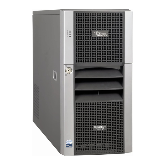
- Page 1 PRIMERGY TX200 S4 Server Service Supplement Edition December 2007...
-
Page 2: Copyright And Trademarks
Gesellschaft für Technik-Dokumentation mbH www.cognitas.de Copyright and Trademarks Copyright © 2007 Fujitsu Siemens Computers GmbH. All rights reserved. Delivery subject to availability; right of technical modifications reserved. All hardware and software names used are trademarks of their respective manufacturers. -
Page 3: Table Of Contents
Contents Introduction ......5 Overview of the documentation ....5 Notational conventions . - Page 4 Contents Replacing the chassis ID board ....36 4.10 Replacing the system board ....37 Appendix .
-
Page 5: Introduction
Introduction The PRIMERGY TX200 S4 Server is an Intel-based server for medium-sized and large networks. The server is suitable for use as a file server as well as an application, information, or Internet server. It is available as a floorstand or rack model (PRIMERGY Classic 19“... - Page 6 Overview of the documentation Introduction Information/procedure Manual Detailed safety notes “Safety notes and other important information” manual Features and technical data of the server Operating Manual Installation and operation, among other things: – External ports – Operation – Configuration of the server –...
- Page 7 Introduction Overview of the documentation Information/procedure Manual Extensions and upgrades: Options Guide For some components only the installation routine is described in the Options Guide. Removing these components proceed in reverse order. – Extending/replacing the main memory – Installing a second processor / replacing the processor / replacing the heat sink –...
-
Page 8: Notational Conventions
Notational conventions Introduction Notational conventions The following notational conventions are used in this manual: Text in italics indicates commands or menu items. „Quotation marks“ indicate names of chapters and terms that are being emphasized. Ê describes activities that must be performed in the order shown. -
Page 9: Procedure
Procedure CAUTION! The actions described in these instructions should only be performed by service personnel. Ê First of all please familiarize yourself with the safety instructions in the section chapter “Safety notes” on page 11 et seq. . Ê Ensure that all required manuals (see Service DVD) are available, printing out the PDF files if necessary. -
Page 11: Safety Notes
Safety notes The following safety notes are also provided in the “Safety notes and other important information” manual. This device complies with the relevant safety regulations for data processing equipment. CAUTION! The actions described in these instructions should only be performed by service personnel. - Page 12 Safety notes CAUTION! ● This device has a specially approved power cable and must only be connected to a grounded insulated socket (floorstand model) respec- tively to a safety socket on the rack mains socket strip (rack model). ● Ensure that the power socket on the device or the grounded wall outlet is freely accessible.
- Page 13 Safety notes CAUTION! ● Proper operation of the device (in accordance with IEC 60950-1/ EN 60950-1) is only ensured if the casing is completely assembled and the rear covers for the installation openings have been put in place (electric shock, cooling, fire protection, interference suppression).
- Page 14 Safety notes CAUTION! ● Replace the lithium battery on the system board in accordance with the instructions in the Technical Manual for the system board. All batteries containing pollutants are marked with a symbol (a ● crossed-out garbage can). In addition, the marking is provided with the chemical symbol of the heavy metal decisive for the classification as a pollutant: Cd Cadmium...
- Page 15 Safety notes ● Protect the CDs/DVDs from exposure to heat and direct sunlight. Laser information The CD/DVD drive complies with IEC 60825-1 laser class 1. CAUTION! The CD/DVD drive contains a light-emitting diode (LED), which under certain circumstances produces a laser beam stronger than laser class 1.
- Page 16 Safety notes ● Use a grounding cable designed for this purpose to connect yourself to the system unit as you install components. ● Place all components on a static-safe base. You will find a detailed description for handling ESD components in the relevant European or international standards (DIN EN 61340-5-1, ANSI/ESD S20.20).
-
Page 17: Replacement Routines
Replacement routines CAUTION! Observe the safety instructions in the chapter “Safety notes” on page 11 et seq. . Preparation You will find a detailed description of ’Opening the server’ and of the removing and installing the system fans and the traverse in the Options Guide TX200 S4. -
Page 18: Rack Model
Preparation Replacement routines 4.1.2 Rack model Ê Terminate all applications and shut down the server correctly. Ê If your operating system has not switched off the server, press the on/off button. Ê Pull all power connectors out of the power outlets. 4.1.2.1 Opening the server Ê... -
Page 19: System Fans And Traverse
Replacement routines Preparation 4.1.3 System fans and traverse 4.1.3.1 Removing the system fan 1 Ê Disconnect the fan cable from the connector FAN1 SYS on the system board. Ê Push the lock inward until it disengages. Ê Push the air duct to the front side until the pins on the PSU casing and the traverse disengage. -
Page 20: Replacing The Operating Panel Board
Replacing the operating panel board Replacement routines Replacing the operating panel board Ê Open the server and remove the front cover or the rack front cover as described in the section “Preparation” on page Ê Remove the system fan 1 as described in the section “Removing the system fan 1”... - Page 21 Replacement routines Replacing the operating panel board Figure 3: Releasing the lower hook Ê Press the lower hook upward (see the arrow). Figure 4: Pulling out the operating panel board with its holder Ê Pull the operating panel board out with its holder. Ê...
- Page 22 Replacing the operating panel board Replacement routines Figure 5: Taking the operating panel board out of its holder Ê Pull the sides of the holder apart and remove the operating panel board. Ê Insert the new operating panel board in the holder. Ê...
-
Page 23: Replacing The Front Usb Cable
Replacement routines Replacing the Front USB cable Replacing the Front USB cable Ê Open the server and remove the front cover or the rack front cover as described in the section “Preparation” on page Ê Remove the system fan 1 as described in the section “Removing the system fan 1”... -
Page 24: Replacing The Standard Ps
Replacing the standard PS Replacement routines Replacing the standard PS Ê Open the server as described in the section “Preparation” on page Ê Remove the system fan 1, the system fan 2 and the traverse as described in section “System fans and traverse” on page Ê... - Page 25 Replacement routines Replacing the standard PS Figure 8: Mounting the bracket onto the new power supply unit Ê Remove the mounting bracket from the defective power supply unit, and mount it onto the new power supply unit (two screws). Figure 9: Mounting bracket: centering tab Ê...
-
Page 26: Replacing The Power Backplane
Replacing the Power backplane Replacement routines Ê Thread the power cables which are used through the opening of the PS separation plate. All the rest of the power cables remain in the standard PS bay. Ê Connect all power cables to the system board and the drives (see the cabling plans in the Appendix of the Options Guide). - Page 27 Replacement routines Replacing the Power backplane Figure 10: Removing the PS safe guard CAUTION! Before removing the PS safe guard, the server must be disconnected to the main voltage because of energy hazard on the Power backplane. Ê Remove the screw (see the circle) and take out the PS safe guard. Take care that the screw doesn’t fall inside the housing.
- Page 28 Replacing the Power backplane Replacement routines Guides Figure 11: Removing the Power backplane Ê Remove the screw (see the circle). Ê Push the Power backplane in direction of the arrows until it gets out of the PS cage guides. Take out the Power backplane. Ê...
- Page 29 Replacement routines Replacing the Power backplane Ê Plug the power cables on the Xn connectors of the new Power backplane: Xn connector Cable designation T26139-Y3758-V5 / SNP:A3C40087908 T26139-Y3952-V2 / SNP:A3C40087920 T26139-Y3952-V101 / SNP:A3C40087920 Ê Install the PS safe guard and fasten it with one screw. Ê...
-
Page 30: Replacing The 3.5" Hdd Backplane
Replacing the 3.5“ HDD backplane Replacement routines Replacing the 3.5“ HDD backplane As spare part the 3.5“ HDD backplane is already mounted in the backplane holder. Ê Open the server as described in the section “Preparation” on page Ê Remove all the hot-plug hard disk drives (for a description see the Operating Manual). - Page 31 Replacement routines Replacing the 3.5“ HDD backplane Centering tabs Figure 13: Removing the screw Ê Remove the screw (see the circle). Ê Lift the backplane holder a little way and tilt it slightly away from the hard disk cage. Ê Lift the backplane holder up and off. Ê...
-
Page 32: Replacing The 2.5" Hdd Backplane
Replacing the 2.5“ HDD backplane Replacement routines Replacing the 2.5“ HDD backplane Two 2.5“ HDD backplanes are mounted on the hard disk cage. Ê Open the server as described in the section “Preparation” on page Ê Remove all the hot-plug hard disk drives (for a description see the Operating Manual). - Page 33 Replacement routines Replacing the 2.5“ HDD backplane Centering tabs Figure 15: Removing the screws Ê Remove the two screws (see the circles). Ê Lift the backplane a little way and tilt it slightly away from the hard disk cage. Ê Take the backplane out downward. Ê...
-
Page 34: Replacing The Intrusion Switches
Replacing the intrusion switches Replacement routines Replacing the intrusion switches In the floorstand model two intrusion detection switches monitor the removing of the left side cover and the hard disk cover. In the rack model only one intrusion switch is active, this one monitors the removing of the top cover. One switch is situated at the side (floorstand model) or the top (rack model) of the accessible drives, the other switch at the front cover over the hard disk cage. - Page 35 Replacement routines Replacing the intrusion switches Ê Thread the intrusion switch cable through the recess. Figure 17: Removing the intrusion switch 2 Ê Remove the two screws (see the arrows) and take out the intrusion switch inward. Ê Remove the intrusion switch cable from the connector on the system board (see also the Technical Manual of the system board).
-
Page 36: Replacing The Chassis Id Board
Replacing the chassis ID board Replacement routines Replacing the chassis ID board This board includes two important system components: – EEPROM for the chassis ID and ident number of the server – temperature sensor for monitoring the environment temperature The data for the EEPROM, and the current temperature values as well, are transmitted to the system board via the connected I C bus. -
Page 37: Replacing The System Board
After installing the new chassis ID board, it is necessary to program the Chassis ID prom with the help of the "Chassis ID Prom Tool" to enable ServerView and ServerStart to identify the system. The tool can be downloaded from the Fujitsu Siemens Computers Service and Support page (URL: http://extranet.fujitsu-siemens.com/service/information/intelservers/tools). - Page 38 Figure 19: Removing the screws Ê Remove the nine screws from the system board. Ê Lift the system board slightly using the socket of PCI slot 5, thereby you lift the system board out of the centre rings of the spacer bolts. Ê...
- Page 39 Replacement routines Replacing the system board Ê Adjust the system board with the help of the centering holes. If necessary adjust the position of the system board with a gentle twisting motion. CAUTION! Ensure that the holes of the spring plates are congruent to the standoff threads (see the red circles in the figure 19 on page 38).
-
Page 41: Appendix
Appendix Board layout The board layout of the system board is described in the Technical Manual of the system board D2509. 5.1.1 Operating panel board Part number: A3C40085518 operating panel cable Connector operating panel cable Service Supplement TX200 S4... -
Page 42: Hdd Backplane
Board layout Appendix 5.1.2 3.5“ HDD backplane Part number: A3C40086258 Connector power cable Connector SATA cable Service Supplement TX200 S4... -
Page 43: Hdd Backplane
Appendix Board layout 5.1.3 2.5“ HDD backplane Part number: A3C40086493 Connector SAS cable Connector power cable Service Supplement TX200 S4... -
Page 44: Power Backplane
Board layout Appendix 5.1.4 Power backplane Part number: A3C40087293 No. Xn connector Connector for cable T26139-Y3758-V5 / SNP:A3C40087908 T26139-Y3952-V2 / SNP:A3C40087920 T26139-Y3952-V101 / SNP:A3C40087920 Service Supplement TX200 S4... -
Page 45: Index
Index 2.5" HDD backplane 32, 3.5" HDD backplane 30, chassis ID board ESD (devices sensitive to electrostatic discharge) Front USB cable intrusion detection switches laser information light emitting diode (LED) lithium battery meaning of the symbols notational conventions operating panel board 20, Power backplane 26, standard PS system board... - Page 47 Copyright Fujitsu Technology Solutions, 2009 Hinweise zum vorliegenden Dokument Zum 1. April 2009 ist Fujitsu Siemens Computers in den alleinigen Besitz von Fujitsu übergegangen. Diese neue Tochtergesellschaft von Fujitsu trägt seit- dem den Namen Fujitsu Technology Solutions.
Need help?
Do you have a question about the PRIMERGY TX200 S4 and is the answer not in the manual?
Questions and answers