Fujitsu Siemens Computers PRIMERGY TX120 Options Manual
Fujitsu siemens computers server options guide
Hide thumbs
Also See for PRIMERGY TX120:
- Operating manual (82 pages) ,
- Price list (453 pages) ,
- Options manual (61 pages)
Table of Contents
Advertisement
Quick Links
Advertisement
Table of Contents

Subscribe to Our Youtube Channel
Related Manuals for Fujitsu Siemens Computers PRIMERGY TX120


Summary of Contents for Fujitsu Siemens Computers PRIMERGY TX120
- Page 1 PRIMERGY TX120 Server Options Guide Edition August 2007...
-
Page 2: Copyright And Trademarks
Gesellschaft für Technik-Dokumentation mbH www.cognitas.de Copyright and Trademarks Copyright © 2007 Fujitsu Siemens Computers GmbH. All rights are reserved. Delivery subject to availability. The right to technical modification is reserved. All hardware and software names used are trade names and/or trademarks of their respective... -
Page 3: Table Of Contents
Preparation ......19 Opening the server ..... . . 19 Removing the crosspiece . - Page 4 Installing the crosspiece ....43 Assembling the server ..... 44 Appendix .
-
Page 5: Introduction
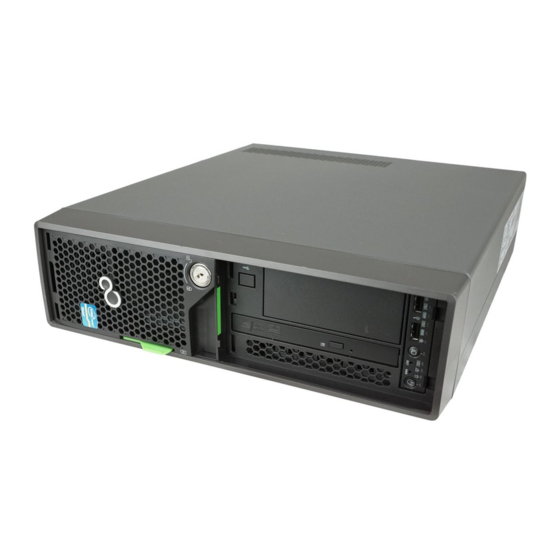
Introduction The PRIMERGY TX120 server is an Intel-based server for small and medium- sized networks and can be used in the horizontal position or as a desktop model. The PRIMERGY TX120 server features exceptionally low energy consumption, very quiet running and a compact size. As a result, it is also the ideal solution for home and small offices. -
Page 6: Documentation Overview
Documentation overview Documentation overview More information on your PRIMERGY TX120 can be found in the following documents: – “Quick Start Hardware - PRIMERGY TX120” (only included as a printed copy) – “Quick Start Software - Quick Installation Guide” (only included as a printed copy) –... - Page 7 The PRIMERGY server documentation can be accessed using the Industry standard servers navigation option. If you need a replacement copy of the ServerBooks DVD, send the details of your server to the following e-mail address: LOG@fujitsu-siemens.com Further sources of information: –...
-
Page 8: Expansions And Conversions
Expansions and conversions Expansions and conversions Main memory expansion The system board supports up to 8 Gbyte of main memory. 4 slots (2 memory banks with 2 slots each) are provided for the main memory. Each memory bank can be equippeded with 512 Mbyte, 1 Gbyte or 2 Gbyte unbuffered DDR2 memory modules. -
Page 9: Notational Conventions
Introduction Notational conventions The following notational conventions are used in this manual: Text in italics indicates commands, menu items or software programs. “Quotation marks” indicate names of chapters and terms that are being emphasized. Ê describes activities that must be performed in the order shown. -
Page 11: Procedure
The Operating Manual for the server describes how you install/remove the hot-plug components. Ê Close the server, connect it to the power outlet, and switch it on as described chapter “Completion” on page Ê Start the operating system and, if necessary, configure it as required (see the Operating Manual). -
Page 13: Safety
Safety The following safety instructions are also provided in the manual “Safety notes and other important information”. This device complies with the relevant safety regulations for data processing equipment. If you have any questions about where you can set up the device, contact your sales outlet or our customer service team. - Page 14 Safety Before starting up CAUTION! During installation and before operating the device, observe the instructions on environmental conditions for your device. If the device is brought in from a cold environment, condensation may form both inside and on the outside of the device. Wait until the device has acclimatized to room temperature and is absolutely dry before starting it up.
- Page 15 Always connect the server and the attached peripherals to the same power circuit. Otherwise you run the risk of losing data if, for. example, the server is still running but a peripheral device (e.g. memory subsystem) fails during a power outage.
- Page 16 Exception: hot-pluggable power supply units can be replaced. The warranty is void if the server is damaged during installation or replacement of system expansions. Only set screen resolutions and refresh rates that are specified in the operating manual for the monitor.
- Page 17 When working with devices with CD/DVD drives, these instructions must be followed. CAUTION! Only use CDs/DVDs that are in perfect condition in your server's CD/DVD drive, in order to prevent data loss, equipment damage and injury. Check each CD/DVD for damage, cracks, breakages etc. before inserting it in the drive.
- Page 18 Safety Modules with electrostatic-sensitive components Systems and components that might be damaged by electrostatic discharge (ESD) are marked with the following label: Figure 1: ESD label When you handle components fitted with ESDs, you must observe the following points under all circumstances: Remove the power plug before installing or removing components containing ESDs.
-
Page 19: Preparation
(1), if the server is operated in the vertical position. Ê Press and hold in the locks on both sides of the server (2), push the top cover forwards and lift it up and off (3). -
Page 20: Removing The Crosspiece
Removing the crosspiece Preparation Removing the crosspiece Figure 3: Removing the crosspiece Ê Pull the crosspiece out a little to the side (1). Ê Unhook the crosspiece on the left (2). Ê Carefully remove the crosspiece (3). Options Guide TX120... -
Page 21: Removing The Drive Cage
Preparation Removing the drive cage Figure 4: Disconnecting the cables Ê Disconnect the following cables from the SAS backplane (1-3) and from the CD/DVD drive (4-5): 1. Power cable 2. SAS data cable 3. SAS-LED cable 4. Power cable 5. IDE cable TX120 Removing the drive cage Options Guide... - Page 22 Removing the drive cage Preparation Figure 5: Removing the drive cage Ê Disengage the lock of the drive cage (1). Ê Pull out the drive cage in the direction of the arrow (2). Options Guide TX120...
-
Page 23: Main Memory
Main memory CAUTION! Please note the safety instructions in The system board supports up to 8 Gbyte of main memory. 4 slots (2 memory banks with 2 slots each) are provided for the main memory. Each memory bank can be equippeded with 512 Mbyte, 1 Gbyte or 2 Gbyte unbuffered DDR2 memory modules. - Page 24 Equipping rules – If the memory modules are installed in pairs, they must be identical (2-way interleaved mode). – Memory module capacity may be different for the various pairs: e.g. pair 2A/2B may be equipped with two 512 Mbyte memory modules, and pair 1A/1B may be equipped with two 1 Gbyte memory modules.
-
Page 25: Expanding/Replacing The Main Memory
Main memory Expanding/replacing the main memory Ê Open the server (see section Ê Remove the crosspiece (see section page 20). Removing a memory module Figure 7: Removing a memory module Ê Fold the assembly brackets outwards on both sides of the corresponding slot (1). - Page 26 Ê Install the crosspiece (see section Ê Close the server (see section Ê If necessary, place the server in the vertical position as described in the operating manual Ê Connect the system to the line voltage and switch it on.
-
Page 27: Accessible Drives
A 3.5-inch bay for an HDD extension box (with a maximum of two HDD modules) or a backup drive is available. Installing an HDD extension box Ê Open the server (see section Ê Remove the crosspiece (see section page 20). - Page 28 Installing an HDD extension box Accessible drives Figure 10: Fixing the rails on the HDD extension box Ê Fix the rails to the HDD extension box by inserting the pins on the rail in the corresponding holes in the HDD extension box. Options Guide TX120...
- Page 29 Accessible drives Figure 11: Installing an HDD extension box Ê Slide the HDD extension box into the slot. Ê Connect the SAS data cable to the HDD extension box (see cabling diagrams in the appendix). Ê Connect the power cable to the HDD extension box (see cabling diagrams in the appendix).
- Page 30 (regulations on electromagnetic compatibility) and fire protection. Ê Close the server (see section Ê If necessary, place the server in the vertical position as described in the operating manual Ê Connect the system to the line voltage and switch it on.
-
Page 31: Installing A Backup Drive
Accessible drives Installing a backup drive Ê Open the server (see section Ê Remove the crosspiece (see section page 20). Ê Remove the drive cage (see section Figure 13: Removing the protection shield from the 3.5-inch bay Ê Grasp the protection shield through the holes and pull it out in the direction of the arrow. - Page 32 Installing a backup drive Accessible drives Figure 14: Fixing the rails on the backup drive Ê Fix the rails on the backup drive by inserting the pins on the rails in the corre- sponding holes in the backup drive. Figure 15: Installing a backup drive Ê...
- Page 33 Accessible drives Installing a backup drive Figure 16: Unfastening the cable clamp Ê Unfasten the cable clamp. Options Guide TX120...
- Page 34 Installing a backup drive Figure 17: Connecting the USB and power cables to the backup drive Ê Plug the USB cable (1) and the power cable (2) into the backup drive (see cabling diagrams in the appendix). Ê Plug the other end of the USB cable into the system board (see cabling diagrams in the appendix).
- Page 35 Ê Close the server (see section Ê If necessary, place the server in the vertical position as described in the operating manual Ê Connect the system to the line voltage and switch it on.
-
Page 37: Expansion Cards In The Pci Slots
Expansion cards in the PCI slots CAUTION! Follow the safety instructions in chapter PCI slot overview Figure 19: PCI slots PCI slot Description PCI Express x1 slot (slot in x1 size) PCI Express x4 slot (slot in x8 size) PCI slot (32-bit/33MHz) TX120 “Safety”... -
Page 38: Installing An Expansion Card
Installing an expansion card Installing an expansion card Ê Open the server (see section Ê Please read the documentation supplied with the expansion card. Figure 20: Opening the lock and removing the slot cover Ê Press the lock together (1) and open it up (2). - Page 39 Expansion cards in the PCI slots Installing an expansion card Figure 21: Installing an expansion card Ê Push the expansion card as far as it will go into the slot on the system board. Ê Press the expansion card into the slot until you feel it click into place. Options Guide TX120...
- Page 40 Ê If necessary, connect the cable to the expansion card and the other compo- nents. Ê Close the server (see section Ê If necessary, place the server in the vertical position as described in the operating manual Ê Connect the system to the line voltage and switch it on.
-
Page 41: Completion
Completion CAUTION! Follow the safety instructions in chapter Installing the drive cage Figure 23: Installing the drive cage Ê Place the drive cage on the 3.5-inch bay (1), so that the four tabs in the housing (a) are positioned in the corresponding openings. Ê... - Page 42 Installing the drive cage Figure 24: Connecting the cables Ê Plug the power cable (1), the SAS data cable (2) and the SAS LED cable (3) into the SAS backplane (see cabling diagrams in the appendix). Ê Plug the power cable (4) and the IDE cable (5) into the CD/DVD drive (see cabling diagrams in the appendix).
-
Page 43: Installing The Crosspiece
Completion Installing the crosspiece Installing the crosspiece Figure 25: Installing the crosspiece Ê Hook the crosspiece on the left in place (1). Ê Press on the right side of the crosspiece (2) until you feel it click into place. Options Guide TX120... -
Page 44: Assembling The Server
Assembling the server Figure 26: Assembling the server Ê Place the top cover flat and straight on the server and push it as far as it will go in the direction of the arrow. Make sure that the locks on both sides of the server engage. -
Page 45: Appendix
Appendix Cabling The following table shows a cable overview: Part number Code number A3C40083117 A3C40083119 A3C40083120 A3C40083123 A3C40083128 A3C40085241 TX120 Name SAS-LED cable USB cable IDE cable Control panel cable (front panel) SAS cable SAS-LED cable Options Guide Length 250 mm 85 mm 185 mm 50 mm... - Page 46 Cabling Legend: Data SATA Power Adapter ATA 100 PRIMERGY TX120 / D2550 Overview Cabling Power cable E416-V50 1x2.5“ BPL & optical drive S26361-K1109-V***-*-12 Figure 27: Power cable: SAS backplane and CD/DVD drive <- P7 PSU E516-V50 Options Guide Appendix FAN2...
- Page 47 Appendix Legend: Data SATA Power Adapter ATA 100 PRIMERGY TX120 / D2550 Overview Cabling Power cable E416-V50 2x2.5“ BPL, optical drive S26361-K1109-V***-*-12 Figure 28: Power cable: 2 x SAS backplane and CD/DVD drive TX120 PSU E516-V50 Options Guide Cabling FAN2...
- Page 48 Cabling Legend: Data SATA Power Adapter ATA 100 PRIMERGY TX120 / D2550 Overview Cabling Power cable E416-V50 1x2.5“ BPL, optical drive & Tape S26361-K1109-V***-*-12 Figure 29: Power cable: SAS backplane, backup drive and CD/DVD drive <- P7 PSU E516-V50 Options Guide...
- Page 49 Appendix Legend: Data SATA Power Adapter ATA 100 PRIMERGY TX120 / D2550 Overview Cabling Data cable System with AdOn SAS controller FP, Int & FAN‘s S26361-K1109-V***-*-12 Figure 30: Cabling: fan, control panel (front panel) TX120 Options Guide Cabling FAN2 FRONTPANEL...
- Page 50 Legend: Data SATA Power Adapter ATA 100 PRIMERGY TX120 / D2550 Overview Cabling Data cable System with AdOn SAS controller 2.5“ back plane & opt. drive S26361-K1109-V***-*-12 Figure 31: Data and signal cable: SAS backplane and CD/DVD drive Options Guide...
- Page 51 Data SATA Power Adapter ATA 100 PRIMERGY TX120 / D2550 Overview Cabling Data cable System with AdOn SAS controller 2x 2.5“ back plane & opt. drive S26361-K1109-V***-*-12 Figure 32: Data and signal cable: 2 x SAS backplane and CD/DVD drive...
- Page 52 Data SATA Power Adapter ATA 100 PRIMERGY TX120 / D2550 Overview Cabling Data cable System with AdOn SAS controller 2.5“ back plane, opt. drive & TAPE S26361-K1109-V***-*-12 Figure 33: Data and signal cable: SAS backplane, backup drive and CD/DVD drive...
-
Page 53: Abbreviations
Abbreviations Alternating Current ANSI American National Standard Institute ASR&R Automatic Server Reconfiguration and Restart BIOS Basic Input-Output System Baseboard Management Controller Cache Coherency Compact Disk CD-ROM Compact Disk-Read Only Memory Cylinder Head Sector CMOS Complementary Metal Oxide Semiconductor Communication Central Processing Unit... - Page 54 Abbreviations DIMM Dual Inline Memory Module Dual Inline Package Direct Memory Access Desktop Management Interface Error Checking and Correcting Extended Capabilities Port EEPROM Electrically Erasable Programmable Read-Only Memory Elektrostatisch Gefährdete Bauteile Emergency Management Port Enhanced Parallel Port Elektromagnetische Verträglichkeit Front Panel Controller Field Replaceable Unit Front Side Bus Options Guide...
- Page 55 Global Array Manager Graphical User Interface Hard Disk Drive Hot-Swap Controller I²C Inter-Integrated Circuit Input/Output Intelligent Chassis Management Identification Integrated Drive Electronics IOOP Intelligent Organization of PCI iRMC integrated Remote Management Controller Interrupt Request Line Local Area Network Logical Block Address TX120 Options Guide Abbreviations...
- Page 56 Abbreviations Liquid Crystal Display Logical Unit Number Low-Voltage Differential SCSI LichtWellenLeiter Multi Mode Faser Manually Retention Latch Non Maskable Interrupt NVRAM Non Volatile Random Access Memory Operating System Peripheral Component Interconnect Prefailure Detection and Analyzing POST Power ON Self Test RAID Redundant Arrays of Independent Disks Random Access Memory...
- Page 57 Read-Only Memory RemoteView Service Board Real Time Clock RTDS Remote Test- und Diagnose-System SAF-TE SCSI Accessed Fault-Tolerance Enclosures Serial Attached SCSI SATA Serial ATA Single Bit Error Single Connector Attachment SCSI Small Computer System Interface Sensor Data Record SDRAM Synchronous Dynamic Random Access Memory System Event Log System Management Interrupt TX120...
- Page 58 Abbreviations System Setup Utility SVGA Super Video Graphics Adapter Universal Serial Bus Video Graphics Adapter Zero Channel RAID Options Guide TX120...
-
Page 59: Index
PCI expansion card, installing PCI slots, overview protection shield removing 27, saving 27, server assembling opening slot cover removing saving target group top cover fitting removing Options Guide...
Need help?
Do you have a question about the PRIMERGY TX120 and is the answer not in the manual?
Questions and answers