HIKVISION DS-7200HVI-ST Series User Manual
Ds-7200hvi-st series
Hide thumbs
Also See for DS-7200HVI-ST Series:
- User manual (101 pages) ,
- Quick operation manual (30 pages) ,
- Technical manual (13 pages)
Table of Contents
Advertisement
Quick Links
Advertisement
Table of Contents

Related Manuals for HIKVISION DS-7200HVI-ST Series


Summary of Contents for HIKVISION DS-7200HVI-ST Series
- Page 1 DS-7200HVI-ST Series DVR USER’S MANUAL Version 1.0 ...
- Page 2 Hikvision except where specifically permitted under US andinternational copyright law. The information in this document is subject to change without notice. Hikvision assumes no responsibility or liability for any errors or inaccuracies that may appear in this book.
-
Page 3: Preventive And Cautionary Tips
Preventive and Cautionary Tips Before connecting and operating your DVR, please be advised of the following tips: • Ensure unit is installed in a well-ventilated, dust-free environment. • Unit is designed for indoor use only. • Keep all liquids away from the DVR. •... -
Page 4: Table Of Contents
TABLE OF CONTENTS Contents C H A P T E R 1Introduction ...................... 7 1.1 Overview ............................. 8 1.1.1 Product Key Features ........................ 8 1.2 Connecting Your DVR ........................ 10 1.3 Operating Your DVR .......................... 11 1.3.1 Using the Front Panel Controls .................... 11 1.4 Using the IR Remote Control...................... 13 1.5 Using a USB Mouse ........................... 14 1.6 Using the Soft Keyboard ........................ 15 C H A P T E R 2 Getting Started ...................... 16 2.1 Starting and Shutting Down Your DVR .................... 16 2.2 Rebooting and Locking Your DVR ...................... 17 2.3 Setting Date & Time .......................... 17 2.4 Checking the Status of Your DVR ...................... 19 C H A P T E R 3 Live Feed ........................ 20 3.1 Watching a Live Feed ........................ 20 3.1.1 Understanding Live Feed Icons .................... 20 3.1.2Operating the Live Feed ...................... 21 3.2 Using the Display Menu ........................ 23 ... - Page 5 5.1 Playing Back a Recording ........................ 30 5.1.1 Understanding the Playback Interface .................. 30 5.2 Searching for Recorded Files ...................... 31 5.3 Playing Back Recorded Files ...................... 32 5.4 Playing Back Multiple Channels ...................... 33 C H A P T E R 6 Backup ........................ 33 6.1 Backing Up Video Clips ........................ 33 6.1.1 Selecting Video Clips ........................ 33 6.2 Backing Up Video Clips ........................ 34 6.3 Backing Up Recorded Files ........................ 35 C H A P T E R 7 System Configuration .................... 37 7.1 Configuring Network Settings ...................... 37 7.2 Managing User Accounts ........................ 38 7.2.1 Adding a New Remote/Local User ..................... 38 7.2.2 Deleting a User ........................... 39 7.2.3 Editing a User .......................... 40 7.2.4 Switch User .......................... 40 7.3 Configuring PTZ Cameras ........................ 40 7.3.1 Configuring Basic PTZ Settings .................... 41 7.4 Customizing PTZ Presets, Patterns and Patrols ................ 42 7.5 Configuring Alarms and Exceptions .................... 43 7.5.1 Setting Up Motion Detection ..................... 43 ...
- Page 6 9.1.1 Checking Disk Status ........................ 51 9.2 Formatting Disk .......................... 51 9.2.1 Enabling Disk Overwrite ...................... 52 9.3 Managing Files .......................... 52 9.3.1 Searching for Recorded Files ...................... 52 9.4 Locking and Unlocking Recorded Files .................... 54 C H A P T E R 1 0 DVR Management .................... 55 10.1 Managing System .......................... 55 10.1.1 Upgrading the System Firmware ..................... 55 10.1.2 Restoring Default Settings ....................... 55 10.2 Exporting & Importing Configuration ..................... 56 10.3 Viewing System Logs ........................ 57 10.4 Locking and Unlocking System Menus .................... 58 6 ...
-
Page 7: Chapter 1Introduction
C H A P T E R 1 Introduction 7 ... -
Page 8: Overview
1.1 Overview Thank you for your purchase of the DS‐7200HVI‐STSeries Digital Video Recorder (DVR). To getthe most out of your DVR, please read through this User’sManual thoroughly. Developed by Hikvision on the basis of the latest technology, DS‐7200HVI‐ST Series Digital Video Recorder combines the latest in advanced H.264 video encoding and decoding technologies delivering high performance rock‐solid reliability and longer recording times. DS‐7200HVI‐ST Digital Video Recorder can be used as a standalone video surveillance product, as well as to build up a powerful surveillance network making it is perfect for home or small business applications. Figure 1.DS-7204HVI-ST DVR Figure 2. DS-7208HVI-ST DVR Figure 3. DS-7216HVI-ST DVR 1.1.1 Product Key Features Compression PAL/NTSC adaptive video inputs. H.264 video compression with high reliability and superior definition. - Page 9 1/4-camera video live view, with the camera order adjustable. Group switch, manual switch and automatic cycle modes selectable for video live view, with the auto cycle period configurable. Digital zoom in live view mode. Shield of assigned channel for live view. Privacy masking capability.
-
Page 10: Connecting Your Dvr
Remote manual recording. Remote video image capture in JPEG format. Remote PTZ control. Voice talk and broadcast. Built-in WEB Server. Development Provision of SDK in Windows and Linux operating systems. Application software source code of Demo. Support and training service for application system development. 1.2 Connecting Your DVR You may follow the diagram below (Figure 4) in connecting your DVR to its peripherals. ... -
Page 11: Operating Your Dvr
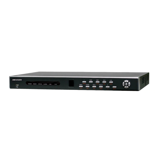
1.3 Operating Your DVR There are numerous ways to navigate and operate your DVR. You may use the FrontPanel Controls, the included IR (Infra-Red) Remote, a Mouse and the Soft-Keyboard. 1.3.1 Using the Front Panel Controls Your DVR comes with built‐in front panel controls, as shown in Figure 5. Figure 5. DVR Front Panel Controls The controls on the front panel includes: 1. Status Indicators: Status indicators for different features of the DVR. Power: Power indicator turns green when DVR is powered on. • Status: The indicator lights when the compound key switches to numeric/letter input mode. • TX/RX: TX/RX indictor blinks blue when network connection is functioning properly. • 2. IR Receiver: Receiver for IR remote. 3. Compound Buttons: 1 MENU: (1) Enter numeral “1”; (2) Enter the main menu interface •... - Page 12 ENTER Button: The ENTER button is used to confirm selection in any of the menu modes. It can also be used to • tick checkbox fields. In Playback mode, it can be used to play or pause the video. In Single Play mode, pressing the ENTER button will advance the video by a single frame. 6. USB Ports: Universal Serial Bus (USB) ports for additional devices such as USBmouse and USB Hard Disk Drive (HDD). Note: It is important to note that you must click the EDIT button on either the remote or front panel on a text field before you’re able to edit its content. After you’re done entering text, you must hit the ENTER button to be able to move on to the next field. Note : ...
-
Page 13: Using The Ir Remote Control
1.4 Using the IR Remote Control Your DVR may also be controlled with the included IR remote control, shown in Figure 6. Batteries (2x AAA) must be installed before operating. Figure 6. IR Remote Control 13 ... -
Page 14: Using A Usb Mouse
The keys on the remote control closely resemble the ones found on the front panel.Referring to Figure 6, they include: 1. POWER Button: Same as POWER button on front panel . 2. DEV Button: Enables/Disables Remote Control. 3. Alphanumeric Buttons: Same as Alphanumeric buttons on front panel . 4. EDIT Button: Same as EDIT/IRIS+ button on front panel . 5. A Button: Same as A/FOCUS+ button on front panel. 6. REC Button: Same as REC/SHOT button on front panel . 7. PLAY Button: Same as PLAY/AUTO button on front panel . 8. INFO Button: Same as ZOOM+ button on front panel . 9. VOIP Button: Same as MAIN/SPOT/ZOOM‐ button on front panel . 10. MENU Button: Same as MENU/WIPER button on front panel . 11. -
Page 15: Using The Soft Keyboard
1.6 Using the Soft Keyboard When a mouse is used to perform task on the DVR, clicking on a text input field will bringup the Soft Keyboard, shown in Figure 7. Figure 7. Soft Keyboard The buttons on the soft keyboard represents: Switch to Lowercase: Switch to lowercase input. Switch to Uppercase: Switch to uppercase input. Symbols: Switch to symbols input. Backspace: Delete the character in front of the cursor. Enter: Confirm selection. ESC: Exit out of Soft Keyboard. Figure 8. Soft Keyboard Buttons 15 ... - Page 16 C H A P T E R 2 2 tting S Starte 2.1 S Startin ng and d Shutt ting Do own Yo our DV VR Proper sta artup and shutdo own procedures s are crucial to e expanding the l life of your DV To startup p your DVR: Ensure the pow wer supply is plu ugged into an e electrical outlet.
-
Page 17: Rebooting And Locking Your Dvr
Select the Shutdown button. Click the Yes button. Note: 7216HVI‐ST support manual shutdown. Press and hold the power button for 3 seconds. Enter the administrator’s user name and password for authentication. Then click Yes button. 2.2 Rebooting and Locking Your DVR While in the Shutdown menu (Figure 10), you may also reboot or lock your DVR. Lockingyour DVR will return you to the Live Feed mode, which will require the correctadministrator password to exit out of it. The Reboot button will reboot your DVR. To reboot or lock your DVR: 1. Enter the Shutdown menu by going to Main Menu > Maintenance > Shutdown. 2. Select the Lock button to lock the DVR or the Reboot button to reboot the DVR. 2.3 Setting Date & Time It is extremely important to setup the system date and time to accurately timestamprecordings and events. To setup date and time: Enter the System Configuration menu by going to Main Menu > System Configuration,as shown in Figure 11. Figure 11. System Configuration Menu 17 ... - Page 18 Click the Time e/Date button t to enter the Ti ime/Date menu u (Figure 12). Figu ure 12. Time/Da ate Menu The current sy ystem time and d date as well a as the time zon ne will be disp layed.Using th e directional b buttons on the front panel/re emote or the m mouse, selectth e correct date, , time and time e zone. To enable Day ylight Savings T Time, click and d check the Ena able DST chec ckbox. To acquire the e time and date e over an NTP (Network Tim me Protocol) Se erver,check the...
- Page 19 2.4 C Checki ing the e Statu us of Y Your DV VR The curre ent status of yo our DVR can be e checked at an nytime by goin ng to the Status s menu. TheSta atus menu, sho own inFigure 14 can be e accessed by g going to Main M Menu > Status. igure 14. Status s Menu The items s that are foun d on the Status s menu include e: Model: The m model number o of the DVR. • rsion: The curr rent firmware version install led on the DVR R. ...
-
Page 20: Chapter 3 Live Feed
C H A P T E R 3 Live Feed 3.1 Watching a Live Feed The Live Feed mode is automatically started after the DVR boots up. It is also at the very topof the menu hierarchy, thus hitting the ESC button multiple times (depending on whichmenu you’re on) will bring you to the Live Feed mode. 3.1.1 Understanding Live Feed Icons There are multiple icons on each display in Live Feed mode to indicate different camerastatus and settings. These icons include: Event Icon: Indicates video loss or tampering, motion detection and/or sensor alarm. Record Icon: Indicates the current channel is recording. Therecording may have been started manually, from a schedule, and/ortriggered from motion or alarm. Picture Settings Icon: Adjust picture settings for selected display. PTZ Control Icon: Enter PTZ control mode for the selected display. Preset Icon: Recall PTZ preset. Patrol Icon: Recall PTZ patrol. Tour Icon: Recall PTZ tour. Zoom In/Zoom Out: Zoom in/out with PTZ. ... - Page 21 3.1.2O Operating the Live Feed In Live Fe eed mode, you may adjust the e settings for i ndividual cam meras by left‐cli icking onthe de esired display with the mouse. Th he selected dis splay will be su urrounded wit h a greenbord er, as shown in n Figure 16. gure 16. Live Fe eed Mode The settin ngs you may ad djust with each h display inclu des: Settings: Setti ings for the bri ightness, contr rast, saturation n and hue ofsel lected display.
- Page 22 ontrol: If the se elected camera a is a PTZ came era, you may c ontrol itdirect ly from the dis splay. To contr rol a PTZ • PTZ Co camera: Select display that correspon nds to a PTZ ca amera. Click the PTZ C Control icon. T This will bring up additional P PTZ control bu uttons,as show wn in Figure 18 8. Figur re 18. PTZ Con ntrol Mode Control the PT TZ using PTZ co ontrol buttons s. Pan and tilt P PTZ by clicking g onthe directio onal buttons. Z Zoom in and out using the Z Zoom In/Out b buttonsand rec...
-
Page 23: Using The Display Menu
3.2 Using the Display Menu The Display Menu can be accessed by right‐clicking the mouse on any of the display in Live Feed mode. The Display menu, shown in Figure 20 allows you to quickly change into different display modes and to start/stop auto‐switching of the display modes. Figure 20. Live Feed Display Menu 2x2 Mode: Click to switch to fourchannel display mode. 3x3 Mode: Click to switch to ninechannel display mode. 4x4 Mode: Click to switch to sixteenchannel display mode. Main Menu: Click to go to DVR MainMenu. If Lock Main Menu is selected inthe Lock Menus menu, you must enterthe current Admin Password to exit outof the Live Feed. 23 ... -
Page 24: Configuring Live Feed Displays
Start/Stop Auto-Switch: Click to start/stop auto‐switch. Auto‐switch will cyclethrough selected cameras. Switching ofcamera can be on an individual ormultiple camera basis. Next Set of Display: Click to view thenext set of display. In 2x2 mode, this willshow the next four display. In 3x3 mode,this will show the next nine display. Note: In order to use auto‐switching of channels, the dwell time must be configured inthe Display Configuration menu. Note: After 20 seconds of inactivity, the DVR will automatically exit out of the Displaymenu and go back into the Live Feed mode. Note: The Lock Main Menu setting is selected by default, meaning the Admin passwordmust be enter to exit out of the Live Feed into the Main Menu. To change this option andremove the lock to the Main Menu, visit the Lock Menus menu (See Locking andUnlocking System Menus on page 59). 3.3 Configuring Live Feed Displays Live Feed displays can be customized to your own needs. These settings can be accessedby entering the Display Configuration menu, shown in Figure 21. Figure 21. Display Configuration Menu To customize display settings: ... -
Page 25: Setting Camera Order
• Screen Configuration: Screen configuration of each video output. Youmay select between a 1x1, 2x2 or 4x4 configuration. • Sequencing Dwell Time: The time in seconds to dwell between switchingof channels when Start Sequence is selected in Live Feed. Selecting DisableSwitching will disable switching in Live Feed. • Enable Audio: Enables/disables audio output for the selected video output. • Output Format: Designates the video output standard. • Device Name/No.: Designates the device name and number of the currentunit. • VGA Resolution: Designates the resolution of main VGA display. • Mouse Pointer Speed: Pointer speed of the mouse, the higher theamount, the faster the mouse would move. 3.4 Setting Camera Order Setting the camera order allows you to logically position cameras for more efficientmonitoring of your own individual location. ... -
Page 26: Chapter 4 Record Settings
C H A P T E R 4 Record Settings 4.1 Configuring Settings for Recording There are multiple ways to setup your DVR for recording. They include setting up arecording schedule, triggering a recording by motion detection and/or a sensor alarm, andmanually starting the recording. 4.1.1 Configuring Recording Settings Before setting your DVR up for recording, certain settings should be configured first.These settings can be found in the Recording Configuration menu, shown in Figure 23. Figure 23. Recording Configuration Menu The first set of settings to configure in this menu is the recording quality settings. Toconfigure the recording quality settings: Enter the Recording Quality Settings menu by going to Main Menu > RecordingConfiguration > Recording Quality Settings. -
Page 27: Configuring A Quick Recording Schedule
Select the Encoding Parameters mode to configure. Either Continuous or OnEvent can be selected. Select the camera resolution in the Resolution drop down menu The optionsfor the camera resolution includes 4CIF,CIF and QCIF. Select the recording Frame Rate to use for the designated camera. A rate of25 all the way down to 1of a frame can be selected. -
Page 28: Configuring An Advanced Recording Schedule
Select the Save button to save the schedule settings and select Exit to return tothe previous menu. Select the Exit button without clicking Save will quitout of the menu without saving settings. Note: On Event recordings are recordings that are triggered from motion detection and/or from an external alarm (See Configuring Alarms and Exceptions on page 61). Note: If an event occurs during Continuous recording, the frame rate will automaticallyswitch to that set for Event recording. 4.1.3 Configuring an Advanced Recording Schedule ... - Page 29 Figure 27. Advanced Schedule Configuration Error Messages Select the Add button to add time frame to schedule. The newly added timeframe will appear in the schedule on the left, with the schedule parametersshown on the right. Continuous recordings are shown in blue on the schedulewhile event recordings are shown in yellow. An example of this can be seenin Figure 28. Figure 28. Advanced Schedule Configuration Example Repeat steps 4‐10 to setup additional time periods for the selected day. 10. Select the Save button to save the schedule settings and select Exit to return tothe previous menu. Selecting the Exit button without clicking Save will quitout of the menu without saving settings. Note: Creating a schedule in the Quick Schedule Configuration menu will also create aschedule in Advanced Schedule Configuration. The quick schedule will show up as a timeperiod in the Advanced Schedule Configuration. 29 ...
-
Page 30: Chapter 5 Playback
C H A P T E R 5 Playback 5.1 Playing Back a Recording Previously recorded files can be played back using the Playback Interface. You must firstsearch for recordings to play them back. 5.1.1 Understanding the Playback Interface It’s important to understand how to use the Playback Interface to efficiently navigatethrough recorded files. To access the Playback Interface, shown in Figure 29, go to MainMenu > Playback. Figure 29. Playback Interface Menu Some of the main features of the Playback Interface includes: Channel Selector: Select the channel to search for recordings on. • Calendar: Select the date to search for recordings on. • Timeline: Select the time to search for recordings on. • Preview: Shows a preview of the selected recording. • Playback Controls: Controls for playback of the selected recording. • Clip Backup Tools: Tools to backup clips from a recording. • Clip Playback Controls: Controls for playback of marked clip. •... -
Page 31: Searching For Recorded Files
5.2 Searching for Recorded Files The Playback Interface allows for easy searching of recorded files. To search for recordedfiles using the Playback Interface: Enter the Playback menu, shown in Figure 28 by going to Main Menu > Playback. Select the channel to search for recordings on. Select the date to search for recordings on using the calendar. The system dateis shown at the top of the calendar. You may change the month and year of thecalendar by clicking the left and right arrows next to the month and year.Dates with continuous recordings in the selected month and channel are displayed inlight blue, and dates are displayed in yellow when they are on event recording. Dates without recordings are dark gray. The active selecteddate is displayed in light gray, as shown in Figure 30. Figure 30. Playback Menu Example Click on the desired date that is highlighted in light blue to search for recordings.If recordings exist, the timeline will be filled with blue bars to designaterecorded files. The playback marker, indicated by a green vertical line willautomatically jump to the beginning of the earliest recordings for the selecteddate. The marker can be moved to any other location by clicking on thedesired position on the blue bars. Select the Play button in the Playback Controls to start playback of the recording. 31 ... -
Page 32: Playing Back Recorded Files
5.3 Playing Back Recorded Files After finding the recordings you would like to playback (See Searching for RecordedFiles on page 37), you may use the Playback Controls to navigate through the recording. The controls found under Playback Controls include: Play Button:Button to playback recording. Decrease Speed Button: Button to decrease play speed. Increase Speed Button : Button to increase play speed Enter/Exit Full-Screen Mode: Button to enter into and exit out of full-screen mode. Enable/Disable Audio:Button to enable and disable audio in playback mode. Figure 31. -
Page 33: Playing Back Multiple Channels
5.4 Playing Back Multiple Channels You may also playback recordings from multiple channels simultaneously. To playbackrecordings from multiple channels: 1. Search and select recording to playback in the Playback Interface. 2. Enter into Full‐Screen mode, shown in Figure 30 by clicking the Full‐Screenbutton. 3. In Full‐Screen mode, you may select additional channels to playback by clickingthe checkbox next to the desired camera in the Channel Selector panel. Playbackwill begin simultaneously on the selected channels. 4. You may stop playback on any of the channels by un‐checking the checkboxnext to the channel. Note: Up to4 channels can be played back at the same time. C H A P T E R 6 Backup 6.1 Backing Up Video Clips Video clips can be backed up to various devices, such as USB flash drives, USB HDDs or aDVD writer. 6.1.1 Selecting Video Clips Video clips can be selected for backup in the Playback Interface using the controls found inthe Mark Clip For Backup panel, shown in Figure 33. Figure 33. Mark Clip For Backup Controls The controls found in the Mark Clip For Backup panel includes: Start Clip Button: Mark the starting point for the video clip. ... -
Page 34: Backing Up Video Clips
To select video clips in the Playback Interface: Enter the Playback Interface, shown in Figure 34 by going to Main Menu >Playback. Figure 34. Playback Menu Search for the recorded files that you would like to select video clips from(See Searching for Recorded Files on page 35). Video clips can only beselected in single playback mode. Select the starting position of the video clip by clicking the desired location onthe blue recordings bar. Click the Start Clip button. Select the ending position of the video clip. Click the stop Clip button. The selected video clip time range will be shown at the bottom of the PlaybackInterface, as seen in Figure 35. Figure 35. Video Clip Time Range You may play the video clip using the Play Clip button or use the arrow keysshown next to the clip time range to progress through the video one second,minute or hour at a time. Click the Save Clip button to save clip to the DVR. Clip must be first saved tothe DVR before it can be backed up to an external USB storage device or to aDVD writer. Clicking the Clear Clip button will remove the video clip. 10. Repeat steps 2‐7 to select additional clips. If you would like to backup videoclips at this point, click the Backup button. Note: The Play Clip, Save Clip and Clear Clip buttons are not available unless a completedvideo clip is selected. A completed video clip has a start and end point marked by using theStart Clip and End Clip button. Note: The Start Clip button is not available when there is still a video clip that has notbeen saved or cleared. 6.2 Backing Up Video Clips After video clips have been selected in the Playback Interface (See Selecting Video Clipson page 46), you may back them up to an external USB storage device or DVD writer bygoing to the Backup menu. -
Page 35: Backing Up Recorded Files
Figure 36. Clips Backup Menu If video clips were successfully saved to the HDD using the Playback Interface,they will be listed under the Backup Clips heading on the left hand side of themenu. The camera number as well as the time range would be listed. Select the video clips you would like to backup by checking the checkbox nextto the desired clips. You may also click the Play icon to play and review theclip. Video clips can be deleted by selecting it and clicking the Remove buttonor by clicking the Remove All button to delete all clips. Connect at least one USB storage device to the DVR. If the device is compatiblewith the DVR, it will automatically be detected. Select the backup device fromthe Backup Device drop down menu. The Clips Selected, Required Space and Available Space will be displayed onthe Clips Backup menu. If the USB storage device has not been properly initializedand formatted, you may click on the Format button to do so. It isimportant to note that formatting will delete ALL data from the storage device. If the available space on the storage device is adequate, select the Backup buttonto begin backup of the selected clips. After clips have been backed up, you may click the Playback button to return tothe Playback Interface or the Done button to return to the previous menu. Note: Formatting a storage device will permanently delete all the files on that device. There is also NO WARNING MESSAGE after clicking the Format button to format thestorage device. Please proceed with caution and backup all critical data from the storagedevice before formatting. 6.3 Backing Up Recorded Files Not only can video clips be backed up, full recorded files can also be backed up to a storagemedium. To back up recorded files: Search for recorded files using the File Management menu (See Searchingfor Recorded Files on page 83). Select the files you would like to backup by checking the box next to the file.You may also check the All File box ... - Page 36 Figure 37. Files Backup Menu 4. In the Files Backup menu, connect a USB storage device and click the Refreshbutton. If the device is detected, a list of its file contents as well as the availablefree space will be shown. 5. You may delete files on the USB storage device to free up additional storagespace by clicking the Delete button on the selected file. You may also formatthe device by clicking the Format button. Formatting will remove ALL filesfrom the device. 6. When there is sufficient storage space for backup, click the Backup button. Abackup progress bar will be shown. 7. Click the OK button once backup has completed. 8. Click the Exit button to return to the File Management menu. 36 ...
-
Page 37: Chapter 7 System Configuration
C H A P T E R 7 System Configuration 7.1 Configuring Network Settings 7.1.1 Network configuration Network settings must be configured before you’re able to use your DVR over the network. To configure network settings: Enter the Network Configuration menu, shown in Figure 38 by going to MainMenu > System Configuration > Network Configuration. Figure 38. Network Settings Menu The current network settings are displayed on the right side of the menu. If you have a DHCP server running and would like your DVR to automaticallyobtain an IP address and other network settings from that server, check theDHCP checkbox. If you would like to configure your own settings, enter the settings for: IP Address: IP address you would like to use for your DVR. • Subnet Mask: Subnet Mask of network. • Default Gateway: IP address of your Gateway. Typically the IP address ofyour router. • DNS Server: The preferred and alternate Domain Name System (DNS)Server to be used with your DVR. • To enable Dynamic DNS (DDNS), check the DDNS checkbox. Dynamic DNSallows you to create a hostname and associate it to your IP address, makingaccess to your DVR over the internet easier. To configure DDNS: ... -
Page 38: Managing User Accounts
Figure 39. Test Connection Confirmation Select the Save button to save the network settings and select Exit to return tothe previous menu. Selecting the Exit button without clicking Save will quitout of the menu without saving settings. 7.1.2 Extended remote connection Extended remote connection is used for adding more network visitors with sub stream. Check “Extended remote connection” to enable this function. 7204HVI‐ST support up to 24 network visitors, six for each channel. 7208HVI‐ST support up to 48 network visitors. 7216HVI‐ST support up to 50 networks visitors. If you don’t enable this function, then 7208HVI‐ST/7216HVI‐ST only support up to 24 network visitors. You have no need of checking “Extended remote connection” when it is 7204HVI‐ST. 7.2 Managing User Accounts By default, DVR comes with two user accounts, the Administrator account and the Guest accounts. TheAdministrator user name is admin and the password is 12345. The default password forAdministrator should be changed right away for security reasons. The Administrator hasthe authority to add, delete or configure parameters for many of the system functions. The Guest accounts user name is guest without password. You can easily switch between accounts by click Login/Logout at the lower left corner of the main menu. 7.2.1 Adding a New Remote/Local User You may add up to 30 new users to your DVR. To add new users: Enter the User Settings menu, shown in Figure 40 by going to MainMenu > System Configuration > User Settings. 38 ... -
Page 39: Deleting A User
Figure 40 0. Remote User Settings Menu Under Users L List, click on Se elect this entry t to add new user Once a new en try has been sel lected, the field ds under Users w will become ed ditable.Enter the e information fo or Name,... -
Page 40: Editing A User
5. Click th he Done button n to exit menu. . 7.2.3 E Editing a a User To edit a user: 1. Enter t he User Setting gs menu, show wn in Figure 39 9 by going to M MainMenu > Sy stem Configur ation > User Se ettings 2. Select a a user to edit in n the Users Lis st panel. 3. Edit us er information n in the Users a and Remote Pe ermissions pan nel. Remoteper rmissions are d defined above in Adding a ote User on pa age 54. ... -
Page 41: Configuring Basic Ptz Settings
7.3.1 Configuring Basic PTZ Settings Settings for a PTZ camera must be configured before it can be used. Before proceeding,verify that the PTZ and RS-485 of the DVR are connected properly. To configure PTZ settings: Enter the PTZ Configuration menu, shown in Figure 42 by going to MainMenu > System Configuration > PTZ Configuration. -
Page 42: Customizing Ptz Presets, Patterns And Patrols
Select the camera to test in the camera drop down menu. Using the Directional buttons and other PTZ control buttons (Zoom In/Out,Focus In/Out, Iris In/Out), test the functionality of the PTZ camera. If PTZcamera and protocol supports it, you may also click the Auto-Scan button totest its function. -
Page 43: Setting Up Motion Detection
Enter the PTZ Configuration m menu, shown in n Figure 42 by g going to MainM Menu > System Configuration > PTZ Configuration. Select the On C Camera Settin ngs tab. Select a Patrol l Number to se et from the drop p down list. - Page 44 • Sound Au udio Warning: : DVR will soun nd an audio wa arning if motion n isdetected in th he designated r regions of the camera. • Pop-up Im mage on Monit tor: DVR will show an image e of what caused d themotion on the monitor.
-
Page 45: Configuring Exceptions
Figure 47. Trigger Actions Sub-Menu. Select the alarm input to configure in the Alarm Input No. drop down menuon the upper left of the menu. If all alarm inputs are to be configured with thesame settings, select Allfrom the list. Select the Trigger Action for the external alarm input device. Normal Open orNormal Close can be selected. Select the PTZ Actions (only if a PTZ camera is configured on the DVR) to runwhen the alarm input is triggered. Only one PTZ action can be selected peralarm input. Select the Actions to run when the alarm input is triggered. Multiple actionscan be selected per alarm input. The actions available includes: Sound Audio Warning: DVR will sound an audio warning if alarm is triggered. • Pop-up Image on Monitor: DVR will show the corresponding channelthat is associated with the trigger input. • Notify Surveillance Center: DVR will notify surveillance center whenalarm is triggered. •... -
Page 46: Configuring E-Mail Settings
Select the Exception Type to configure. The exception type includes: HDD Full: If selected, trigger action when HDD is full. • HDD Error: If selected, trigger action when errors on the HDD aredetected. • Network Failure: If selected, trigger action when a network failure isdetected. • IP Conflict: If selected, trigger action if an IP conflict is detected. • Illegal Login: If selected, trigger action when illegal logins are detected. • Video Exception: If selected, trigger action when an exception such as distortedvideo is detected. • Video Output Standard Mismatch: If selected, trigger action when videooutput standard does not match. • Select the Actions to take when the exception is detected. More than oneaction can be selected. The actions available includes: Sound Audio Warning: DVR will sound an audio warning if exception isdetected. •... - Page 47 PEG: Enabling g will attach a s small JPEG seg gment (duratio n can beset ne ext to the Attac ch JPEG • Attach JP checkbox x) to the out‐go oing e‐mail. SSL: Ena able Secure Soc ckets Layer (SS SL) for out‐goin ng e‐mail. • Enter To E-ma ail Address an nd click the Add d button. The e e‐mail address will beadded to the Recipien nts List. You may now test the e‐mail l settings by cl icking the Test t button or rem move ane‐mail address off th he Recipients List by selecti ng the recipien...
- Page 48 You may clear r a privacy zon e at any time b by clicking on t the correspond dingClear Zone e button or Cle ear All button to clear all zon nes. Select the Save e button to sav ve the privacy zones settings and select Exi it toreturn to th he previous m menu. Selecting the Exit button n without click king Savewill q quit out of the m menu without saving setting gs. 8.2 C Config guring Video o Tamp pering Detec ction Video tam mpering detectio on can be used t to recognize if an area of a cam mera is purpose...
-
Page 49: Configuring Osd Settings
Figure 52. Video Loss Detection Menu Select the camera to setup video loss detection in using the camera drop downmenu on the upper left of the menu. If all cameras are to be configured withthe same settings, select All Cameras from the list. Click Enable Video Loss Detection. - Page 50 Figure 5 53. OSD Config uration Menu Select the came era to setup OS SD configuration n in using the c camera drop dow wnmenu on the e upper left of th he menu. If all cameras are to be configured w withthe same se ettings, select A All Cameras fro...
-
Page 51: Chapter 9 Disk Management
C H A P T E R 9 Disk Management 9.1 Managing Disks 9.1.1 Checking Disk Status The status of all installed hard disk drives (HDD) can be checked under the DiskManagement menu. To check the status of installed disks: Enter the Disk Management menu, shown in Figure 54 by going to Main Menu> System Configuration > Disk Management. Figure 54. Disk Management Menu There are four different panels found in the Disk Management menu. Theyinclude: Disk Utilization: Displays the maximum space available of all disks combined. • Available Disks: Displays a list of all installed disks(include local and network) and their respectivespace • and status. Status: Displays the available disk space of all disks combined. • Click the Done button to exit out of Disk Management. 9.2 Formatting Disk A newly installed hard disk drive (HDD) must be first formatted before it can be used withyour DVR. Formatting the disk will erase all data on it. To format a new disk: Enter the Disk Management menu, shown in Figure 54 by going to Main Menu> System Configuration > Disk Management. Select a disk to format. A disk that has not been formatted will show ErrorDetected as its status. If the disk is one that is newly installed, the status of thedrive will show up as Non-Active and the Reformat button will change to theAdd button. -
Page 52: Enabling Disk Overwrite
Figure 55. Disk Format Confirmation A format progress bar (Figure 55) will be shown on the menu. After the diskhas been formatted, the status of the disk will change to Active. Figure 55. Disk Format Progress Bar Click the Done button to exit out of Disk Management. 9.2.1 Enabling Disk Overwrite Enabling disk overwrite will allow the DVR to overwrite the installed disks once the disksare full. To enable disk overwrite: Enter the Disk Management menu, shown in Figure 54 by going to Main Menu> System Configuration > Disk Management. - Page 53 Figu ure 56. File Sear rch Menu Select the came eras that you w would like to inc clude in the sear rch. Analog cam merasare listed on the first row w, preceded with the letter A A. Digital came eras arelisted on n the second row w, preceded wi...
-
Page 54: Locking And Unlocking Recorded Files
9.4 Locking and Unlocking Recorded Files To lock and unlock recorded files: Search for recorded files using the File Management menu (See Searchingfor Recorded Files on page 83). Select the file you would like to lock/unlock. Click the Lock icon for the selected file. Click the Done button to exit out of the File Management menu. Note: Locked files will never be overwritten until they are unlocked. ... -
Page 55: Chapter 1 0 Dvr Management
C H A P T E R 1 0 DVR Management 10.1 Managing System 10.1.1 Upgrading the System Firmware The system firmware for your DVR can be updated from a USB storage device. To update the system firmware: Enter the Firmware Upgrade menu, shown in Figure 58 by going to MainMenu > Maintenance > Firmware Upgrade. Figure 58. Firmware Upgrade Menu Connect the USB storage device to a USB port on the DVR. Click the Refresh button. The contents of the USB storage device will be shownon the screen. Select the firmware file. The firmware file is named digicap. Click the Upgrade button to upgrade the DVR. The DVR will automaticallyreboot after the upgrade is completed. If you do not wish to upgrade at thispoint, click the Cancel button. 10.1.2 Restoring Default Settings To restore factory default settings to your DVR: Enter the Factory Default menu, shown in Figure 59 by going to Main Menu >Maintenance > Factory Default. 55 ... -
Page 56: Exporting & Importing Configuration
Figure 59. Factory Default Menu Select the OK button to restore factory defaults or select the Cancel button toreturn to the previous menu. Note: Network information such as IP address, subnet mask and gateway will not berestored. 10.2 Exporting & Importing Configuration Configuration information from your DVR can be exported to a USB storage device andimported into another DVR. This will allow you to efficiently setup the same configurationon numerous DVRs. -
Page 57: Viewing System Logs
Enter the Export/Import Configuration menu, shown in Figure 65 by going toMain Menu > Maintenance >Export/Import Configuration. Connect the USB storage device to a USB port on the DVR. Click the Refresh button. The contents of the USB storage device will be shownon the screen. Select the configuration file. -
Page 58: Locking And Unlocking System Menus
Select an entry to view more detail information about the entry. If applicable, you may also view the associated video to the selected log entryby clicking the Play button. Log files can also be exported onto a USB storage device. To export a log file,connect a USB storage device to the DVR, select the log files to export and clickthe Export button.
Need help?
Do you have a question about the DS-7200HVI-ST Series and is the answer not in the manual?
Questions and answers