
Related Manuals for Xantrex XHR 7.5-130


Summary of Contents for Xantrex XHR 7.5-130
- Page 1 XHR 7.5-130 XHR 20-50 XHR 33-33 XHR 40-25 XHR 60-18 XHR 100-10 XHR 150-7 XHR 300-3.5 XHR 600-1.7 Operating Manual XHR 1000 Watt Series Programmable DC Power Supply...
- Page 3 Operating Manual for XHR Series Programmable DC Power Supply...
- Page 4 What does this warranty cover and how long does it last? Warranty This Limited Warranty is provided by Xantrex Technology, Inc. (“Xantrex”) and covers defects in workmanship and materials in your XHR 1000 Watt Series DC Power Supply. This warranty lasts for a Warranty Period of 5 years from the date of purchase at point of sale to you, the original end user customer.
- Page 5 Direct returns may be performed according to the Xantrex Return Material Authorization Policy described in your product manual. For some products, Xantrex maintains a network of regional Authorized Service Centers. Call Xantrex or check our website to see if your product can be repaired at one of these facilities. In any warranty claim, dated proof of purchase must accompany the product and the product must not have been disassembled or modified without prior written authorization by Xantrex.
- Page 6 Disclaimer Product THIS LIMITED WARRANTY IS THE SOLE AND EXCLUSIVE WARRANTY PROVIDED BY XANTREX IN CONNECTION WITH YOUR XANTREX PRODUCT AND IS, WHERE PERMITTED BY LAW, IN LIEU OF ALL OTHER WARRANTIES, CONDITIONS, GUARANTEES, REPRESENTATIONS, OBLIGATIONS AND LIABILITIES, EXPRESS OR IMPLIED, STATUTORY OR OTHERWISE IN CONNECTION WITH THE PRODUCT, HOWEVER ARISING (WHETHER BY CONTRACT, TORT, NEGLIGENCE, PRINCIPLES OF MANUFACTURER’S LIABILITY, OPERATION OF LAW, CONDUCT, STATEMENT OR OTHERWISE), INCLUDING WITHOUT RESTRICTION ANY IMPLIED WARRANTY...
- Page 7 Please record the following information when you first open your Power Supply About Your package: Power Model Number ______________________________________________ Supply Serial Number ______________________________________________ Purchased From ______________________________________________ Purchase Date ______________________________________________ Release Revision A (2004-03) © Copyright 2004 Xantrex Technology Inc. All rights reserved. Printed in Canada Revision A...
- Page 8 Warnings Warnings and cautions are defined and formatted in this manual as shown below. Cautions WARNING Describes a potential hazard which could result in injury or death, or, a procedure which, if not performed correctly, could result in injury or death. CAUTION Describes a procedure which, if not performed correctly, could result in damage to data, equipment, or systems.
-
Page 9: About This Manual
About This Manual This Operating Manual contains user information for the Series DC output power supply, available in several models at 1000 watts. It provides information on features and specifications, installation procedures, and basic functions testing, as well as procedures for operating the power supply at the front panel or from a remote device. - Page 10 About This Manual Power Supply Safety Markings Alternating Current Off (Supply) Earth (Ground) Terminal Caution (Hot Surface) Protective Conductor Terminal Caution (Check manual additional information.) On (Supply) viii Operating Manual for XHR Series Power Supply...
-
Page 11: Table Of Contents
Contents About This Manual ........... vii List of Figures . - Page 12 Local and Remote Sensing ..........48 Sense Wiring .
-
Page 13: List Of Figures
List of Figures Figure 1.1 Power Supply Front Panel ....... . 17 Figure 1.2 Rear Panel with Bus Bar. - Page 14 List of Figures Operating Manual for XHR Series Power Supply...
-
Page 15: List Of Tables
List of Tables Table 1.1 SW1 Switch Functions ........20 Table 1.2 Electrical Specifications for 7.5 V to 40 V Models . - Page 16 List of Tables Operating Manual for XHR Series Power Supply...
-
Page 17: Description
Section 1. Features and Specifications Description The 1000 watt DC output power supplies provide low noise, precisely regulated, variable DC output. Typically they are used for bench and automated test equipment (ATE) applications. Each unit includes over voltage protection and thermal shutdown as standard features. -
Page 18: Front Panel Controls
Features and Specifications Front Panel Controls Remote analog voltage and current limit programming with selectable • programming ranges. External monitor signals for output voltage and current. • Isolated analog remote programming control of the output voltage or current and • isolated readback of output voltage and current with the optional ISOL interface. -
Page 19: Figure 1.1 Power Supply Front Panel
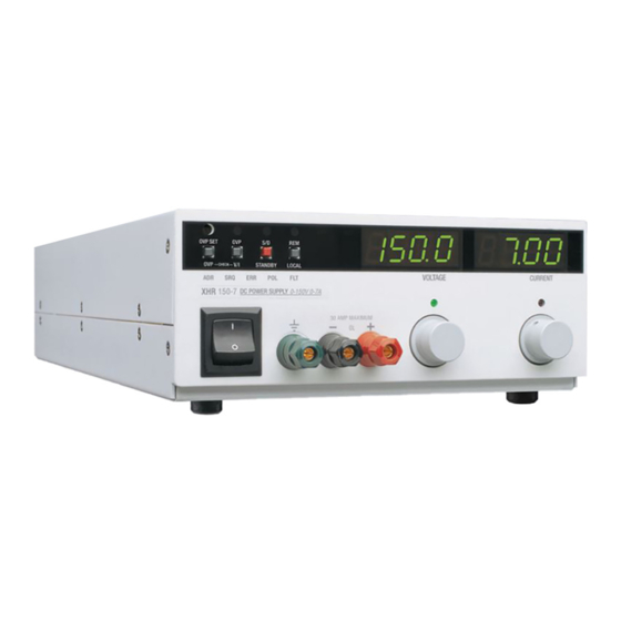
Features and Specifications Front Panel Controls Shutdown LED (S/D) (See page 61 for more information.) OVP Shutdown Standby Switch (STANDBY) LED (OVP) (See page 61.) Local Voltage and Current Remote Programming LED (REM) Limit Setting Preview Switch (See page 67.) (V/I CHECK) (See page... -
Page 20: Rear Panel Connectors And Switch
Features and Specifications Rear Panel Connectors and Switch Rear Panel Connectors and Switch The output terminals for the low voltage models (7.5 V to 40 V) are bus bars. The high voltage models (60 V to 600 V) use a wire clamp connector. See Figure 1.2 Figure 1.3 to identify the switches and connectors on the rear panel. -
Page 21: Sw1 Programming Switch
Features and Specifications Rear Panel Connectors and Switch 100/120/200/240V 50/60 HZ 1300VA Local Sense Wires DC Output and Local Sense Connector (See page 48.) (See page 39 for more information.) Figure 1.3 Rear Panel with High Voltage Output Connector (For 60 V to 600 V models.) The SW1 Programming, Monitoring, and Shutdown Select switch is an 8-position piano DIP switch located on the power supply’s rear panel. -
Page 22: J2 Programming Connector
Features and Specifications Rear Panel Connectors and Switch Table 1.1 for a list of the functions assigned to each SW1 switch. Table 1.1 SW1 Switch Functions Switch Function OFF (Open) ON (Closed) SW1-1 1 mA current source for resistive Voltage source Resistive programming of output voltage. -
Page 23: Figure 1.5 J2 Programming Connector
Features and Specifications Rear Panel Connectors and Switch Figure 1.5 to identify the function of each of the 12 terminals on the J2 connector. Wire Clamp Return Sense (–SNS) Connector Screw Positive Sense (+SNS) Control Ground ( Remote Output Voltage Programming Select (VRMT) Remote Current Limit Programming Select (IRMT) Program/Monitor Signal Return (PGM–) Output Voltage Programming Input (VPGM) - Page 24 Features and Specifications Rear Panel Connectors and Switch Wiring WARNING There is a potential shock hazard at the output and J2 terminals when using a power supply with a rated output greater than 40 V. Use load wiring with a minimum insulation rating equivalent to the maximum output voltage of the power supply.
-
Page 25: Specifications
Features and Specifications Specifications Specifications Electrical Specifications are warranted over a temperature range of 0 to 40 °C with default Specifications local sensing. The tables on the following pages post maximum values for model-dependent specifications. Specifications which are different due to measurements being taken at the front panel binding posts are identified, where they occur, in the tables. -
Page 26: Table 1.2 Electrical Specifications For 7.5 V To 40 V Models
Features and Specifications Specifications Table 1.2 Electrical Specifications 7.5 V to 40 V Models Models 7.5-130 20-50 33-33 40-25 Output Ratings: Output Voltage 0-7.5 V 0-20 V 0-33 V 0-40 V Output Current 0-130 A 0-50 A 0-33 A 0-25 A Output Power 975 W 1000 W... - Page 27 Features and Specifications Specifications Table 1.3 Electrical Specifications 60 V to 600 V Models Models 60-18 100-10 150-7 300-3.5 600-1.7 Output Ratings: Output Voltage 0-60 V 0-100 V 0-150 V 0-300 V 0-600 V Output Current 0-18 A 0-10 A 0-7 A 0-3.5 A 0-1.7 A...
-
Page 28: Additional Electrical Specifications
Features and Specifications Additional Electrical Specifications Additional Electrical Specifications Voltage Mode Transient Response 1 ms (Time for the output voltage to recover within 0.5% of its previous level after a step change in load current of up to 50% of the rated output.) Time delay from power on until 4 s maximum... -
Page 29: Electrical Characteristics
Features and Specifications Electrical Characteristics Electrical Characteristics Switching Frequency 7.5 V to 300 V models: nominal 125 kHz (250 kHz output ripple) 600 V model nominal 62.5 kHz (125 kHz output ripple) Output Hold-up Time Greater than 10 ms with interruption of AC line, for nominal AC input and full load. -
Page 30: Environmental Specifications
Features and Specifications Environmental Specifications Environmental Specifications Operating Ambient Temperature 0 to 40 °C. Storage Temperature Range – 40 ° to 85 °C Humidity Range Up to 80% RH, non-condensing Operating Altitude Up to 6,500 feet (2000 m) Installation Category Pollution Degree Approvals Units marked with c(CSA)us are CSA certified to:... -
Page 31: Mechanical Specifications
Features and Specifications Mechanical Specifications Mechanical Specifications Front Panel Voltage and Current 10-turn voltage and current potentiometers Control Front Panel Voltage Control 0.02% of maximum voltage Resolution Front Panel Voltage and Current 3.5-digit numeric LED displays (for accuracy Meters specifications, see Table 1.2 Table 1.3) -
Page 32: Dimensions
Features and Specifications Dimensions Dimensions 18.78 in. (477 mm) 15.85 in. (403 mm) 16.18 in. (411 mm) 8.45 in. (215 mm) 3.43 in. 3.14 in. (87 mm) (79 mm) Figure 1.6 Dimensional Drawings (Dimensions given are nominal.) Operating Manual for XHR Series Power Supply... -
Page 33: Basic Setup Procedure
Section 2. Installation Basic Setup Procedure Table 2.1 for a summary of the basic setup procedure and an overall view of the information in this section. Use the procedure as a quick reference if you are familiar with the installation requirements for the power supply. If you want more information, each step in the procedure refers to sections which contain more details. -
Page 34: Inspection, Cleaning, And Packing
Installation Inspection, Cleaning, and Packing Inspection, Cleaning, and Packing Initial When you first receive your unit, perform a quick physical check. Inspection 1. Ensure that each package contains the power supply and an AC input cord. 2. Inspect the unit for scratches and cracks, and for broken switches, connectors, and displays. -
Page 35: Returning Power Supplies To The Manufacturer
This warranty will not apply where the product is damaged due to improper packaging. 2. Include the following: The RMA number supplied by Xantrex Technology Inc clearly marked on • the outside of the box. -
Page 36: Packaging For Shipping Or Storage
Installation Returning Power Supplies to the Manufacturer Packaging for Follow these instructions to prepare the unit for shipping or storage. Shipping or 1. When returning the unit or sending it to the service center, attach a tag to the unit Storage stating its model number (available from the front panel label) and its serial number (available from the rear panel label). -
Page 37: Location, Mounting, And Ventilation
Installation Location, Mounting, and Ventilation Location, Mounting, and Ventilation Rack Mounting CAUTION Ensure that any rack mounting screws do not extend more than 1/4in. (6.3 mm) into the base of the unit. The rack mount kit allows you to mount two units side by side in a standard 19in. (483 mm) rack space. -
Page 38: Ac Input Power
Installation AC Input Power AC Input Power WARNING There is a potential shock hazard if the power supply chassis and cover are not connected to an electrical ground via the safety ground in the AC input connector. Ensure that the power supply is connected to a grounded AC outlet with the recommended AC input connector configured for the available line voltage CAUTION... -
Page 39: Functional Tests
Installation Functional Tests Functional Tests The functional test procedures include power-on and front panel function checks as well as voltage and current mode operation checks. Equipment Digital voltmeter (DVM) rated better than 0.5% accuracy. • Required DC shunt 1 mV/A (±0.25%) with connecting wire. The recommended current •... -
Page 40: Current Mode Operation Check
Installation Functional Tests Current Mode 1. Ensure that the front panel power switch is set to OFF. Operation 2. Turn the voltage and current controls on the front panel fully counter-clockwise. Check 3. Turn the voltage control one (1) or two (2) turns clockwise. 4. -
Page 41: Load Connection
Installation Load Connection Load Connection This section provides recommendations for load wires and how to connect them for both single and multiple load configurations. Load Wiring When connecting load wiring to the power supply, consider the following factors: Current capacity and voltage rating of the wire •... -
Page 42: Figure 2.2 Maximum Load Wire Length For 1 V Line Drop
Installation Load Connection Load Wiring Length for Operation with Sense Lines For applications using remote sensing, you must limit the voltage drop across each load line. Figure 2.2 shows some maximum allowable wire lengths for a given load current and wire size. We recommend that you use the larger load wiring to ensure a smaller voltage drop (1 V typical maximum), although the units (except 7.5 V models) will compensate for up to 5 V drop in each line. -
Page 43: Making Load Connections
Installation Load Connection Making Load Connections WARNING There is a potential shock hazard at the load when using a power supply with a rated output greater than 40 V. To protect personnel against accidental contact with hazardous voltages, ensure that the load, including connections, has no live parts which are accessible. -
Page 44: Inductive Loads
Installation Load Connection Shield Flat Washer (3 places) 1/4in. Screw (2 places) A16 EMI Filter Bus Bar Capacitor 3/8in. Screw (1 place) Figure 2.3 Bus Bar Shield Inductive Use the following protection methods only when using local sensing. Loads To prevent damage to the power supply from inductive kickback, connect a diode across the output. -
Page 45: Figure 2.4 Typical Load Connection Hardware
Installation Load Connection Wire Terminal Lug (2 places) Screw (2 places) Lock Washer (2 places) Hex Nut (2 places) Figure 2.4 Typical Load Connection Hardware (For 7.5 V to 40 V models.) To make load connections to a 7.5 V, 130 A power supply: 1. -
Page 46: Figure 2.5 Output Connector
Installation Load Connection 60 V to 600 V Models WARNING To protect personnel against accidental contact with hazardous voltages, ensure that the load, including connections, has no live parts which are accessible. Also ensure that the insulation rating of the load wiring and circuitry is greater than or equal to the maximum output voltage of the power supply. -
Page 47: Connecting Single Loads
Installation Load Connection Connecting Figure 2.6 Figure 2.7 show recommended load and sensing connections for single loads. Local sense lines shown are default J2 connections. Single Loads You do not need remote sensing for basic operation of your supply. However, if you wish to correct for any small drops in your load lines, then use this feature. -
Page 48: Figure 2.8 Multiple Loads With Local Sensing
Installation Load Connection Radial Power Distribution Method To connect distributed loads, we recommend that you use radial power distribution. With this method, you connect power to each load individually from a single pair of terminals designated as the positive and negative distribution terminals. These terminals may be the power supply output terminals, the terminals of one of the loads, or a distinct set of terminals especially established for distribution use. -
Page 49: Figure 2.9 Multiple Loads With Remote Sensing
Installation Load Connection Figure 2.9 Multiple Loads with Remote Sensing Revision A... -
Page 50: Local And Remote Sensing
Installation Local and Remote Sensing Local and Remote Sensing Use connections on the rear panel J2 connector to set up the power supply for local or remote sensing of output voltage. Sense Wiring WARNING There is a potential shock hazard at the sense connector when using a power supply with a rated output greater than 40 V. - Page 51 Installation Local and Remote Sensing Use remote sensing during voltage mode operation to shift the power supply’s regulation point from its output terminals to the load or distribution terminals by using a separate pair of wires to allow the control circuitry to monitor the load voltage.
-
Page 52: Figure 2.10Connecting Remote Sense Lines
Installation Local and Remote Sensing Figure 2.10Connecting Remote Sense Lines Operating Manual for XHR Series Power Supply... -
Page 53: Standard Operation
Section 3. Local Operation Standard Operation Once you have installed the power supply and as covered in Section 2. Installation, the power supply is ready to operate in local control mode (that is, operation at the front panel). The power supply has two basic operating modes: Constant Voltage Mode and Constant Current Mode, and two control modes: Local Control Mode (default setting) and Remote Programming Mode. -
Page 54: Figure 3.1 Operating Modes
Local Operation Standard Operation Output Voltage > Constant Voltage Mode Region Crossover Point V SET < Constant Current Mode Region Where: = Load Resistance = Output Voltage Setting Output Current = Output Current Setting I SET Figure 3.1 Operating Modes Constant Voltage Mode Operation The power supply will operate in constant voltage mode whenever the load current I is less than the current limit setting I... -
Page 55: Shipped Configuration (Local Control Mode)
Local Operation Standard Operation Shipped The factory ships units already configured for local control (front panel) operation. Configuration Table 3.1 summarizes this configuration. (Local Control Table 3.1 Shipped Configuration (Local Control Mode) Mode) Local Control Configuration Additional References Use the front panel controls to adjust the Section 3 covers front panel output voltage and current limit settings. -
Page 56: Using Multiple Supplies
Local Operation Using Multiple Supplies Using Multiple Supplies WARNING There is a shock hazard at the load when using a power supply with a rated or combined output greater than 40 V. To protect personnel against accidental contact with hazardous voltages created by series connection, ensure that the load, including connections, has no live parts which are accessible. -
Page 57: Configuring Multiple Supplies For Series Operation
Local Operation Using Multiple Supplies Configuring Multiple Supplies for Series Operation CAUTION Do not use remote sensing during series operation. CAUTION The maximum allowable sum of the output voltages is 600 Vdc. Use series operation to obtain a single higher voltage output using two or more supplies. -
Page 58: Configuring Multiple Supplies For Parallel Operation
Local Operation Using Multiple Supplies Configuring Use parallel operation to obtain a higher current through a single output using two or more supplies. Set all of the OVP set points to maximum. Set all of the outputs to the Multiple same voltage before connecting the positive (+) output terminals and negative (–) Supplies for output terminals in parallel. -
Page 59: Configuring Multiple Supplies For Split Supply Operation
Local Operation Using Multiple Supplies Configuring Split supply operation uses two power supplies to obtain two positive voltages with a common ground, or to obtain a positive-negative supply. Multiple Supplies for Split Supply Two Positive Voltages To obtain two positive voltages, connect the negative output terminals of both supplies together in a common connection. -
Page 60: Figure 3.5 Split Supply Operation Of Multiple Supplies
Local Operation Using Multiple Supplies Positive-negative Supply CAUTION To prevent possible damage to the supply, do not connect the remote program return line of the negative supply to the common connection. To obtain a positive-negative supply, connect the negative output terminal of one supply to the positive output terminal of the second supply. -
Page 61: Using Over Voltage Protection (Ovp)
Local Operation Using Over Voltage Protection (OVP) Using Over Voltage Protection (OVP) The OVP circuit protects the load in the event of a remote programming error, an incorrect voltage control adjustment, or a power supply failure. The protection circuit monitors the output voltage and will shut down the main power converter whenever a preset voltage limit is exceeded. -
Page 62: Resetting The Ovp Circuit
Local Operation Using Over Voltage Protection (OVP) Resetting the To reset the OVP circuit after it activates: OVP Circuit 1. Reduce the power supply’s output voltage setting to below the OVP set point. 2. Press the STANDBY switch IN. The S/D (Shutdown) LED on the front panel will turn on. -
Page 63: Using The Shutdown Function
Local Operation Using the Shutdown Function Using the Shutdown Function Use the Shutdown function to disable or enable the supply’s output so that you can make adjustments to either the load or the power supply without shutting off the entire supply. Activate this function from the front panel at any time by using the STANDBY switch. -
Page 64: Figure 3.6 Shutdown Programming With Active Low Signal
Local Operation Using the Shutdown Function Shutdown Signal SW1-7: Source: OFF (OPEN) High = Output OFF Low = Output ON Figure 3.6 Shutdown Programming with Active Low Signal SW1-7: Shutdown Signal ON (CLOSED) Source: High = Output ON Low = Output OFF Figure 3.7 Shutdown Programming with Active High Signal Operating Manual for XHR Series Power Supply... -
Page 65: Over Temperature Protection (Otp)
Local Operation Over Temperature Protection (OTP) Over Temperature Protection (OTP) The over temperature protection circuit shuts down the power supply’s output when the power supply exceeds internal temperature limits. When an OTP shutdown occurs, the OTP LED on the front panel turns on. You can select the way that the power supply recovers from an over temperature shutdown by setting the SW1-8 switch on the rear panel. -
Page 66: User Diagnostics
Local Operation User Diagnostics User Diagnostics If your power supply is not performing as described in this manual, run through the procedures and checks in this section before calling your service technician. These procedures are confined to operator-level functions only and do not require cover-off servicing. -
Page 67: Table 3.4 Quick Diagnostics
Local Operation User Diagnostics Table 3.4 Quick Diagnostics Symptom Check Further Checks and Corrections No output and the Is input voltage in the specified range? Connect to appropriate voltage source. display is blank. Power switch ON? Turn on power. Internal circuit. See your service technician. - Page 68 Local Operation User Diagnostics Symptom Check Further Checks and Corrections Output voltage Is unit at current limit? Increase current limit setting or reduce “Standard Operation” on page fluctuating or load. See regulation poor. Is input voltage within specified range? Connect to appropriate AC voltage source.
-
Page 69: Remote Analog Programming Of Output Voltage And Current Limit
Section 4. Remote Operation Remote Analog Programming of Output Voltage and Current Limit CAUTION Ensure that you make connections to the J2 connector exactly as shown in each procedure in this section. Incorrect J2 jumper connections may damage the supply. Remote analog programming allows control of the output voltage and/or current limit to shift from local operation at the front panel controls to external analog sources. -
Page 70: Remote Analog Programming Procedure
Remote Operation Remote Analog Programming of Output Voltage and Current Limit Remote Analog Programming Procedure CAUTION To maintain the isolation of the power supply output and prevent ground loops, use an isolated (ungrounded) programming source when operating the power supply via remote analog control at the J2 connector. CAUTION The remote programming inputs are internally referenced to the supply's negative output. -
Page 71: Table 4.1 Power Supply Settings For Different Programming Sources
Remote Operation Remote Analog Programming of Output Voltage and Current Limit Table 4.1 Power Supply Settings for Different Programming Sources Output Current Limit Programming Source Output Voltage Programming None (Front 0-5 Vdc 0-10 Vdc 0-5 k Resistor 0-10 k Resistor Source Panel Control) SW1: use... -
Page 72: Sample Configuration
Remote Operation Remote Analog Programming of Output Voltage and Current Limit Figure 4.1 Connecting Programming Sources to J2 Connector Sample The sample configuration in Figure 4.2 shows the required settings and connections Configuration for: 0-10 Vdc programming of the output voltage •... -
Page 73: Remote Monitoring Of Output Voltage And Current
Remote Operation Remote Monitoring of Output Voltage and Current Remote Monitoring of Output Voltage and Current Readback The J2 connector on the rear panel provides access to calibrated readback signals for Signals remote monitoring of the output voltage and current. Use rear panel switches SW1-5 and SW1-6 to select either a 0-5 Vdc or a 0-10 Vdc range for the output. -
Page 74: Using The Isolated Programming (Isol) Interface Option
Remote Operation Using the Isolated Programming (ISOL) Interface Option SW1-5 and SW1-6 OFF (OPEN) Figure 4.4 0-10 Vdc Output Voltage and Current Monitoring Using the Isolated Programming (ISOL) Interface Option With the 4-channel Isolated (ISOL) Programming Interface installed, you can control and monitor the power supply’s output voltage and current limit using 0-5 V analog signals that are not referenced to the power supply’s internal ground. -
Page 75: Isol Setup And Operating Instructions
Remote Operation Using the Isolated Programming (ISOL) Interface Option ISOL Setup Operating Instructions CAUTION In order to maintain isolation, do not connect either J2 connector terminal 3 (control ground) or the power supply return to J2 terminal 6 (program/monitor signal return). 1. - Page 76 Remote Operation Using the Isolated Programming (ISOL) Interface Option Operating Manual for XHR Series Power Supply...
-
Page 77: Calibration Setup
Section 5. Calibration Calibration Setup WARNING- HIGH ENERGY AND HIGH VOLTAGE Exercise caution when using and servicing a power supply. High energy levels can be stored at the output voltage terminals on a power supply in normal operation. In addition, potentially lethal voltages exist in the primary circuit and on the output and sense connectors of a power supply with a rated output greater than 40 V. -
Page 78: Front Panel Calibration
Calibration Front Panel Calibration Front Panel Calibration Front panel calibration includes voltmeter, ammeter, voltage and current preview and over voltage protection (OVP) setpoint and preview functions. Perform all procedures in the sequence give. Additional Make calibration adjustments using multiturn potentiometers accessed by removing the power supply’s cover. -
Page 79: Ammeter Calibration
Calibration Front Panel Calibration 3. Press the front panel STANDBY switch to its IN position. Check that the output voltage drops to 0V in less than 2 seconds. Check that the S/D LED turns on. 4. While holding the front panel V/I CHECK switch in, adjust the voltage check calibration potentiometer (R53) until the front panel meter reads the maximum rated output. -
Page 80: Calibrating For Programming Accuracy
Calibration Calibrating for Programming Accuracy Calibrating for Programming Accuracy WARNING Use a non-conducting, straight-bladed screwdriver to adjust the trim pots. The factory calibrates the offset and range of the voltage and current programming circuits to within 1% for the default 0-5 Vdc programming signals. You may need to recalibrate when you change SW1 switch settings to use 0-10 Vdc programming or when you switch back to 0-5 Vdc programming after previously calibrating for 0-10 Vdc programming. -
Page 81: Voltage Programming Circuit Calibration
Calibration Calibrating for Programming Accuracy Voltage 1. Ensure that the power supply is turned OFF. Disconnect any load. Programming 2. Connect the programming source between J2 terminals 7 (output voltage Circuit programming input) and 6 (program/monitor signal return). Calibration 3. Connect the DVM to the power supply output. 4. -
Page 82: Calibrating For Readback Accuracy
Calibration Calibrating for Readback Accuracy Calibrating for Readback Accuracy WARNING Use a non-conducting, straight-bladed screwdriver to adjust the trim pots. The factory calibrates the offset and range of the output voltage and current monitor circuits to within 1% for the default 0-5 Vdc scales. Recalibration may be necessary when you change SW1 switch settings to select the 0-10 Vdc scale or when you switch back to the 0-5 Vdc scale after previously calibrating for 0-10 Vdc operation. -
Page 83: Output Voltage Monitor Circuit Calibration
Calibration Calibrating for Readback Accuracy Output 1. Ensure that the power supply is turned OFF. Disconnect any load. Voltage 2. Connect a DVM across the power supply output to read the output voltage. Monitor 3. Connect a second DVM to the rear panel J2 terminals 9 (output voltage monitor) Circuit and 6 (program/monitor signal return). -
Page 84: Output Current Monitor Circuit Calibration
Calibration Calibrating for Readback Accuracy Output 1. Ensure that the power supply is turned OFF. Disconnect any load. Current 2. Connect the shunt and DVM across the power supply output to read the output Monitor current. Circuit 3. Connect a second DVM to the rear panel J2 terminals 10 (output current Calibration monitor) and 6 (program/monitor signal return). - Page 86 Xantrex Technology Inc. 8999 Nelson Way Burnaby, British Columbia Canada V5A 4B5 360 925 5097 Tel 360 925 5143 Fax 800 670 0707 Toll Free North America prg.info@xantrex.com www.xantrex.com TM-XROP-01XN PRINTED IN CANADA...
Need help?
Do you have a question about the XHR 7.5-130 and is the answer not in the manual?
Questions and answers