Table of Contents
Advertisement
Quick Links
Advertisement
Chapters
Table of Contents
Troubleshooting

Related Manuals for Xantrex XTR 6-110


Summary of Contents for Xantrex XTR 6-110
-
Page 1: Operating Manual
D i s t r i b u t e d b y : w w w . c r a f t e c . i n f o XTR 6-110 XTR 8-100 XTR 12-70 XTR 20-42 XTR 33-25... - Page 3 XTR 850 Watt Series Programmable DC Power Supply Operating Manual...
- Page 4 About Xantrex Xantrex Technology Inc. is a world-leading supplier of advanced power electronics and controls with products from 50 watt mobile units to 2.5 MW utility-scale systems for wind, solar, batteries, fuel cells, microturbines, and backup power applications in both grid-connected and stand-alone systems. Xantrex products include inverters, battery chargers, programmable power supplies, and variable speed drives that convert, supply, control, clean, and distribute electrical power.
- Page 5 Dual XTR 850 Watt RM-D-XTR1 Single XTR 850 Watt RM-S-XTR1 Rack mount rails for RM-XTR XTR Series Contact Information Telephone: 1 800 733 5427 (toll free North America) 1 858 450 0085(direct) Fax: 1 858 678 4482 Email: prg.info@xantrex.com Web: www.xantrex.com M370046-01...
-
Page 7: About This Manual
About This Manual Purpose The Operating Manual provides installation and operating information for the XTR 850 Watt Series Programmable DC Power Supply. Scope The Manual provides safety information, features and specifications, installation procedures, functional test procedures, and operating procedures for both local (front panel) operation and remote operation. The Manual does not provide information on the GPIB and Ethernet (ENET) interface options. -
Page 8: Related Information
Rack Mount Kit Options Installation Instructions (Part number M370046-05) provides information on rack mounting a single or dual XTR 850 Watt. More information about Xantrex Technology Inc. as well as its products and services is available at www.xantrex.com. Acronyms Acronym... -
Page 9: Important Safety Instructions
Important Safety Instructions WARNING: High energy and high voltage Exercise caution when using a power supply. High energy levels can be stored at the output voltage terminals on a power supply in normal operation. In addition, potentially lethal voltages exist in the power circuit and on the output and sense connectors of a power supply with a rated output greater than 40 V. - Page 10 Safety Standard Warnings WARNING: Keep these instructions This chapter contains important safety and operating instructions. Read and keep this Operating Manual for future reference. 1. Before installing and using the XTR 850 Watt Series Programmable DC Power Supply, read all instructions and cautionary markings on the XTR and all appropriate sections of this Manual.
-
Page 11: Table Of Contents
Contents Important Safety Instructions - - - - - - - - - - - - - - - - - - - - - - - - - - - - - - - - - vii 1 Introduction Features and Options - - - - - - - - - - - - - - - - - - - - - - - - - - - - - - - - - - - - - - - - - - -1–2 XTR 850 Watt Models - - - - - - - - - - - - - - - - - - - - - - - - - - - - - - - - - - - - - - - - - -1–3 Front Panel - - - - - - - - - - - - - - - - - - - - - - - - - - - - - - - - - - - - - - - - - - - - - - - - - -1–4... - Page 12 Contents 3 Local Operation Introduction - - - - - - - - - - - - - - - - - - - - - - - - - - - - - - - - - - - - - - - - - - - - - - - - -3–2 Configuring Settings from the Front Panel - - - - - - - - - - - - - - - - - - - - - - - - - - - - -3–2 Using the 9-Position Mode Control Knob - - - - - - - - - - - - - - - - - - - - - - - - - - -3–2 Using the Rotary knob/Enter button - - - - - - - - - - - - - - - - - - - - - - - - - - - - - - -3–2...
- Page 13 Contents Interlock Function - - - - - - - - - - - - - - - - - - - - - - - - - - - - - - - - - - - - - - - - - - - - 3–32 Defining the Interlock Mode - - - - - - - - - - - - - - - - - - - - - - - - - - - - - - - - - - - 3–32 Power On Status Signal - - - - - - - - - - - - - - - - - - - - - - - - - - - - - - - - - - - - - - 3–33 Hardware Malfunction Alarms - - - - - - - - - - - - - - - - - - - - - - - - - - - - - - - - - - - - 3–33...
- Page 14 Contents 5 Remote Operation Introduction - - - - - - - - - - - - - - - - - - - - - - - - - - - - - - - - - - - - - - - - - - - - - - - - -5–2 Hardware and Connection Setup- - - - - - - - - - - - - - - - - - - - - - - - - - - - - - - - - - - -5–3 Configuring Remote Control Using RS-232 - - - - - - - - - - - - - - - - - - - - - - - - -5–3 Configuring Remote Control Using RS-485 - - - - - - - - - - - - - - - - - - - - - - - - -5–7...
- Page 15 Contents TEMPerature Sub-Register - - - - - - - - - - - - - - - - - - - - - - - - - - - - - - - - - - - 5–46 Questionable Status Register Commands - - - - - - - - - - - - - - - - - - - - - - - - - - 5–47 Voltage Status Register Commands - - - - - - - - - - - - - - - - - - - - - - - - - - - - - - 5–48 Temperature Status Register Commands - - - - - - - - - - - - - - - - - - - - - - - - - - 5–49 SCPI Error/Event Queue - - - - - - - - - - - - - - - - - - - - - - - - - - - - - - - - - - - - - - - - 5–50...
- Page 16 Contents Non-isolated Voltage Programming of Voltage Calibration - - - - - - - - - - - - - - 6–12 Non-isolated Resistive Programming of Voltage Calibration - - - - - - - - - - - - - 6–13 Non-isolated Voltage Programming of Current Calibration - - - - - - - - - - - - - - 6–14 Non-isolated Resistive Programming of Current Calibration - - - - - - - - - - - - - 6–15 Calibration Procedure for Isolated Modes - - - - - - - - - - - - - - - - - - - - - - - - - - - - 6–16...
- Page 17 Contents C Specifications Electrical Specifications for XTR 850 Watt - - - - - - - - - - - - - - - - - - - - - - - - - - - C–2 AC Line Input Specifications for XTR 850 Watt - - - - - - - - - - - - - - - - - - - - - C–3 Remote Operation - - - - - - - - - - - - - - - - - - - - - - - - - - - - - - - - - - - - - - - - - - - - C–4 Common Specifications for All Models - - - - - - - - - - - - - - - - - - - - - - - - - - - - - - C–5 Warranty and Product Information...
- Page 19 Figures Figure 1-1 XTR 850 Watt Front Panel - - - - - - - - - - - - - - - - - - - - - - - - - - - - - - - - 1–4 Figure 1-2 Front Panel Display and Controls - - - - - - - - - - - - - - - - - - - - - - - - - - - - 1–5 Figure 1-3...
- Page 20 Figures Figure 4-16 Isolated Current Monitoring - - - - - - - - - - - - - - - - - - - - - - - - - - - - - - 4–32 Figure 5-1 Remote Control Connectors - - - - - - - - - - - - - - - - - - - - - - - - - - - - - - - 5–3 Figure 5-2 RS-232 Communication Cable with DB-9 Pinout - - - - - - - - - - - - - - - - - 5–5 Figure 5-3...
- Page 21 Tables Table 1-1 XTR 850 Watt Series Voltage and Current Ranges - - - - - - - - - - - - - - - - 1–3 Table 2-1 Basic Setup Procedure - - - - - - - - - - - - - - - - - - - - - - - - - - - - - - - - - - - 2–2 Table 2-2 Current Carrying Capacity for Load Wiring - - - - - - - - - - - - - - - - - - - - - 2–6 Table 3-1...
- Page 22 Tables Table 5-17 QUEStionable TEMPerature Status Register - - - - - - - - - - - - - - - - - - - - 5–46 Table 5-18 Preset Values of User Configurable Registers - - - - - - - - - - - - - - - - - - - 5–54 Table 5-19 Alarms Bit Mask - - - - - - - - - - - - - - - - - - - - - - - - - - - - - - - - - - - - - - - 5–71 Table 6-1...
-
Page 23: Introduction
Introduction Chapter 1, Introduction, describes the features of the XTR 850 Watt Series Programmable DC Power Supply. -
Page 24: Features And Options
Introduction Features and Options The XTR 850 Watt Series Programmable DC Power Supply provides stable, variable output voltage and current for a broad range of development and system requirements. The power supplies have a high power density and numerous industry standard interfaces: •... -
Page 25: Xtr 850 Watt Models
XTR 850 Watt Models XTR 850 Watt Models Table 1-1 lists the models in the XTR 850 Watt series covered by this Manual. Table 1-1 XTR 850 Watt Series Voltage and Current Ranges Model Output Voltage Output Current 6-110 0–6 V 0–110 A 8-100 0–8 V... -
Page 26: Front Panel
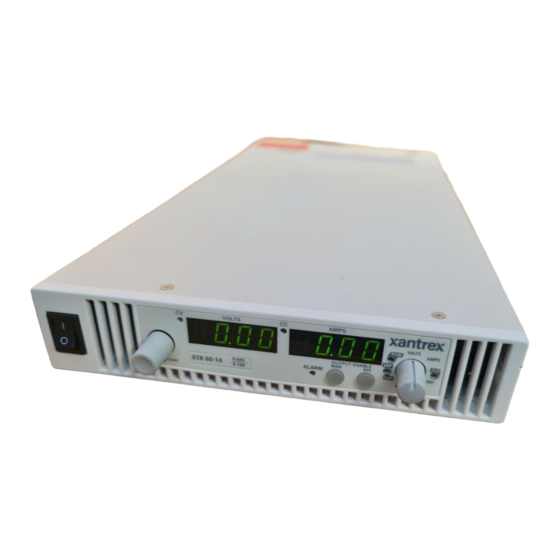
Introduction Front Panel Figure 1-1 XTR 850 Watt Front Panel Item Description Front panel power switch Front panel display. See Figure 1-2 for details. Air Intake Vents M370046-01... -
Page 27: Front Panel Display And Controls
Front Panel Front Panel Display and Controls Figure 1-2 Front Panel Display and Controls Item Description Rotary knob/Enter button Constant Voltage (CV) Mode LED (green) Output Voltage Display Constant Current (CC) Mode LED (green) Output Current Display Alarm Indicator LED (red) OUTPUT ON/OFF button Auxiliary Output ON/OFF (AUX ON/OFF) button 9-Position Mode Control Knob. -
Page 28: Rear Panel Connectors
Introduction Rear Panel Connectors 100 - 240 Vac 47-63 Hz, 11.5 –6A MADE IN CANADA Figure 1-3 Rear Panel: 6 V to 40 V Models 100 - 240 Vac 47-63 Hz, 11.5 –6A MADE IN CANADA Figure 1-4 Rear Panel: 60 V to 150 V Models 100 - 240 Vac 47-63 Hz, 11.5 –6A MADE IN CANADA... - Page 29 Rear Panel Connectors Item Description 6 V– 40 V Models: DC Output Terminal Positive 60 V–150 V Models: DC Output Connectors Positive (6.5 mm hole diameter) 300 V–600 V Models: DC Output Connectors Positive 6 V– 40 V Models: DC Output Terminal Negative 60 V–150 V Models: DC Output Connectors Negative (6.5 mm hole diameter) 300 V–600 V Models: DC Output Connectors Negative 3 (J2)
-
Page 31: Installation
Installation Chapter 2, Installation, provides information and procedures for inspecting, installing, and testing the power supply. -
Page 32: Basic Setup Procedure
Installation Basic Setup Procedure Table 2-1 provides a summary of the basic setup procedure with references to the relevant sections in this chapter. Refer to this table if you are unfamiliar with the installation requirements for the power supply. Complete each step in the sequence given. Table 2-1 Basic Setup Procedure Step Description... -
Page 33: Step 1: Inspecting And Cleaning
2. Ensure that the packing box contains the 7.5 foot (2.5 m) power cord. 3. If you see external damage or suspect internal damage, contact Xantrex Customer Service (see Contact Information on page iii) for an assessment. If the unit is damaged, save all packing materials and notify Xantrex Customer Service immediately. -
Page 34: Step 2: Location And Mounting
For a list of the part numbers, see “Part Numbers for Rack Mount Kits” on page iii. Installation information for the different rack mount options are provided with the rack mount kits. For XTR product support, visit www.xantrex.com and navigate to the XTR home page. Ventilation Whether operating the power supply in a rack or on a bench, allow air to reach the ventilation inlets on the front and rear of the unit for cooling. -
Page 35: Step 3: Connecting Ac Input Power
Step 3: Connecting AC Input Power Step 3: Connecting AC Input Power WARNING: Shock hazard Disconnect AC power from the unit before removing the cover. Even with the front panel power switch in the Off position, live line voltages are exposed when the cover is removed. -
Page 36: Step 4: Selecting Load Wires
Installation Step 4: Selecting Load Wires This section provides recommendations for selecting minimum load wire sizes. Load Wiring To select the wiring for connecting the load to the power supply, consider the following factors: • Insulation rating of the wire. •... -
Page 37: Figure 2-1 Maximum Load Wire Length For 1 V Line Drop
Step 4: Selecting Load Wires Maximum Load Wiring Length For Operation With Sense Lines Figure 2-1 Maximum Load Wire Length for 1 V Line Drop Noise and Impedance Effects To minimize noise pickup or radiation, use shielded twisted pair wiring of the shortest possible length for load sense wires. -
Page 38: Step 5: Performing Functional Tests
Installation Step 5: Performing Functional Tests The functional test procedures include: • Power-on and front panel functional checks • Voltage mode operation and current mode operation checks. For information on local operation, see “Local Operation” on page 3–1 for adjusting front panel controls and settings. Powering the Power Supply On/Off To power on the power supply: 1. -
Page 39: Voltage And Current Mode Operation Checks
Step 5: Performing Functional Tests Voltage and Current Mode Operation Checks To perform the voltage and current mode operation checks: 1. Ensure that the front panel power switch is in the On position and the output is disconnected. 2. If the OUTPUT ON/OFF button is illuminated, press the button to turn off the output. -
Page 40: Step 6: Connecting Loads
Installation Step 6: Connecting Loads This section describes how to connect loads to the power supply for both single and multiple loads. WARNING: Shock hazard There is a shock hazard at the power supply output when operating at an output greater than 40 V. -
Page 41: Inductive Loads
Step 6: Connecting Loads Inductive Loads To prevent damage to the power supply from inductive kickback, connect a diode across the output. The diode must have a voltage rating at least 20% greater than the power supply's output voltage and have a current rating greater than or equal to the power supply's output rating. -
Page 42: Connecting Multiple Loads
Installation Connecting Multiple Loads The proper connection of distributed loads is an important aspect of power supply use. The common method of connection is a radial load connection. Power is connected to each load individually from a single pair of terminals designated as the positive and negative distribution terminals. -
Page 43: Step 7: Connecting Remote Sensing
Step 7: Connecting Remote Sensing Step 7: Connecting Remote Sensing WARNING: Shock hazard There is a potential shock hazard at the sense connectors when using a power supply at an output greater than 40 V. Select wiring with a minimum insulation rating equivalent to the maximum output voltage of the power supply for use as local sense jumpers or for remote sense wires. - Page 44 Installation 3. Connect one end of the shielded twisted pair wire to the chassis ground point on the power supply. 4. Connect the positive sense line (+SNS) from the positive regulation point as close as possible to the load terminals to pin J1.1. 5.
-
Page 45: Local Operation
Local Operation Chapter 3, Local Operation, provides the procedures for local (front panel) operation such as: • Configuring settings. • Operating in constant voltage mode and constant current mode. • Using the protection features. • Using multiple power supplies. -
Page 46: Introduction
Local Operation Introduction Once you have installed the power supply and connected both the AC input power and the load (covered in “Installation” on page 2–1), the power supply is ready for local operation. To turn the power supply on, see “Powering the Power Supply On/Off”... -
Page 47: Coarse And Fine Adjustment Modes
Configuring Settings from the Front Panel Coarse and Fine Adjustment Modes Coarse When using local operation to set the current and voltage set points, enter adjustment the coarse adjustment mode followed by the fine adjustment mode. The mode coarse adjustment mode quickly adjusts the settings in large increments to reach the desired value. - Page 48 Local Operation Table 3-1 Select and Set from the Front Panel 9 Positions on the Mode Pressing the Enter Button lets Control Knob Turning the Rotary Knob lets you… you… CAP (Current Analog Select the programming source and Set the value selected and Programming) select the range.
-
Page 49: Navigating The Menu System
Navigating the Menu System Navigating the Menu System The menu system of the XTR follows a select and set model with the exception of the VOL and CUR modes. See “Setting VOL and CUR Modes”. The general procedure for setting up the features in the select and set model is: 1. - Page 50 Local Operation To access the tracking mode for entering voltage and current: 1. Select the VOL or CUR position on the mode control knob. If the set point is blinking, the unit is in coarse tracking mode. • When the VOL mode is selected, the voltage set point will blink in the output voltage display.
-
Page 51: Normal Display Mode And Inactivity Timeout
Navigating the Menu System Normal Display Mode and Inactivity Timeout Normal display mode appears on the output voltage and current displays when the configuration changes from the front panel have been completed or when the inactivity timeout occurs (default is 3 seconds). Normal display mode shows the output voltage and current values. -
Page 52: Figure 3-3 Front Panel Menu System
Local Operation Coarse Volt Tracking Fine Volt Tracking Coarse Volt Pre-Set Fine Volt Pre-Set Coarse Current Tracking Fine Current Tracking Coarse Current Pre-Set Fine Current Pre -Set Fold Delay Fold Delay None OVP Coarse Adjust OVP Fine Adjust UVP Coarse Adjust UVP Fine Adjust Overheat Protection On/Off... -
Page 53: Display Messages On The Front Panel
Display Messages on the Front Panel Display Messages on the Front Panel The front panel displays on the power supply will use text as shown in Table 3-2 to indicate the status or mode. Table 3-2 Front Panel Display Text Display Text Text Description Negative Polarity... - Page 54 Local Operation Table 3-2 Front Panel Display Text Display Text Text Description LE U Voltage APG Level Lock LOCL Local Over Current Protection Over Temperature Protection Over Voltage Protection OvPF Over Voltage Protection fine adjustment OUPC OVP Calibration Polarity Protection mode Power Supply Unit R IS Isolated Resistive Analog Programming...
-
Page 55: Standard Operation
Standard Operation Standard Operation The power supply can be controlled by two methods, either from the front panel or from any of the remote interfaces. Front panel control is referred to as local operation (default setting) while control via any of the remote interfaces is called remote operation. - Page 56 Local Operation Constant Voltage Mode Operation If the output is enabled and the configured current set point is much higher than the requirements for the attached load, then the voltage will rise until it reaches the voltage set point. When the output voltage reaches the voltage set point, it stops rising.
-
Page 57: Figure 3-4 Operating Modes
Standard Operation Figure 3-4 Operating Modes To set voltage set point SET): 1. Turn the mode control knob to the VOL position or press the Rotary knob/Enter button if the mode control knob is already at the VOL position. The voltage set point is blinking in the output voltage display. The output current will be displayed in the output current display. - Page 58 Local Operation Important: The control circuits have been designed to allow you to set the output voltage up to 105% over the model-rated maximum value. The power supply will operate within these extended ranges, but full performance to specification is not guaranteed. The SCPI command (s) for these instructions are: Quick Tip Remote operation...
-
Page 59: Shipped Configuration (Local Operation)
Turning the Output On/Off Shipped Configuration (Local Operation) The power supply is configured for local operation at the factory. See Table 3-3 for a summary of this configuration. For more information on default settings, see Table 3-9 on page 3–38. Table 3-3 Shipped Configuration Local Control Configuration Additional References... -
Page 60: Turning The Auxiliary Output On/Off
Local Operation Turning the Auxiliary Output On/Off To turn on the auxiliary output: ◆ Press the AUX ON/OFF button on the front panel. The AUX ON/OFF button will illuminate. The auxiliary output will not turn on if the external Important: AUX_ON_OFF signal line is being used to disable the auxiliary outputs. -
Page 61: Auxiliary Auto Start Mode
Auxiliary Auto Start Mode Auxiliary Auto Start Mode The Auxiliary Auto Start mode determines the state of the auxiliary output after a complete power cycle (all front panel LEDS are not illuminated). With Auxiliary Auto Start mode turned to On, the auxiliary output will be activated after the power supply is powered up again. -
Page 62: Alarms And Errors
Local Operation Alarms and Errors Several conditions can cause alarms in the XTR. Some conditions are: • From user configurable features. • Controlled in hardware and will trigger regardless of configuration. All alarms, with the exception of the Fan alarm, will result in the output of the power supply being disabled. -
Page 63: Clearing Alarms
Alarms and Errors Clearing Alarms Clearing Triggered and Manual Alarms To clear a triggered alarm, use one of the following methods: • Turn the power supply Off and then On. • Press and hold the Rotary knob/Enter button for 3 seconds. •... -
Page 64: Front Panel Alarm Led
Local Operation Clearing Automatic Alarms Some alarms will clear automatically when the condition that caused the alarm is no longer present. When an alarm automatically clears, the output voltage and current displays will return to normal, but the ALARM LED will remain illuminated to indicate that an alarm has occurred. If an automatic alarm is triggered, the normal alarm clearing procedure still applies. -
Page 65: Alarm Masking
Alarms and Errors Alarm Masking It is possible to completely disable some alarms through the use of the alarm mask. If an alarm is masked then this masking will prevent it from registering in the SCPI conditions registers as well as not triggering the alarm. -
Page 66: Alarm Output Latching
Local Operation Alarm Output Latching When an alarm is triggered, the output will be disabled with the exception of the Fan alarm. When an alarm is cleared, the alarm output latch determines if the output should be re-enabled to the state before the alarm occurred or if the output should remain in the off state. -
Page 67: Setting Foldback Mode
Setting Foldback Mode Setting Foldback Mode Foldback mode is used to disable the output when a transition is made between the operating modes. The power supply will turn off/disable the output and lock in foldback mode after a specified delay if the power supply transitions into CV mode or into CC mode, depending on the foldback mode settings. -
Page 68: Resetting Activated Foldback Protection
Local Operation 4. Press the Rotary knob/Enter button to commit the setting once the desired value has been set. 5. The green FLD LED will turn off and the display will return to the normal display mode. The SCPI command (s) for these instructions are: [:]OUTPut[<channel>]:PROTection:FOLDback[:MODE] [:]OUTPut[<channel>]:PROTection:FOLDback:LATCh Important:... -
Page 69: Using Over Voltage Protection (Ovp)
Using Over Voltage Protection (OVP) Using Over Voltage Protection (OVP) The OVP circuit protects the load in the event of an analog programming error, an incorrect voltage control adjustment, or a power supply failure. The OVP circuit monitors the output voltage at the output of the power supply and will disable the output whenever a preset voltage set point is exceeded. -
Page 70: Defining The Ovp Set Point
Local Operation Defining the OVP Set Point To define the OVP set point: 1. Turn the power supply On. Ensure the voltage is lower than the desired set point. 2. Set the output to the desired voltage. OVP can be set without setting desired output voltage first. 3. -
Page 71: Using Under Voltage Protection (Uvp)
Using Under Voltage Protection (UVP) Using Under Voltage Protection (UVP) UVP will not be active for voltage set points that are less than 1% Important: of model voltage. The UVP prevents voltage settings below a set value. The UVP lets you create a voltage window of operation when used in conjunction with the OVP setting. -
Page 72: Defining The Uvp Set Point
Local Operation Defining the UVP Set Point To define the UVP set point: 1. Turn the power supply On. 2. Set the output to the desired voltage. 3. Turn the mode control knob to the PRT position. PRo OUP is displayed. 4. -
Page 73: Using Over Temperature Protection Lock (Otp)
Using Over Temperature Protection Lock (OTP) Using Over Temperature Protection Lock (OTP) The OTP lock protects the power supply in the event of an over temperature alarm. This alarm could be caused by ventilation restriction or overheating due to fan failure. Two modes are available: •... -
Page 74: Using The External Shutdown Function
Local Operation Using the External Shutdown Function Use the external shutdown function to enable or disable the output of the power supply via a logic level signal. When the external shutdown is triggered, the power supply will display SD POL on the output voltage and current displays and the ALARM LED will illuminate. -
Page 75: Defining The Polarity Of The External Shutdown Signal
Using the External Shutdown Function Defining the Polarity of the External Shutdown Signal 1. Turn the mode control knob to the PRT position or press the Rotary knob/Enter button if the control knob is already at the PRT position. PrO OUP is displayed on the output voltage display. 2. -
Page 76: Interlock Function
Local Operation Interlock Function The Interlock function can be used to wire an external shutoff switch that can be used to enable or disable the power supply output. When the switch is closed the power supply will operate normally. If the switch is opened, the power supply will trigger the interlock alarm. -
Page 77: Power On Status Signal
Hardware Malfunction Alarms Power On Status Signal Power On Status signal indicates a fault condition in the power supply. Power On Status signal is a TTL output signal at Pin J2.13 with reference to COM_ISOLATED (Pin J2.2 or Pin J2.6). During normal operation, the Power On Status signal will be high. -
Page 78: Current Configuration Memory Settings
Local Operation Current Configuration Memory Settings The power supply will save the unit settings at the time of power down. These settings will be loaded when the power is restored to the unit or the power supply is powered up again. Table 3-7 lists the settings that are saved and recalled on a power cycle event. -
Page 79: User Setting Memory Locations
User Setting Memory Locations User Setting Memory Locations There are three user setting memory locations available for storing frequently used configurations. These user setting memory locations help to facilitate multiple users of an XTR power supply who have different setups or when multiple loads are used that have different requirements. Table 3-8 lists the values that are stored in each user setting memory location. -
Page 80: Recalling User Setting Memory Locations
Local Operation 4. The setting has now been saved to the selected user setting memory location. The SCPI command (s) for these instructions are: *SAV [:]SYSTem[<channel>]:SAVE Recalling User Setting Memory Locations This feature recalls settings that were previously saved. To load user setting memory locations: 1. -
Page 81: Local Lockout
Local Lockout Local Lockout Local lockout is a feature that allows the front panel to be locked so that accidental button presses are ignored. This feature is often used to lockout the front panel when you are controlling the power supply from a remote location. -
Page 82: Resetting The Power Supply
Local Operation Resetting the Power Supply The reset is used to clear the parameters to the factory default values. To perform a reset: 1. Turn the power supply to Off then On. When the unit is powering on, 8888 8888 is displayed on the output voltage and current displays. - Page 83 Resetting the Power Supply Table 3-9 Power Supply Default Settings Parameter Setting Foldback trigger None Foldback delay 0.5 s Current Share Mode MASTer Alarm Output Latches 263 (0 × 107, all latches enabled) Alarms Mask 2047 (0 × 7FF, all enabled) Interlock Disabled Voltage Analog Programming...
-
Page 84: Using Multiple Power Supplies
Local Operation Using Multiple Power Supplies WARNING: Shock hazard There is a shock hazard at the load when using a power supply at an output of greater than 40V or a combined output of greater than 40V. To protect personnel against accidental contact with hazardous voltages created by a series connection, ensure that the load, including connections, has no live parts which are accessible. -
Page 85: Figure 3-5 Split Supply Operation
Using Multiple Power Supplies Power Supply Common Load Power Supply Figure 3-5 Split Supply Operation M370046-01 3-41... -
Page 86: Configuring Multiple Supplies For Series Operation
Local Operation Configuring Multiple Supplies for Series Operation A maximum of two power supplies of the same rating can be connected in series to increase the output voltage. CAUTION: Equipment damage When two power supplies are connected in series, they should be programmed to the same output voltage to prevent damage to the lower voltage supply at short circuit condition. -
Page 87: Figure 3-7 Load Connections In Remote Sensing Mode
Using Multiple Power Supplies Connecting to the Load in Remote Sensing Mode Connect the negative (–) output terminal of one power supply to the positive (+) output terminal of the next power supply. The more positive supply’s positive sense line should connect to the positive terminal of the load (or distribution point). -
Page 88: Configuring Multiple Supplies For Current Sharing Operation (Apg Method)
Local Operation Configuring Multiple Supplies for Current Sharing Operation (APG Method) Up to four power supplies can be connected in parallel to increase the output current. One of the units will operate as the master unit and the remaining units will operate as slave units controlled by the master unit. The master unit uses the analog programming lines to set the output voltages and currents of the slave units to match its output. - Page 89 Using Multiple Power Supplies Setting Over Voltage Protection (OVP) The master unit’s OVP should be programmed to the desired OVP level. The OVP of the slave units should be programmed to a higher value than the master OVP. When the master unit shuts down, it will program the outputs of the slave units to zero volts.
-
Page 90: Connecting To The Load In Local Sensing Mode (Parallel Control Method)
Local Operation Connecting to the Load in Local Sensing Mode (Parallel Control Method) Connect the power supplies in parallel to obtain a single output supply with a higher output current set point. Set all of the outputs to the same voltage before connecting the positive (+) and negative (–) terminals in parallel. -
Page 91: Connecting To The Load In Remote Sensing Mode (Parallel Control Method)
Using Multiple Power Supplies Connecting to the Load in Remote Sensing Mode (Parallel Control Method) Figure 3-9 Load Connections in Remote Sensing Mode (Parallel Control Method) M370046-01 3-47... - Page 92 3-48...
-
Page 93: Analog Programming (Apg) And Isolated Analog Programming (Isol)
Analog Programming (APG) and Isolated Analog Programming (ISOL) Chapter 4, Analog Programming (APG) and Isolated Analog Programming (ISOL), provides information and procedures for analog and isolated analog programming of the power supply. -
Page 94: Introduction
Analog Programming (APG) and Isolated Analog Programming (ISOL) Introduction The rear panel connectors J1 and J3 provide an option to control and monitor the output of the power supply with analog signals. Connector J1 provides a non-isolated analog interface where all signals are referenced to the negative output terminal of the power supply. -
Page 95: Remote Programming Options
Introduction Remote Programming Options Analog Monitor Signals There are four monitor lines for analog programming the pin name and the related APG mode, which are listed in Table 4-1. All of these lines are provided to give analog feedback. The output from these monitor lines is a value scaled to the Analog Programming level set for the corresponding analog programming type. -
Page 96: Table 4-2 Remote Programming Options
Analog Programming (APG) and Isolated Analog Programming (ISOL) Auxiliary Outputs The auxiliary outputs are an additional isolated source. The auxiliary output has two outputs: +5 V output on J3.9 and a +15 V output on J3.11. The auxiliary output operates independently of the main output. It is enabled or disabled from the front panel by pressing the AUX ON/OFF button. -
Page 97: Analog Programming (Apg) Connector J1
Introduction Analog Programming (APG) Connector J1 The APG connector is an 18-pin connector. See Figure 4-1. The APG connector provides access to the following functions: • Sense control • Analog programming and monitoring. Jumper Jumper +SNS REF_I -SNS EXT_CC_CV CUR_MON VOL_MON VOL_PR CUR_PR... - Page 98 Analog Programming (APG) and Isolated Analog Programming (ISOL) Table 4-3 APG Pins and Functions J1 Reference Function J1.9 VOL_PR Analog Voltage Programming Input J1.10 CUR_PR Analog Current Programming Input J1.11 VOL_RES_PR Voltage Resistive Programming Input J1.12 CUR_RES_PR Current Resistive Programming Input J1.13 Voltage Monitor.
-
Page 99: Figure 4-2 Inserting Screwdriver Into Spring Terminal Block
Introduction Making Control Connections CAUTION: Equipment damage Before making connections from external circuits to the Analog Programming Connector, turn the front panel power switch to Off and wait until the front panel displays are not illuminated. CAUTION: Equipment damage Program/monitor signal and return are internally connected to the power supply negative output (-S). - Page 100 Analog Programming (APG) and Isolated Analog Programming (ISOL) Wiring WARNING: Shock hazard There is a potential shock hazard at the output when using a power supply with a rated output greater than 60 V. Use load wiring with a minimum insulation rating equivalent to the maximum output voltage of the power supply.
-
Page 101: Analog Programming Mode
Analog Programming Mode Analog Programming Mode For more details about connections for your particular model, see “Rear Panel Connectors” on page 1–6 or “” on page 1–7. CAUTION: Equipment damage The program/monitor signal and return are internally connected to the power supply’s negative output. -
Page 102: Voltage-Controlled Voltage Apg Setup
Analog Programming (APG) and Isolated Analog Programming (ISOL) Voltage-Controlled Voltage APG Setup Activating APG Voltage Mode To activate APG voltage mode using an external voltage source: 1. Turn the mode control knob to the VAP position or press the Rotary knob/Enter button if the control knob is already at the VAP position. - Page 103 Analog Programming Mode Query for Analog Voltage Input Level To query for analog voltage input level from non-isolated input: 1. Turn the mode control knob to the VAP position or press the Rotary knob/Enter button if the control knob is already at the VAP position. UAPr is displayed on the output voltage display.
-
Page 104: Voltage-Controlled Current Apg Setup
Analog Programming (APG) and Isolated Analog Programming (ISOL) Voltage-Controlled Current APG Setup Activating APG Current Mode To activate APG current mode using an external voltage source: 1. Turn the mode control knob to the CAP position or press the rotary knob/Enter button if the control knob is already at the CAP position. - Page 105 Analog Programming Mode Query for Analog Current Input Level To query for analog current input level from non-isolated input: 1. Turn the mode control knob to the CAP position or press the Rotary knob/Enter button if the control knob is already at the CAP position. CAPr is displayed on the output voltage display.
-
Page 106: Figure 4-6 Programming Output Voltage Using An External Resistor
Analog Programming (APG) and Isolated Analog Programming (ISOL) Analog Programming With External Resistor The pin numbers are described in Table 4-3 on page 4–5. J1.9 J1.11 J1.7 Figure 4-6 Programming Output Voltage using an External Resistor Figure 4-7 Programming Output Current using an External Resistor 4-14 M370046-01... -
Page 107: Resistive-Controlled Voltage Apg Setup
Analog Programming Mode Resistive-Controlled Voltage APG Setup To activate APG voltage mode using an external resistor: 1. Turn the mode control knob to the VAP position or press the rotary knob/Enter button if the control knob is already at the VAP position. UAPr is displayed on the output voltage display. - Page 108 Analog Programming (APG) and Isolated Analog Programming (ISOL) Query for Analog Voltage Input Level To query for analog voltage input level from non-isolated input: 1. Turn the mode control knob to the VAP position or press the Rotary knob/Enter button if the control knob is already at the VAP position. UAPr is displayed on the output voltage display.
-
Page 109: Resistive-Controlled Current Apg Setup
Analog Programming Mode Resistive-Controlled Current APG Setup To activate APG current mode using an external resistor source: 1. Turn the mode control knob to the CAP position to press the Rotary knob/Enter button if the control knob is already at CAP position. CAPr is displayed on the output voltage display. - Page 110 Analog Programming (APG) and Isolated Analog Programming (ISOL) Query for Analog Current Input Level To query for analog current input level from non-isolated input: 1. Turn the mode control knob to the CAP position or press the Rotary knob/Enter button if the control knob is already at the CAP position. CAPr is displayed on the output voltage display.
-
Page 111: Voltage And Current Readback
Analog Programming Mode Voltage and Current Readback The pin numbers are described in Table 4-3 on page 4–5. Figure 4-8 Voltage Readback Using APG Connector J1 Figure 4-9 Current Readback Using APG Connector J1 M370046-01 4-19... -
Page 112: Isolated Analog Programming Mode (Isol)
Analog Programming (APG) and Isolated Analog Programming (ISOL) Isolated Analog Programming Mode (ISOL) See “Rear Panel Connectors” on page 1–6 or “” on page 1–7 for more details about connections. AUX Output and Isolated Analog Programming (ISOL) Connector The AUX Output and Isolated Analog Programming (ISOL) Connector is a 15-pin female DSUB connector. -
Page 113: Table 4-4 Aux Output And Isol Connector Pins And Functions J3
Isolated Analog Programming Mode (ISOL) Table 4-4 AUX Output and ISOL Connector Pins and Functions J3 Reference Function J3.1 AUX_ON_OFF Auxiliary On/Off J3.2 COM_ISOLATED Isolated Common (Isolated from Main Output and Communication. Return wire for +5 V, +15 V Auxiliary Voltage. J3.3 IS_VOL_PR_VOL Isolated Analog Voltage Programming Input... - Page 114 Analog Programming (APG) and Isolated Analog Programming (ISOL) CAUTION: Equipment damage Do not drive or apply a voltage to pins J3.14 (Inter_Lock 1) or to pins J3.15 (Inter_Lock 2). 4-22 M370046-01...
-
Page 115: Figure 4-11 Programming Output Voltage Using An Isolated External Voltage Source
Isolated Analog Programming Mode (ISOL) Making ISOL Control Connections CAUTION: Equipment damage Before making connections from external circuits to the Isolated Analog Programming Connector, turn the front panel power switch to off and wait until the front panel displays have gone out. For most connectors and jumpers, use any suitable wire such as 22 AWG stranded wire. -
Page 116: Voltage-Controlled Voltage Isol Setup
Analog Programming (APG) and Isolated Analog Programming (ISOL) Voltage-Controlled Voltage ISOL Setup Activating ISOL Programming Voltage Mode To activate ISOL programming voltage mode with an external voltage source: 1. Turn the mode control knob to the VAP position or press the rotary knob/Enter button if the control knob is already at the VAP position. - Page 117 Isolated Analog Programming Mode (ISOL) Query for ISOL Voltage Input Level To query for ISOL voltage input level from non-isolated input: 1. Turn the mode control knob to the VAP position or press the Rotary knob/Enter button if the control knob is already at the VAP position. UAPr is displayed on the output voltage display.
-
Page 118: Voltage-Controlled Current Isol Setup
Analog Programming (APG) and Isolated Analog Programming (ISOL) Voltage-Controlled Current ISOL Setup Activating ISOL Programming Current Mode 1. Turn the mode control knob to the CAP position or press the rotary knob/Enter button if the control knob is already at the CAP position. CAPr is displayed on the output voltage display. - Page 119 Isolated Analog Programming Mode (ISOL) Query for ISOL Current Input Level To query for ISOL current input level from non-isolated input: 1. Turn the mode control knob to the CAP position or press the Rotary knob/Enter button if the control knob is already at the CAP position. CAPr is displayed on the output voltage display.
-
Page 120: Figure 4-13 Programming Output Voltage Using An Isolated External Resistor
Analog Programming (APG) and Isolated Analog Programming (ISOL) Analog Programming With External Resistor The pin numbers are described in Table 4-4 on page 4–21. Figure 4-13 Programming Output Voltage using an Isolated External Resistor Figure 4-14 Programming Output Current using an Isolated External Resistor 4-28 M370046-01... -
Page 121: Resistive-Controlled Voltage Isol Setup
Isolated Analog Programming Mode (ISOL) Resistive-Controlled Voltage ISOL Setup Activating ISOL Programming Voltage Mode To activate ISOL programming voltage mode using an external resistor: 1. Turn the mode control knob to the VAP position or press the rotary knob/Enter button if the control knob is already at the VAP position. UAPr is displayed on the output voltage display. - Page 122 Query for ISOL Voltage Input Level To query for ISOL voltage input level from non-isolated input: 1. Turn the mode control knob to the VAP position or press the Rotary knob/Enter button if the control knob is already at the VAP position. UAPr is displayed on the output voltage display.
-
Page 123: Resistive-Controlled Current Isol Setup
Isolated Analog Programming Mode (ISOL) Resistive-Controlled Current ISOL Setup Activating ISOL Resistive-Controlled Current Setup 1. Turn the mode control knob to the CAP position or press the rotary knob/Enter button if the control knob is already at the CAP position. CAPr is displayed on the output voltage display. - Page 124 Analog Programming (APG) and Isolated Analog Programming (ISOL) Query for ISOL Current Input Level To query for ISOL current input level from non-isolated input: 1. Turn the mode control knob to the CAP position or press the Rotary knob/Enter button if the control knob is already at the CAP position. CAPr is displayed on the output voltage display.
-
Page 125: Voltage And Current Readback (Isolated)
Voltage and Current Readback (Isolated) Voltage and Current Readback (Isolated) The pin numbers are described in Table 4-4 on page 4–21. Figure 4-15 Isolated Voltage Monitoring Figure 4-16 Isolated Current Monitoring Query Remote Control Source State The SCPI command for these instructions are: Quick Tip Remote operation [:]SYSTem[<channel>]:REMote:SOURce[:VOLTage]? - Page 126 Analog Programming (APG) and Isolated Analog Programming (ISOL) 4-34 M370046-01...
-
Page 127: Remote Operation
Remote Operation Chapter 5, Remote Operation, describes the remote operation of the XTR power supply via the communication ports. -
Page 128: Introduction
The XTR implements the SCPI standard as its command line interface for remotely controlling the power supply. Additionally, a small subset of legacy Xantrex commands has been provided for ease of use and backwards compatibility. -
Page 129: Hardware And Connection Setup
Hardware and Connection Setup Hardware and Connection Setup This section provides information on setting up the hardware and is organized into setup for each hardware type. Once the setup has been successfully completed, data can be sent to and responses received from the power supply. -
Page 130: Table 5-2 Db-9 Pinouts
Remote Operation Table 5-1 Remote Control Connector Pins and Functions J4 and J6 Reference Direction Function J6.10 – – J6.11 RXD+ Input RS-485 receiving J6.12 RXD– Input RS-485 receiving J6.13 TXD+ Output RS-485 transmitting J6.14 TXD– Output RS-485 transmitting J6.15 –... -
Page 131: Figure 5-2 Rs-232 Communication Cable With Db-9 Pinout
Hardware and Connection Setup DB-9 Pinout DB-9 connector on PC RJ-45 plug Figure 5-2 RS-232 Communication Cable with DB-9 Pinout RS-232 Communication Cable with RJ-45 to DB-25 Communication control cable with DB-25 pinout (male) on the PC side and RJ-45 shielded connector on the power supply. The cable length should be 9.84 feet (3 m) or longer. -
Page 132: Figure 5-4 Rs-232 Communication Cable With Db-25 Pinout
Remote Operation DB-25 connector on PC RJ-45 plug Figure 5-4 RS-232 Communication Cable with DB-25 Pinout Completing the Setup To complete the setup: ◆ Configure the XTR to use the 232 remote interface and set up the terminal that will be used on the connected PC. See the sections entitled“Selecting the Appropriate Communication Port”... -
Page 133: Configuring Remote Control Using
Hardware and Connection Setup Configuring Remote Control Using RS-485 RS-485 Communication Cable with RJ-45 to DB-9 Communication control cable with DB-9 pinout (female) on the PC side (see Figure 5-2) and RJ-45 shielded connector on the power supply. The cable length should be 9.84 feet (3 m) or longer. Table 5-5 DB-9 Pinouts Name Description... -
Page 134: Figure 5-6 Rs-485 Communication Cable From Master To Slave Unit
Remote Operation RS-485 Communication Cable with Two RJ-45s Use the top connector of the two 8-pin RJ-45 jacks, as shown in Figure 5-1, to connect to the RS-485 remote interface. Communication cable with two RJ-45 shielded connectors (see Figure 5-3) connecting the master unit to the slave unit. -
Page 135: Configuring Remote Control Using The Usb Connector
To download and install a virtual COM port (VCP) driver: 1. Go to www.xantrex.com and navigate to the XTR product web page. 2. Click the download link to download the driver. 3. Download the appropriate virtual COM port (VCP) drivers for your operating system (with enhanced BM series support). -
Page 136: Figure 5-7 Found New Hardware Wizard
Remote Operation Figure 5-7 Found New Hardware Wizard 7. Click Next. 8. On the Install Hardware Device Driver screen, select “Search for a suitable driver for my device (recommended)” and click Next. See Figure 5-8. Figure 5-8 Install Hardware Device Drivers 5-10 M370046-01... -
Page 137: Figure 5-9 Completing The New Hardware Wizard
Hardware and Connection Setup 9. In the Locate Driver Files dialog box, in the field Optional Search Locations, select Specify A Location and click Next. 10. On the next screen, enter the file path “C:\FTDI” and click OK. 11. On the next screen, select “Driver Files Search Results” and click Next. -
Page 138: Figure 5-10 Device Manager
Remote Operation To verify that the device has been installed: 1. In Control Panel, go to System, click the Hardware tab and click on Device Manager. 2. On the View menu, select Devices by Type. 3. To change the virtual COM port properties, select the USB Serial Port and then Click Properties. -
Page 139: Figure 5-11 Communications Port (Com1) Properties
Hardware and Connection Setup Figure 5-11 Communications Port (COM1) Properties 5. In the COM port list, scroll to the required COM port. Figure 5-12 Completing the new hardware wizard 6. Click OK. Ensure that you do not select a COM port which is already in use. This selection is particularly useful for programs, such as HyperTerminal, which only work with COM1 through to COM4. - Page 140 Remote Operation Complete the Setup To complete the setup: ◆ Configure the XTR to use the USB remote interface and set up the terminal that will be used on the connected PC. See “Selecting the Appropriate Communication Port” on page 5–20 and “Terminal Configuration”...
-
Page 141: Ethernet (Enet) Or Gpib Connector (Optional)
Hardware and Connection Setup Ethernet (ENET) or GPIB Connector (Optional) The power supply can be programmed from a remote terminal using a General Purpose Interface Bus (GPIB interface) or Ethernet (ENET). If you have a GPIB or ENET card, see the XTR 850 Watt GPIB and Ethernet Interface Option Operating Manual (Part number M370046-06). - Page 142 Remote Operation Multiple Power Supply Setup Master Setup: ◆ Configure the master XTR by selecting the communication interface you wish to use to communication with the Master and follow the setup instruction in this chapter. Important: If either RS-232 or RS-485 are used for communication with the master, the data rate must be configured for 9600 bps to properly communicate with the slave units.
-
Page 143: Terminal Configuration
Terminal Configuration Terminal Configuration The terminal program allows serial communication with the power supply. To use a terminal program, set it up using the parameters from the following sections. If you wish to use HyperTerminal, see “HyperTerminal” on page 5–17 for instructions setting it up. Data Format Serial data format is 8 bit, one stop bit. -
Page 144: Figure 5-14 Usb Settings
Remote Operation This is the COM port that you have your serial cable hooked up to or in the case of USB the one that was configured to be used in the FDTI software. 5. Click OK when done. 6. Setup the data format to be used. See “Data Format” on page 5–17 for details. -
Page 145: Figure 5-15 Ascii Setup
Terminal Configuration Figure 5-15 ASCII Setup 11. Check the following boxes: • Send line ends with line feeds. • Echo typed characters locally. • Append line feeds to incoming line ends. • Wrap lines that exceed terminal width. 12. Click OK in the ASCII Setup window. 13. -
Page 146: Selecting The Appropriate Communication Port
Remote Operation Selecting the Appropriate Communication Port Five ports are available for remote digital programming and readback: • RS-232 • RS-485 • • GPIB (optional) • ENET (optional) To select a communication port: 1. Turn the mode control knob to PGM. rE is displayed in the output voltage display. -
Page 147: Multichannel Address Setting
Terminal Configuration Multichannel Address Setting The power supply multichannel address can be set to any address between 1 to 30. All units that are connected together via the RS-232 or RS-485 connector must have a unique multichannel address. To set the address: 1. -
Page 148: Remote Interface Addressing
Remote Operation Remote Interface Addressing All commands must be issued with a multichannel address or the device must be selected using the: *adr or :SYST[<channel>]:COMM[:MCH]:ADDR commands. Once a device is selected all commands sent without a multichannel address will be handled by the selected device. The use of multichannel addresses supersedes the selected device as the destination for a message. -
Page 149: Multichannel Commands Explained
Terminal Configuration Multichannel Commands Explained The use of multichannel addressing allows you to send messages to one device, more than one device or to all devices. Any of the remote interface types can be used to send a multichannel command through the device that is physically connected to the PC to all the devices, provided that all other devices are connected to via the RS-485 bus. - Page 150 Remote Operation Multichannel commands are particularly useful for configuring groups of devices that require identical configurations. The SCPI Commands for these instructions are: [:]<root command> <ALL|addr1>[,[ ]<addr2>][,[ ]<addr3>][,...]:<command> <parameter> For example: sour 1, 2, 3, 7:volt 4.5 syst4,5,6:oper:enab 255 syst ALL:clear output0:stat on 5-24 M370046-01...
-
Page 151: Status Reporting In Scpi
Terminal Configuration Status Reporting in SCPI The status reporting implemented in the XTR is primarily dictated by the SCPI standard. This section provides a high level review of the standard status reporting required by SCPI and then covers the XTR specific reporting that is implemented within the SCPI status reporting framework. -
Page 152: Figure 5-16 Scpi Status Reporting Model
Remote Operation QUEStionable Status VOLTage CURRent Error/Event Queue TIME POWer TEMPerature FREQuency PHASe MODulation CALIbration Available to designer Available to designer Available to designer Available to designer INSTrument Summary Command Warning Not Used* OPERation Status CALIbrating SETTing RANGing SWEeping MEASuring Waiting for TRIGger Summary Waiting for ARM Summary CORRecting... -
Page 153: Status Registers Model From Ieee 488.2
Status Registers Model from IEEE 488.2 Status Registers Model from IEEE 488.2 The IEEE 488.2 registers shown in the bottom rectangle of Figure 5-16 follow the IEEE 488.2 model for status registers. The IEEE 488.2 register only has enable registers for masking the summary bits. Figure 5-17 shows the details on the relationship between the mask/enable registers and the summary bits. -
Page 154: Status Byte
Remote Operation Status Byte The Status byte register contains the STB and RQS (MSS) messages as defined in 488.1. You can read the status byte register using a 488.1 serial poll or the 488.2 *STB? common command. The *STB? query causes the device to send the contents of the Status Byte Register and the Master Summary Status (MSS) summary message. -
Page 155: Message Available (Mav)
Status Byte Message Available (MAV) This bit is TRUE whenever the power supply is ready to accept a request by the Digital Programming Interface to output data bytes. This message is FALSE when the output queue is empty. Standard Event Status Summary (ESB) This bit is TRUE when a bit is set in the Standard Event Status Register. -
Page 156: Operation Status Register Summary (Osr)
Remote Operation Operation Status Register Summary (OSR) This bit is TRUE when a bit in the Operation Event Status Register is set and its corresponding bit in the Operation Status Enable Register is set. Service Request Enable Register The Service Request Enable Register allows you to select the reasons for the power supply to issue a service request. -
Page 157: Standard Event Status Register (Sesr)
Status Byte Standard Event Status Register (SESR) The standard event status register sets bits for specific events during power supply operation. All bits in the standard event status registers are set through the error event queue. The register is defined by IEEE 488.2 register and is controlled using 488.2 common commands: *ESE, *ESE?, and *ESR? as well as SCPI aliases for multichannel use. -
Page 158: Figure 5-18 Summary Of Standard Event Status Register
Remote Operation Figure 5-18 summarizes the Standard Event Status Register. Status Byte SESR Standard Event Register Summary Summary Status Register (SESR) Not Used Not Used Operation Complete Error/Event Queue Status Flag QUEStionable Status Summary Bit Not Used Not Used Query Error Device Dependent Error Execution Error OPERation Status Summary Bit... - Page 159 Status Byte Table 5-10 Standard Event Status Register Bit Weight Bit Name Description Command Error (CME) Set if an IEEE488.2 syntax error has been detected by the parser, an unrecognized header was received, or a group Execute Trigger was entered into the input buffer inside an IEEE 488.2 program message.
-
Page 160: Standard Scpi Register Structure
Remote Operation Standard SCPI Register Structure All registers except the SERS and Status registers will have the following structure which control how they report status information. In all subsequent figures that have SCPI registers, this structure will be condensed down into a single block to simplify the figures. The simplified block will show a 16-bit register and the summary bit. -
Page 161: Operation Status Register
OPERation Status Register OPERation Status Register The operation status register is a standard SCPI, 16-bit register which contains information about conditions which are part of the power supply's normal operation. The Operation Status data structure has the operation status register and two sub-registers to represent shutdown and protection shutdown. -
Page 162: Table 5-11 Operation Status Register
Remote Operation Table 5-11 OPERation Status Register Bit Weight Bit Name Description CALibrating Indicates that the supply is in CALibration Mode. SETTling Not implemented RANGing Not implemented SWEeping Not implemented MEASuring Not implemented Waiting for Arm Not implemented Waiting for Trigger Not implemented CORRecting Not implemented... -
Page 163: Table 5-12 Operation Shutdown Status Register
OPERation Status Register Table 5-12 OPERation SHUTdown Status Register Bit Weight Bit Name Description PROTection Reflects the summary of the PROTection sub- register. INTerlock The power supply is shut down by INTerlock signal. Not Used Not Used External Shutdown The power supply is shut down by External Shutdown signal. -
Page 164: Current Share Sub-Register
Remote Operation Current SHare Sub-Register This register shows the state of the current share configuration, which can either be set through the front panel Current Share Config menu, or through the SCPI command. The SCPI command (s) for these instructions are: [[:]SOURce]:COMBine:CSHare[:MODE] Table 5-14 OPERation CSHare Status Register Bit Weight Bit Name... -
Page 165: Operation Status Register Commands
OPERation Status Register Operation Status Register Commands The response format for all register queries will be in decimal notation. Query Operation Status Register Event SCPI command: [:]STATus[<channel>]:OPERation[:EVENt]? Query Operation Status Register Condition SCPI command: [:]STATus[<channel>]:OPERation:CONDition? Enable Operation Status Register SCPI command: [:]STATus[<channel>]:OPERation:ENABle <status-enable>... -
Page 166: Current Sharing Sub-Register Commands
Remote Operation Current Sharing Sub-Register Commands Query Current Share Event SCPI command: [:]STATus[<channel>]:OPERation:CSHare[:EVENt]? Query Current Share Condition SCPI command: [:]STATus[<channel>]:OPERation:CSHare:CONDition? Enable Current Share Sub-Register SCPI command: [:]STATus[<channel>]:OPERation: CSHare:ENABle <statusenable> Query format: [:]STATus[<channel>]:OPERation:CSHare:ENABle? Set Current Share Positive Transition Filter SCPI command: [:]STATus[<channel>]:OPERation:CSHare:PTRansition <status-enable>... -
Page 167: Shutdown Sub-Register Commands
OPERation Status Register Shutdown Sub-Register Commands Query Shutdown Event SCPI command: [:]STATus[<channel>]:OPERation:SHUTdown[:EVENt]? Query Shutdown Condition SCPI command: [:]STATus[<channel>]:OPERation:SHUTdown:CONDition? Enable Shutdown Sub-Register SCPI command: [:]STATus[<channel>]:OPERation: SHUTdown:ENABle <status- enable> Query format: [:]STATus[<channel>]:OPERation:SHUTdown:ENABle? Set Shutdown Positive Transition Filter SCPI command: [:]STATus[<channel>]:OPERation:SHUTdown:PTRansition <status-enable> Query format: [:]STATus[<channel>]:OPERation:SHUTdown:PTRansition? Set Shutdown Negative Transition Filter SCPI command:... -
Page 168: Protection Sub-Register Commands
Remote Operation Protection Sub-Register Commands Query Protection Event SCPI command: [:]STATus[<channel>]:OPERation:SHUTdown:PROTection[:EVENt]? Query Protection Condition SCPI command: [:]STATus[<channel>]:OPERation:SHUTdown:PROTection:CONDition? Enable Protection Sub-Register SCPI command: [:]STATus[<channel>]:OPERation: SHUTdown:PROTection:ENABle <status-enable> Query format: [:]STATus[<channel>]:OPERation:SHUTdown:PROTection:ENABle? Set Protection Positive Transition Filter SCPI command: [:]STATus[<channel>]:OPERation:SHUTdown:PROTection:PTRansition <stats-enable> Query format: [:]STATus[<channel>]:OPERation:SHUTdown:PROTection:PTRansition? Set Protection Negative Transition Filter SCPI command: [:]STATus[<channel>]:OPERation:SHUTdown:PROTection:NTRansition... -
Page 169: Questionable Status Register
QUEStionable Status Register QUEStionable Status Register The Questionable Status register is a standard SCPI, 16-bit register that stores information about questionable events or status during power supply operation. That is, bits in these registers may indicate that the output of the supply is of undesirable or questionable quality. The Questionable Status data structure consists of a questionable status register and two sub-registers representing the status of the voltage outputs and temperature. -
Page 170: Figure 5-21 Scpi Questionable Registers Fanout
Remote Operation S T A Tus:Q U E S tionable :V O LTage O ver V oltage P rotection (O V P ) U nder V oltage P rotection (U V P ) N ot U sed N ot U sed N ot U sed N ot U sed N ot U sed... - Page 171 QUEStionable Status Register Table 5-15 QUEStionable Status Register Bit Weight Bit Name Description VOLTage Summary of Voltage Register CURRent Not Implemented TIME Not Implemented POWer Not Implemented TEMPerature Summary of Temperature Register FREQuency Not Implemented PHASe Not Implemented MODulation Not Implemented CALibration Not Implemented Not Used...
-
Page 172: Voltage Sub-Register
Remote Operation VOLTage Sub-Register This shows whether the present voltage level is over or under the specified trip limit. Table 5-16 QUEStionable VOLTage Status Register Bit Weight Bit Name Description Over Voltage Protection Under Voltage Protection TEMPerature Sub-Register This shows whether the temperature of critical components is near or over the maximum operating temperature. -
Page 173: Questionable Status Register Commands
QUEStionable Status Register Questionable Status Register Commands Query Questionable Status Register Event SCPI command: [:]STATus[<channel>]:QUEStionable[:EVENt]? Query Questionable Status Register Condition SCPI command: [:]STATus[<channel>]:QUEStionable:CONDition? Enable Questionable Status Register SCPI command: [:]STATus[<channel>]:QUEStionable:ENABle <status-enable> Query Format: [:]STATus[<channel>]:QUEStionable:ENABle? Set Questionable Status Positive Transition Filter SCPI command: [:]STATus[<channel>]:QUEStionable:PTRansition <status- enable>... -
Page 174: Voltage Status Register Commands
Remote Operation Voltage Status Register Commands Query Voltage Status Register Event SCPI command: [:]STATus[<channel>]:QUEStionable:VOLTage[:EVENt]? Query Voltage Status Register Condition SCPI command: [:]STATus[<channel>]:QUEStionable:VOLTage:CONDition? Enable Voltage Status Register SCPI command: [:]STATus[<channel>]:QUEStionable:VOLTage:ENABle <status-enable> Query Format: [:]STATus[<channel>]:QUEStionable:VOLTage:ENABle? Set Voltage Status Positive Transition Filter SCPI command: [:]STATus[<channel>]:QUEStionable:VOLTage:PTRansition <status-enable>... -
Page 175: Temperature Status Register Commands
QUEStionable Status Register Temperature Status Register Commands Query Temperature Status Register Event SCPI command: [:]STATus[<channel>]:QUEStionable:VOLTage:TEMPerature [:EVENt]? Query Temperature Status Register Condition SCPI command: [:]STATus[<channel>]:QUEStionable:VOLTage:TEMPerature :CONDition? Enable Temperature Status Register SCPI command: [:]STATus[<channel>]:QUEStionable:VOLTage:TEMPerature :ENABle <status-enable> Query Format: [:]STATus[<channel>]:QUEStionable:VOLTage:TEMPerature :ENABle? Set Temperature Status Positive Transition Filter SCPI command: [:]STATus[<channel>]:QUEStionable:VOLTage:TEMPerature :PTRansition <status-enable>... -
Page 176: Scpi Error/Event Queue
Remote Operation SCPI Error/Event Queue The error/event queue contains items that include a numerical and textual description of the error or event. Querying for the full queue item (for example, with SYSTem:ERRor[:NEXT]?) will return a response with the following syntax: <Error/Event Number>, "<Error/Event Description>;<Optional Device Dependent Info>"... - Page 177 SCPI Error/Event Queue Examples: SYST:ERR? SYST:ERR:EVENT? Responses might be: -102, "syntax error;” 0, "No Error;" Querying For the Error Code Only It is possible to query for only the error code. When querying the error code only the response will be the numeric error code only, no additional description will be given.
-
Page 178: Reset Command
Remote Operation Reset Command The Reset command performs a device reset. The Reset command is the third level of reset in a three level reset strategy, set out in IEEE 488.2 (see IEEE 488.2 standard, section 17.1.2). The Reset command shall do the following: 1. -
Page 179: Clear All Status Registers
SCPI Error/Event Queue Clear All Status Registers Clear Status Command Clears all Event Registers, including the Status Byte, the Standard Event Status and the Error Queue. Command: *CLS [:]STATus[<channel>]:CLEar M370046-01 5-53... -
Page 180: Scpi Preset Status
Remote Operation SCPI Preset Status Configures the status data structures to ensure that certain events are reported at a higher level through the status-reporting mechanism. These events are summarized in the mandatory structures, the Operation Status Register and Questionable Status Register. The PRESet command affects only the enable registers and the transition filter registers of the status data structures. -
Page 181: Command Line Help System
SCPI Error/Event Queue Command Line Help System The Help system is made up of a series of commands that can be used to get help on all available commands and details on their syntax. The Help commands are: [:]SYSTem[<channel>]:HELP:HEADers? [:]SYSTem[<channel>]:HELP:SYNTax?'<command for which you want help>' [:]SYSTem[<channel>]:HELP:LEGacy? Querying Help for all Command Headers... - Page 182 Remote Operation *CLS/nquery/ *ESE *ESR?/qonly/ *SRE *SRE?/qonly/ *STB?/qonly/ *SAV *RCL *TRG/nquery/ *ADR *HELP?/qonly/ *ERR?/qonly/ [:]SYSTem:PROTection[:MASK] [:]SYSTem:ERRor[:NEXT]?/qonly/ [:]SYSTem:ERRor:CODE[:NEXT]?/qonly/ [:]SYSTem:ERRor:COUNt?/qonly/ Press any key to continue or ESC to quit... … [:]OUTPut:PROTection:FOLDback[:MODE] [:]OUTPut:PROTection:FOLDback:DELay [:]OUTPut:POLarity [:]OUTPut[:POWer][:STATe] [:]OUTPut[:POWer]:PON[:STATe] [:]OUTPut:AUXilliary[:STATe] [:]OUTPut:AUXilliary:PON[:STATe] [:]MEASure[:SCALar][:VOLTage][:DC]?/qonly/ [:]MEASure[:SCALar]:CURRent[:DC]?/qonly/ [:]MEASure[:SCALar]:APRogram[:VOLTage][:DC]?/qonly/ [:]MEASure[:SCALar]:APRogram[:VOLTage]:ISOLated[:DC]?/ qonly/ [:]MEASure[:SCALar]:APRogram:CURRent[:DC]?/qonly/ [:]MEASure[:SCALar]:APRogram:CURRent:ISOLated[:DC]?/qonly/ [:]INITiate:IMMediate/nquery/...
- Page 183 [:]SYSTem[<channel>]:HELP:HEADers? command, but it lists legacy Xantrex commands. If executed it returns all Xantrex legacy commands and queries implemented. The response shall be on a page by page basis. No single line will be longer than 80 characters and each page will be 23 lines long.
- Page 184 Remote Operation Querying Help for Command Syntax The SYSTem[<channel>]:HELP:SYNTax? query causes the device to return a string containing the syntax specification of the command associated with the <command_header>, a description of the command function and any aliases to the command. Each line of the response is tabbed to the right for readability.
- Page 185 SCPI Error/Event Queue Example 3: :SYST:HELP:SYNT? ':VOLT' Gets the response: Set Voltage Setpoint (Immediate) [[:]SOURce]:VOLTage[:LEVel][:IMMediate][:AMPLitude] ?|<NR2>|MAXimum|MINimum Aliases: M370046-01 5-59...
-
Page 186: Locking And Unlocking The Front Panel
Remote Operation Locking and Unlocking the Front Panel Locking out the front panel will prevent any of the buttons from functioning. All the buttons and knobs on the front panel will display the LOCL Loc message to be display on the Current and Voltage displays if pressed or rotated. - Page 187 Locking and Unlocking the Front Panel Setting Dwell Time The dwell time is the amount of time that is delayed between each command during the execution of an Auto Sequence program. The dwell time can be from 0 to 180 seconds and can be changed during the program execution.
- Page 188 Remote Operation :PROG:DWEL 0 :PROG:STOP This program will send a 12 V square wave with 120 seconds 50% duty cycle. When the program is finished, the dwell time is restored to 0 seconds. Saving an Auto Sequence Program to File: The following procedure indicates how to save an Auto Sequence program to a text file on the attached PC.
- Page 189 Locking and Unlocking the Front Panel Another benefit to the readback command is it allows the auto sequence program to be captured and stored on the client side for reloading when the program is to persist beyond power cycles. Command: [:]PROGram[<channel>]:READback? For Example: :PROG:START...
- Page 190 Remote Operation 4. From the Hyper Terminal (or any other terminal program) select the Transfer>Send Text File… 5. Navigate to and select the text file that was previously stored. Click the Open button. 6. Execute the program recording stop command: :PROG:STOP 7.
- Page 191 Locking and Unlocking the Front Panel :PROG:STAT RUN The output after the last command might be as follows: Xantrex, XTR 150-5.6, SN# E00123456, 1.00 Build 10, 21/11/2005 Xantrex, XTR 150-5.6, SN# E00123456, 1.00 Build 10, 21/11/2005 Important: Execution of the program may be terminated at any time by pressing the Esc key in the MS Windows Hyper Terminal window.
- Page 192 Remote Operation :PROG:REP 2 :PROG:STAT RUN The output after the last command might be as follows: Xantrex, XTR 150-5.6, SN# E00123456, 1.00 Build 10, 21/11/2005 Xantrex, XTR 150-5.6, SN# E00123456, 1.00 Build 10, 21/11/2005 Xantrex, XTR 150-5.6, SN# E00123456, 1.00 Build 10, 21/11/2005 Xantrex, XTR 150-5.6, SN# E00123456, 1.00 Build 10,...
-
Page 193: Configure Other Protection Mechanisms
Configure Other Protection Mechanisms Configure Other Protection Mechanisms Foldback Protection Foldback protection causes the supply to shut down if the selected regulation mode is entered and the configured delay time expires. A delay time may be specified as well. The only way to clear foldback is by pressing the Rotary knob/Enter button for 3 seconds and executing the Clear command. -
Page 194: Over Temperature Protection
Remote Operation Over Temperature Protection The over temperature protection (OTP) is the alarm that protects the unit in case of ventilation blockage, fan failure, or some other event that cause the unit to overheat. The OTP can be masked to disable it. To mask an alarm, see “Alarm Masking”... -
Page 195: Save And Recall
Configure Other Protection Mechanisms Save and Recall The save and recall of user settings can be done using commands as well as at the front panel. Executing the save and recall commands will have the same outcome as following the procedure outlined in “Saving User Setting Memory Locations”... -
Page 196: Set Remote Programming Interface
Remote Operation Set Remote Programming Interface The remote source can be select using the following SCPI commands. These commands are equivalent to the procedure on “Voltage-Controlled Voltage APG Setup” on page 4–10 and “Voltage-Controlled Current APG Setup” on page 4–12. Commands: [:]SYSTem[<channel>]:REMote:SOURce[:VOLTage] {?|LOCal|AVOLtage|ARESistive}... -
Page 197: Protection Mask (Enable Alarms)
Configure Other Protection Mechanisms Protection Mask (Enable Alarms) The protection mask allows for the different alarms to be masked, completely disabling them. This means that the SCPI status and operations registers will not detect the alarms. You will have no way of knowing the current operation state of the alarm. - Page 198 5-72...
-
Page 199: Calibration And Troubleshooting
Calibration and Troubleshooting Chapter 6, Calibration and Troubleshooting, contains information and procedures for calibrating and troubleshooting the power supply. -
Page 200: Introduction
Calibration and Troubleshooting Introduction The calibration of the power supply is software dependent, and there are no potentiometers to adjust. Calibration is performed via SCPI commands. The following items need to be calibrated: • Programmed voltage • Voltage readback • Programmed current •... -
Page 201: Main Voltage And Current Calibration Principle
Calibration and Troubleshooting Main Voltage and Current Calibration Principle Understanding the Problem Figure 6-1 illustrates two sources of analog programming error: gain error and offset error. Gain error is the departure from the ideal slope of the measured versus programmed line. Offset error is the magnitude of the measured value when the programmed value is zero. -
Page 202: Step 1: Gain Calibration
Calibration and Troubleshooting Step 1: Gain Calibration Figure 6-2 Calibration: Step 1 Gain Calibration Adjust the gain so that the real line and ideal line intersect at a programmed value of 90%. Step 2: Offset Calibration Figure 6-3 Calibration: Step 2 Offset Calibration Adjust the offset so that the real and ideal lines intersect at a programmed value of 10%. -
Page 203: Step 3: Recalibrate Gain
Calibration and Troubleshooting Step 3: Recalibrate Gain Figure 6-4 Calibration: Step 3 Recalibrate Gain Repeat Step 1 for best results. M370046-01... -
Page 204: Calibrating The Output Voltage
Calibration and Troubleshooting Calibrating the Output Voltage Gain calibration of the power supply has the greatest affect on the accuracy in the high voltage range. Offset calibration has the greatest affect on accuracy of the power supply at low voltages. The same calibration command is used for the gain and offset calibrations. -
Page 205: Calibrating The Output Current
Calibration and Troubleshooting After performing offset calibration, Xantrex recommends that you repeat gain calibration. Important: For best results, both calibrations may be repeated several times. The SCPI Command (s) for these instructions are: [:]CALibration[<channel>]:OUTPut{:VOLTage]{<voltmeter reading in volts>} Calibrating the Output Current... -
Page 206: Offset Calibration
Calibration and Troubleshooting Offset Calibration Offset calibration of the power supply provides the best accuracy in low- range current. To perform offset calibration: 1. After performing gain calibration, set the current to 10% from the nominal. 2. Read the current value on the ammeter display. 3. -
Page 207: Over Voltage Protection Calibration
Calibration and Troubleshooting Over Voltage Protection Calibration Important: The Voltage Calibration must be done before performing this procedure. If this is not done the OVP calibration will be inaccurate. To calibrate the over voltage protection: 1. Turn on the power supply. 2. -
Page 208: Non-Isolated Analog Programming Calibration
Calibration and Troubleshooting Non-isolated Analog Programming Calibration Prior to this, the main output must be calibrated first. In calibration commands, when + or – keys are expected, any Important: other key will exit from the calibration mode. Non-isolated Voltage Monitoring Calibration To calibrate the non-isolated voltage monitoring: 1. -
Page 209: Non-Isolated Current Monitoring Calibration
Calibration and Troubleshooting Non-isolated Current Monitoring Calibration To calibrate the non-isolated current monitoring: 1. Short the main output with a shunt. Connect a multimeter to measure the voltage across the shunt. 2. Connect the voltmeter to the non-isolated current monitoring output lines (J1.12 - J1.7). -
Page 210: Non-Isolated Voltage Programming Of Voltage Calibration
Calibration and Troubleshooting Non-isolated Voltage Programming of Voltage Calibration To calibrate the non-isolated voltage programming of voltage: 1. Disconnect the load and connect the voltmeter to the output. 2. Connect the input voltage source to the non-isolated connector, voltage programming (J1.9 - J1.7). 3. -
Page 211: Non-Isolated Resistive Programming Of Voltage Calibration
Calibration and Troubleshooting Non-isolated Resistive Programming of Voltage Calibration To calibrate the non-isolated resistive programming of voltage: 1. Disconnect the load and connect the voltmeter to the output. 2. Connect the 4.000kΩ resistor to the non-isolated connector, resistive programming of voltage, and voltage programming (J1.9-J1-11, and J1.7). -
Page 212: Non-Isolated Voltage Programming Of Current Calibration
Calibration and Troubleshooting Non-isolated Voltage Programming of Current Calibration To calibrate the non-isolated voltage programming of current: 1. Short the main output with a shunt. Connect a multimeter to measure the voltage across the shunt. 2. Connect the input voltage source to the non-isolated connector, current programming (J1.10 - J1.7). -
Page 213: Non-Isolated Resistive Programming Of Current Calibration
Calibration and Troubleshooting bNon-isolated Resistive Programming of Current Calibration To calibrate the non-isolated resistive programming of current: 1. Short the main output with a shunt. Connect a multimeter to measure the voltage across the shunt. 2. Connect the 4.000 kΩ resistor to the non-isolated connector (APG - J1), one terminal to resistive programming of current (J1.12) and voltage programming of current (J1.10), and the other terminal to the common (J1.7). -
Page 214: Calibration Procedure For Isolated Modes
Calibration and Troubleshooting Calibration Procedure for Isolated Modes The main output and the non-isolated mode must be calibrated first. Isolated Voltage Monitoring Calibration To calibrate the isolated voltage monitoring: 1. Disconnect the load and connect the voltmeter to the output. 2. -
Page 215: Isolated Current Monitoring Calibration
Calibration and Troubleshooting Isolated Current Monitoring Calibration To calibrate the isolated current monitoring: 1. Short the main output with a shunt. Connect a multimeter to measure the voltage across the shunt. 2. Connect the voltmeter to the Isolated monitoring output lines (J3.10 and J3.6). -
Page 216: Isolated Voltage Programming Of Voltage Calibration
Calibration and Troubleshooting Isolated Voltage Programming of Voltage Calibration To calibrate the isolated voltage programming of voltage: 1. Disconnect the load and connect the voltmeter to the output. 2. Connect the input voltage source to the Isolated connector (J3.3 and J3.6). -
Page 217: Isolated Resistive Programming Of Voltage Calibration
Calibration and Troubleshooting Isolated Resistive Programming of Voltage Calibration To calibrate the isolated resistive programming of voltage: 1. Disconnect the load and connect the voltmeter to the output. 2. Connect the 4.000 kΩ resistor to the isolated connector. One terminal to resistive programming of voltage (J3.8), and voltage programming of voltage (J3.3), and the other to common (J3.2). -
Page 218: Isolated Voltage Programming Of Current Calibration
Calibration and Troubleshooting Isolated Voltage Programming of Current Calibration To calibrate the isolated voltage programming of current: 1. Short the main output with a shunt. Connect a multimeter to measure the voltage across the shunt. 2. Connect the input voltage source to the Isolated connector (J3.4 - J3.6). -
Page 219: Isolated Resistive Programming Of Current Calibration
Calibration and Troubleshooting Isolated Resistive Programming of Current Calibration To calibrate the isolated resistive programming of current: 1. Short the main output with a shunt. Connect a multimeter to measure the voltage across the shunt. 2. Connect the 4.000 kΩ resistor to the isolated connector. One terminal to resistive programming of current (J3.7), and voltage programming of current (J3.3), and the other to common (J3.2). -
Page 220: Calibrating The Input Voltage Apg Signal
Calibration and Troubleshooting Calibrating the Input Voltage APG Signal The input voltage APG calibration is necessary to ensure accurate measurements when using the :MEAS:APR? and :MEAS:APR:ISOL? SCPI command queries to monitor the APG input signal. Gain Calibration To calibrate the VAP APG input gain: 1. -
Page 221: Calibrating The Input Current Apg Signal
Calibration and Troubleshooting 4. Type SCPI input Voltage calibration command with voltage noted in step 3 as the parameter “data”. For example, you would type :CAL:INP:ANAL:CURR 0.43 if you read 0.43 volts from the voltmeter. After performing offset calibration, it is highly recommended that you repeat gain calibration. - Page 222 Calibration and Troubleshooting Offset Calibration Offset calibration of the power supply provides the best accuracy in low- range input current. To perform offset calibration: 1. Set the voltage source attached to the non-isolated current APG input to 10% of the nominal current level, in this case 0.400 V. 2.
-
Page 223: Storing And Loading Calibration Parameters
Calibration and Troubleshooting Storing and Loading Calibration Parameters Xantrex recommends that you save all the calibration parameters in a text file so they can be reloaded in the event of a flash failure or a mistake in calibration. To get the calibration data, execute the following commands and save... -
Page 224: Restore Factory Calibration
Calibration and Troubleshooting By saving and reloading the calibration parameters using these commands, you can calibrate the XTR for maximum accuracy for a specific load and then switch loads and load a calibration set that is accurate at maximum accuracy for the new load. Restore Factory Calibration Important: Factory calibration is not the same as the shipped calibration. -
Page 225: User Diagnostics
Calibration and Troubleshooting User Diagnostics If your power supply is not performing as described in this Manual, read through the procedures and checks in this chapter before calling your service technician. These procedures are limited to operator level functions only. They do not require cover-off servicing of the unit. Emergency Shutdown In an emergency, carry out these steps: 1. -
Page 226: Troubleshooting For Operators
Calibration and Troubleshooting Troubleshooting for Operators Refer to Table 6-1 to ensure that the power supply is configured and connected for normal operation. If you require any further troubleshooting assistance, call your service technician. See “Contact Information” on page iii. Table 6-1 Troubleshooting Symptom Check... -
Page 227: A Scpi Command Reference
SCPI Command Reference Appendix A, SCPI Command Reference, provides a summary of the Standard Commands for Programmable Instruments (SCPI) that are supported by the XTR 850 Watt Series Programmable DC Power Supply. -
Page 228: Scpi Conformance Information
SCPI Command Reference SCPI Conformance Information Codes and Standards This power supply conforms to the following international standards: • IEEE Std. 488.2-1992, “IEEE Standard Codes, Formats, Protocols, and Common Commands For Use With IEEE Std. 488.1-1987” • IEEE Std. 488.1-1987 “IEEE Standard Digital Interface for Programmable Instrumentation”... -
Page 229: Scpi Command Hierarchy
SCPI Conformance Information SCPI Command Hierarchy SCPI is an ASCII-based command language designed for use in test and measurement equipment. The command structure is organized around common roots, or nodes, which are the building blocks of SCPI subsystems. An example of a common root is CALibration, and some of the commands that reside in the CALibration subsystem are: [:]CALibration [:OUTPut]... -
Page 230: Using Scpi Commands
SCPI Command Reference Using SCPI Commands This Manual shows SCPI commands in the following format: CALibration:CURRent:LEVel {<current>|MIN|MAX} The command is expressed as a mixture of upper- and lowercase letters. The uppercase letters suggest how the command can be abbreviated into a short form. - Page 231 SCPI Conformance Information The following punctuation is not sent with the command string: • Braces ({ }), or curly brackets, identify a selection of choices. Choose one of the enclosed values. • Vertical bars, or pipes, ( | ) can be read as “or” and is used to separate the choices found within the braces.
- Page 232 SCPI Command Reference Terminating Characters Every command string must end with a terminating <new line> character. It is also acceptable to use a <carriage return> followed by a <new line>. Terminating a command string always resets the SCPI command path to the root level.
-
Page 233: Parameter Types
SCPI Conformance Information Parameter Types Several different data types are defined for use in program messages and response messages. Boolean Parameters Boolean parameters are single binary conditions such as 1 and 0, or ON and OFF. The following is an example of a command that uses Boolean parameters: SYST:COMM:GPIB:PONS {ON|OFF|1|0} Discrete Parameters... -
Page 234: Spci Command Tree
SCPI Command Reference SPCI Command Tree The SCPI commands are organized into a tree structure. To illustrate the tree structure, the following tree has been provided. Each level of indentation presents a branch. The command to execute can then be found by following the tree from the root or farthest left node all the way down to the leaf node. - Page 235 SPCI Command Tree :ISOLated :RESistive :ISOLated :CURRent :ISOLated :RESistive :ISOLated [:VOLTage] :PROTection [:OVER] :RESTore [:]INITiate [:IMMediate] [:]MEASure :AProgram [:VOLTage] [:DC] :ISOLated [:DC] :CURRent [:DC] :ISOLated [:DC] [:SCALar] [:VOLTage] [:DC]? :CURRent [:DC]? [:]OUTPut :PROTection :CLEar :FOLDback [:MODE] :DELay :LATch M370046-01...
- Page 236 SCPI Command Reference :POLarity [:POWer] [:STATe] :PowerON [:STATe] :AUXilliary [:STATe] :PowerON [:STATe] [:]PROGram :READback :STATe [:RECord] :STARt :STOP :DELete [:ALL] :REPeat [:STEP] :DWELl [[:]SOURce] :COMBine :CSHare [:MODE] :VOLTage [:LEVEl] [:IMMediate] [:AMPLitude] :PROTection [:OVERvoltage] [:LEVel] :UNDer [:LEVel] :CURRent [:LEVEl] A-10 M370046-01...
- Page 237 SPCI Command Tree [:IMMediate] [:AMPLitude] [:]SENSe: :PROTection :INTerlock [:STATe] :TEMPerature [:LATCh] [:]STATus :PRESet :QUEStionable [:EVENt]? :ENABle :CONDition :PTRansition :NTRansition :VOLTage [:EVENt]? :ENABle :CONDition? :PTRansition :NTRansition :CURRent [:EVENt]? :ENABle :CONDition? :PTRansition :NTRansition :TEMPerature [:EVENt]? :ENABle :CONDition? :PTRansition :NTRansition M370046-01 A-11...
- Page 238 SCPI Command Reference :OPERation [:EVENt]? :ENABle :CONDition? :PTRansition :NTRansition :CSHare [:EVENt]? :ENABle :CONDition? :PTRansition :NTRansition :SHUTdown [:EVENt]? :ENABle :CONDition :PTRansition :NTRansition :PROTection [:EVENt]? :ENABle :CONDition? :PTRansition :NTRansition :STANdard [:EVENt]? :ENABle :CLEar :SBYTe [:EVENt]? :SREQuest [:ENABle] [:]SYSTem :FPANel [:TIMeout] A-12 M370046-01...
- Page 239 SPCI Command Tree :PROTection :LATCh [:MASK] :RESet :WAIT :TEST? :RESet :IDENtify? :REMote :STATe :SOURce [:VOLTage] :CURRent :COMMunicate :APRogram :LEVel [:VOLTage] [:ISOLated] :CURRent [:ISOLated] [:MCHannel] :ADDRess :SAVE :RECall :VERSion? :ERRor [:NEXT]? :CODE [:NEXT]? :COUNt? :HELP [:HEADers]? :SYNTax? M370046-01 A-13...
- Page 240 SCPI Command Reference A-14 M370046-01...
- Page 241 SPCI Command Tree M370046-01 A-15...
- Page 242 SCPI Command Reference A-16 M370046-01...
- Page 243 SPCI Command Tree M370046-01 A-17...
- Page 244 SCPI Command Reference A-18 M370046-01...
- Page 245 SPCI Command Tree M370046-01 A-19...
- Page 246 SCPI Command Reference A-20 M370046-01...
- Page 247 SPCI Command Tree M370046-01 A-21...
- Page 248 SCPI Command Reference A-22 M370046-01...
- Page 249 SPCI Command Tree M370046-01 A-23...
- Page 250 SCPI Command Reference A-24 M370046-01...
- Page 251 SPCI Command Tree M370046-01 A-25...
- Page 252 SCPI Command Reference A-26 M370046-01...
- Page 253 SPCI Command Tree M370046-01 A-27...
- Page 254 SCPI Command Reference A-28 M370046-01...
- Page 255 SPCI Command Tree M370046-01 A-29...
- Page 256 SCPI Command Reference A-30 M370046-01...
- Page 257 SPCI Command Tree M370046-01 A-31...
- Page 258 SCPI Command Reference A-32 M370046-01...
- Page 259 SPCI Command Tree M370046-01 A-33...
- Page 260 SCPI Command Reference A-34 M370046-01...
- Page 261 SPCI Command Tree M370046-01 A-35...
- Page 262 A-36...
-
Page 263: Error Messages
Error Messages Appendix B, Error Messages, provides information on the error messages which may appear. Errors are placed in a queue as they are detected. -
Page 264: Error Messages
Error Messages Error Messages Errors are placed in a queue as they are detected. The queue works on a first in, first out (FIFO) basis. If the queue overflows, the last error in the queue is replaced with error –350, “Queue Overflow”. When all errors have been read from the queue, further error queries return 0, “No error”. -
Page 265: Command Error List
Error Messages Command Error List An error in the range [-199, -100] indicates that an IEEE 488.2 syntax error has been detected by the instrument’s parser. The occurrence of any error in this class causes the command error bit (bit 5) in the Event Status Register to be set. -
Page 266: Execution Error List
Error Messages Execution Error List An error in the range [-299, -200] indicates that an error has been detected by the instrument’s execution control block. The occurrence of any error in the class causes the execution error bit (bit 4) in the Event Status Register to be set. -
Page 267: Device-Specific Error List
Error Messages Table B-2 Execution Error List Error Code Error Message Description -222 Data out of range Indicates that a legal program data element was parsed but could not be executed because the interpreted value was outside the legal range as defined by the device (see IEEE 488.2, 11.5.1.1.5) -224 Illegal parameter value... -
Page 268: Query Error List
Query Error List An error number in the range [-499, -400] indicates that the output queue control of the instrument has detected a problem with the message exchange protocol described in IEEE 488.2, chapter 6. The occurrence of any error in this class causes the query error bit (bit 2) in the Event Status Register to be set. -
Page 269: Specifications
Specifications Appendix C, Specifications, provides the product specifications for the XTR 850 Watt Series Programmable DC Power Supply. • These specifications are represented over the full operating temperature range. • Nominal line input voltage should be assumed unless otherwise stated. •... - Page 270 Specifications M370046-01...
-
Page 271: Electrical Specifications For Xtr 850 Watt
Electrical Specifications for XTR 850 Watt M370046-01... - Page 272 Specifications M370046-01...
-
Page 273: Common Specifications For All Models
Common Specifications for All Models M370046-01... - Page 274 Specifications M370046-01...
-
Page 275: Figure C-1 Xtr 850 Watt Mechanical Dimensions: 6 To 40 V Models
Common Specifications for All Models .30 in. 7.6 mm 17. 99 in. 456.9 mm 18.9 in. 17.32 in. 479.9 mm 18.5 in. 439.9 mm 469.9 mm Optional DC output cover .26 in. .60 in. 6.5 mm x 2 1.98 in. 15.2 mm 50.2 mm 1.61 in... -
Page 276: Figure C-2 Xtr 850 Watt Mechanical Dimensions: 60 V To 600 V Models
Specifications 17.6 in. 447.5 mm 8.4 in. 214.2 mm 0.28 in. 1.7 in. 7.2 mm 43.6 mm 0.22 in. 5.5 mm Figure C-2 XTR 850 Watt Mechanical Dimensions: 60 V to 600 V Models M370046-01... -
Page 277: Warranty And Product Information
Xantrex will, at its option, repair or replace the defective product free of charge, provided that you notify Xantrex of the product defect within the Warranty Period, and provided that Xantrex through inspection establishes the existence of such a defect and that it is covered by this Limited Warranty. - Page 278 Xantrex product specifications including high input voltage from generators and lightning strikes; c) the product if repairs have been done to it other than by Xantrex or its authorized service centers (hereafter "ASCs"); d) the product if it is used as a component part of a product expressly warranted by another manufacturer;...
-
Page 279: Return Material Authorization Policy
Return Material Authorization Policy Before returning a product directly to Xantrex you must obtain a Return Material Authorization (RMA) number and the correct factory "Ship To" address. Products must also be shipped prepaid. Product... -
Page 280: Return Procedure
Include the following: • The RMA number supplied by Xantrex Technology Inc. clearly marked on the outside of the box. • A return address where the unit can be shipped. Post office boxes are not acceptable. -
Page 281: Index
Index Numerics blank spaces A–4 colons A–4 7 segment font, use of vi commas A–4 9-position mode control knob semicolons A–4 illustrated 3–2 constant current mode, described 3–12 positions described 3–3 constant voltage mode, described 3–12 current configuration memory settings 3–34 current share command 3–44 AC input connector, 850 W current sharing, defined 3–40... - Page 282 Index illustrated 1–5 parameter types A–7 boolean A–7 gain calibration, effect of 6–6 discrete A–7 gain error, described 6–3 numeric A–7 string A–7 parameters, units of measure and multipliers A–2 IEEE power supply GPIB cable 5–15 proof of purchase WA–4 Std.
- Page 283 Index warranty out of warranty service WA–4 terms and conditions WA–1 Xantrex contact information iii web site vi M370046-01 IX–3...
- Page 284 IX-4...
- Page 286 D i s t r i b u t e d b y : w w w . c r a f t e c . i n f o Xantrex Technology Inc. 1 800 733 5427 (toll free North America)
Need help?
Do you have a question about the XTR 6-110 and is the answer not in the manual?
Questions and answers