
Related Manuals for IEI Technology Rocky-3702EV


Summary of Contents for IEI Technology Rocky-3702EV
- Page 1 ROCKY–3702EV Celeron & Pentium III Processor With VGA & Ethernet SBC User Manual Version 6.0 October 30, 2003 ©Copyright 2003 by ICP Electronics Inc. All Rights Reserved.
-
Page 2: Copyright Notice
Trademarks ROCKY-3702EV is a registered trademark of ICP Electronics Inc. IBM PC is a registered trademark of International Business Machines Corporation. Intel is a registered trademark of Intel Corporation. AMI is a registered trademark of American Megatrends, Inc. -
Page 3: Table Of Contents
ONTENTS CHAPTER 2. INSTALLATION ..........8 ROCKY-3702EV ' ......... 8 AYOUT ROCKY-3702EV ' ......... 9 AYOUT .......... 10 NPACKING RECAUTIONS ROCKY-3702EV ......11 ETTING THE ..........11 ATCH IMER ™ F ........12 LASH PS/2 M ............12 OUSE CHAPTER 3. CONNECTION ..........13 ........ - Page 4 4.10 A .......... 36 ETECT 4.11 A ....36 ONFIGURATION WITH PTIMAL ETTINGS 4.12 A ....37 ONFIGURATION WITH ETTINGS 4.13 S .......... 37 ETTINGS AND 4.14 E ..........37 ITHOUT AVING CHAPTER 5. E2 KEY™ FUNCTION ........38 APPENDIX A. WATCH-DOG TIMER .........40 APPENDIX B.
-
Page 5: Chapter 1. Introduction
An advanced high performance super AT I/O chip – Winbond W83977EF is used in the ROCKY-3702EV board. The on-chip UARTs are compatible with the NS16C550. The parallel port and IDE interface are compatible with IBM PC/AT architecture. -
Page 6: Specifications
Specifications ® • CPU : Support Intel Celeron up to 950 MHz , Pentium III ( FC-PGA ) 1GHz Processor. • Bus : PICMG bus, meets PCI 2.1 standard • DMA channels : 7 • Interrupt levels : 15 • Chipset : Intel 82440BX 66/100MHz CPU Clock •... - Page 7 • Multi-I/O Chip : W83977, all I/O setup by BIOS Two 16C550 RS-232C Ports One EPP/ECP Parallel Port, Floppy Port • Floppy disk drive interface : Two 2.88 MB, 1.44MB, 1.2MB, 720KB, or 360KB floppy disk drives. • Two high speed Serial ports : NS16C550 compatible UARTs •...
- Page 8 • Flash Disk - DiskOnChip™: The Flash Disk provides 100% compatibility with hard disk, supports M-Systems. The built-in True FFS Transparent Flash Block Management and Space Reclamation will allow customers to use the Flash Disk with DOS command so there is no need to install any extra software utility.
-
Page 9: Package Contents
Package Contents In addition to this User Manual, the ROCKY-3702EV package includes the following items: ® ROCKY-3702EV Socket 370 Celeron & Pentium III with • AGP VGA & 10/100Mbps Ethernet SBC Printer Cable/RS232 Cable • FDD/HDD Cable • 6-pin Mini-Din to 5-pin Din Keyboard Adapter Cable •... -
Page 10: Chapter 2. Installation
Chapter 2. Installation This chapter describes how to install the ROCKY-3702EV. The layout of ROCKY-3702EV is shown on the next page and the unpacking precautions that you should be careful with are described on the following page. Also included is the jumpers and switches setting for this board’s configuration, such as:... -
Page 11: Rocky-3702Ev 'S Layout
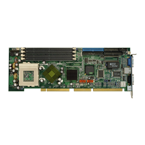
ROCKY-3702EV 's Layout... -
Page 12: Unpacking Precautions
Ground yourself to remove any static charge before touching your ROCKY-3702EV SBC. You can do it by using a grounded wrist strap at all times or by frequently touching any conducting materials that is connected to the ground. -
Page 13: Setting The Cpu Of Rocky-3702Ev
2.3 Setting the CPU of ROCKY-3702EV • JP3 : CPU FREQUENCY SETTING FREQUENCY 66MHz/100MHz Note: Intel Celeron CPU will auto-detect 66MHz/100MHz Intel Pentium III ( FC-PGA ) CPU will auto-detect 100MHz • JP8 : CPU MULTIPLIER SETTING Ratio 3.0 x 3.5 x... -
Page 14: Diskonchip™ Flash Disk
• JP12 : WDT Time-out Period PERIOD sec. sec. 10 sec. 20 sec. 110 sec. 220 sec. 2.5 DiskOnChip™ Flash Disk The DiskOnChip™ (DOC) Flash Disk Chip is produced by M- Systems. Customers don‘t need to install any extra software utility because DOC is 100% compatible to hard disk. -
Page 15: Chapter 3. Connection
Chapter 3. Connection This chapter describes how to connect peripherals, switches and indicators to the ROCKY-3702EV board. Floppy Disk Drive Connector ROCKY-3702EV board equipped with a 34-pin daisy-chain driver connector cable. • CN2 : FDD CONNECTOR PIN NO. DESCRIPTION PIN NO. -
Page 16: Pci E-Ide Disk Drive Connector
PCI E-IDE Disk Drive Connector You can attach four IDE (Integrated Device Electronics) hard disk drives to the ROCKY-3702EV IDE controller. CN1 (IDE 1) : Primary IDE Connector CN3 (IDE 2) : Secondary IDE Connector • CN1/CN3 : IDE Interface Connector PIN NO. -
Page 17: Parallel Port
Parallel Port This port is usually connected to a printer. The ROCKY-3702EV includes an on-board parallel port accessed through a 26-pin flat-cable connector CN4. • CN4 : Parallel Port Connector PIN NO. DESCRIPTION PIN NO. DESCRIPTION STROBE# DATA 0 DATA 1... -
Page 18: Keyboard/Mouse Connector
• CN11 : Serial Port 2x5 pin header Connector (COMB) Pin No. Description Pin No. Description Keyboard/Mouse Connector The ROCKY-3702EV provides one external keyboard, one external mouse and one PS/2 keyboard & mouse connectors. • CN8 : 5-pin Header External Keyboard Connector PIN NO. DESCRIPTION... -
Page 19: External Switches And Indicators
ATX POWER BUTTON ATX 5VSB ATX 5VSB ATX 5VSB 3.7 USB Port Connector The ROCKY-3702EV has two built-in USB ports for the future I/O bus expansion. • CN9: 2 USB Connectors Pin 1,3,5,7 for USB 0 Pin 2,4,6,8 for USB 1 PIN NO. -
Page 20: Irda Infrared Interface Port
3.8 IrDA Infrared Interface Port ROCKY-3702EV built-in IrDA port supports Serial Infrared (SIR) or Amplitude Shift Keyed IR (ASKIR) interface. If you want to use the IrDA port, you have to configure the SIR or ASKIR model in the BIOS’s Peripheral Setup’s COM2. Then the normal RS-232 COM2 will be disabled. -
Page 21: Lan Rj45 Connector
• CN5 : LED Connector for LAN LAN ACT. 3.11 Fan Connector The ROCKY-3702EV provides one CPU cooling fan connector and two system fan connectors. These connectors can supply 12V/500mA to the cooling fan. The connector has a “rotation” pin which supplies the fan’s rotation signal to the system, so the system BIOS knows the fan speed. -
Page 22: Chapter 4. Ami Bios Setup
Chapter 4. AMI BIOS Setup The ROCKY-3702EV uses the AMI PCI/ISA BIOS for system configuration. The AMI BIOS setup program is designed to provide maximum flexibility in configuring the system by offering various options which may be selected to meet end- users’... -
Page 23: Standard Cmos Setup
Standard CMOS Setup The standard CMOS Setup is used for basic hardware system configuration. The main function is for Date/Time setting and Floppy/Hard Disk setting. Please refer to the following screen. To set the Date, for example, press either the arrow or <Enter>... -
Page 24: Advanced Cmos Setup
Advanced CMOS Setup Advanced CMOS Setup is designed the purpose of tuning the ROCKY-3702EV board to operate in its best performance. For common operation use, customers don‘t have to change any of the default settings for the default setting is pre-set to run the most reliable operation. - Page 25 Boot Device > to define the sequence of boot drives after routine check up completes. If the 1 Boot Device fails, the BIOS will attempt to boot from the or the 3 device. The Optimal and Fail-Safe default settings are C:,A:,CDROM. Try Other Boot Devices >...
- Page 26 Primary Display > to define the type of display monitor of the system. The Absent option is for network file servers. Password Check > to define if a password is necessary or not for access to BIOS setup. Boot to OS/2 > if you are running the OS/2 operating system, this option must be set to yes.
-
Page 27: Advanced Chipset Setup
Advanced Chipset Setup This setup functions are working mostly for Chipset (Intel 440BX). These options are used to change the Chipset‘s registers. Please be careful while making changes to any default setting, otherwise the system will run unstably. Configure SDRAM Timing by SPD > Enabled will select predetermined optimal values of chipset parameters. - Page 28 DRAM Integrity Mode > to choose DRAM Integrity Mode; ECC/EC will enable the Error Checking and Correction DRAM integrity mode. DRAM Refresh Rate > to specify the timing for DRAM Refresh. Memory Hole : to specify the location of a memory hole in the CMOS RAM.
- Page 29 USB Passive Release > to specify whether or not PIIX4 is allowed to use Passive Release while transferring control data for USB transactions. PIIX4 Passive Release > Enabled will let the Passive Release mechanism encoded when CPU to PCI bus accesses.
-
Page 30: Power Management Setup
Power Management Setup Power Management/APM > to enable or disable the Advanced Power Management feature. Green PC Monitor Power State > to specify the power state of the monitor after the specified period of display- idle has ended. Video Power Down Mode > to specify the power state of the VESA VGA video subsystem after the specified period of display-idle has ended. - Page 31 Suspend Time Out (Minute) > to specify the length of the system-idle period while the system is in Standby state. After this period of time has ended, the system will go into Suspend state. Throttle Slow Clock Ratio > to specify the speed of system clock under power saving state.
-
Page 32: Pci / Plug And Play Setup
PCI / PLUG AND PLAY Setup The setup help user handles the ROCKY-3702EV board‘s PCI function. All PCI bus slots on the system use INTA#, thus all installed PCI slots must be set. Plug and Play Aware O/S > Yes or No When PNP OS is installed, interrupts will be reassigned by the OS when the setting is Yes. - Page 33 on each set of palette registers of every video devices, it must be set Enabled. Allocate IRQ to PCI VGA > to allocate IRQ to PCI VGA, choose Yes and vice versa. PCI IDE BusMaster > to include the BusMastering capability into the IDE Controller on the PCI.
-
Page 34: Peripheral Setup
4.7 Peripheral Setup This setup is working mostly on Multi-I/O Chip (W83977F). The options are used to change the Chipset‘s registers. Please be careful while making any changes to default setting as to meet your application need properly. The only special concern is Onboard Serial Port 2. - Page 35 IR Duplex Mode > to specify the mode of IR device that is connected to the IR port. IrDA Protocol > to specify the function mode if an IrDA mode is selected. Onboard Parallel Port > to specify the I/O port address of the parallel port.
-
Page 36: Hardware Monitor Setup
Hardware Monitor Setup There is a LM78 chip on your board which can monitor on board system voltage and fan speed. The voltage monitoring will cover +5V,+12V,-12V,and –5V. Note: Normal CPU Fan RPM is over than 5000 RPM. If your CPU Fan RPM is less than that figure, something is wrong and the CPU will be in overheat condition. -
Page 37: Change Supervisor / User Password
4.9 Change Supervisor / User Password This option sets a password that is used to protect your system and Setup Utility. Supervisor Password has higher priority than User Password. Once you setup the password, the system will always ask you to key-in password every time you enter the BIOS SETUP. -
Page 38: Auto-Detect Hard Disk
4.10 Auto-Detect Hard Disk This option detects the parameters of an IDE hard disk drive (HDD sector, cylinder, head, etc) automatically and will put the parameters into the Standard CMOS Setup screen. Up to 4 IDE drives can be detected and the parameters will be listed in the box. -
Page 39: Auto Configuration With Fail Save Settings
4.12 Auto Configuration with Fail Save Settings This option allows you to load the Fail Safe default settings when something happens to your computer results in the situation that it can no longer boot normally. These settings are not the most optimal settings but are the most stable settings. 4.13 Save Settings and Exit Select this option when you finish setting all the parameters and want to save them into the CMOS. -
Page 40: Chapter 5. E2 Key™ Function
Chapter 5. E Key™ Function The ROCKY-3702EV provides an outstanding E KEY™ function for system integrator. Based on the E KEY™, you are free to store the ID Code, Password or crucial data in the 1Kbit EEPROM. Because the EEPROM is nonvolatile memory, you don’t have to worry about losing these very important data. - Page 41 To start to use the function in a quick way, please refer to the included EKEYDEMO.C code before you start to operate. Please note that the E KEY™ function is based on the working of parallel port so you should enable ROCKY-3702EV’s parallel port, otherwise it will not work at all.
-
Page 42: Appendix A. Watch-Dog Timer
Appendix A. Watch-Dog Timer The WatchDog Timer is provided to ensure that standalone systems can always recover from catastrophic conditions that cause the CPU to crash. This condition may have occurred by external EMI or a software bug. When the CPU stops working correctly, hardware on the board will either perform a hardware reset (cold boot) or a Non-Maskable Interrupt (NMI) to bring the system back to a known state. -
Page 43: Appendix B. Atx Power Supply
ATX power supply but also has two types of power switch connection: 2.1. ROCKY-3702EV (through Power Button & +5VSB): Connect the ATX power supply switch to the pin 17 (power button) and pin 19 (+5VSB) of CN7 (multi panel) - Page 44 If you wish to turn off the power supply, please press the ATX power switch button down for about 4 sec. To turn ON system, simply push the button once. backplanes without connector. Refer to the following figures and follow the steps listed below: Please disconnect the AC cord of the Power Supply from the AC source to prevent sudden electric surge to the board.
- Page 45 The following ISBC have the ATX power control function: Rocky-P218A, Rocky-P228, Rocky-P238V, Rocky-P258BX, Rocky-548TX, Rocky-538TXV, Juki-710, PCISA-258EV, PCISA-358SV, Rocky-528AGP, Rocky-528AGP-100...
- Page 46 C. For backplanes with ATX power supply connector working as AT Mode Some SBC doesn’t come with ATX power ON/OFF function. In this case, you can control the ATX power supply through backplane’s PS ON connector. Refer to the figure below for the backplanes with ATX connector.
-
Page 47: Dma, Irq And 1 Mb Memory
Appendix C. DMA, IRQ and 1 MB Memory I/O Address Map DMA Channel Assignments: DMA Channel # Description Available Available Floppy Disk (8-bit transfer) Available Cascade for DMA controller 1 Available Available Available IRQ Mapping Chart IRQ0 System Timer IRQ8 RTC Clock IRQ1 Keyboard IRQ9... - Page 48 1st MB Memory Address Map Memory Address Description 00000-9FFFF System Board extension for ACPI BIOS A0000-C7FFF RAGE MOBILITY AGP F0000-FFFFF System Board extension for ACPI BIOS I/O Address Map I/O Address Range Description 000-00F DMA Controller #1 020-021 Interrupt Controller #1, Master 040-043 System Timer 060-064...
Need help?
Do you have a question about the Rocky-3702EV and is the answer not in the manual?
Questions and answers