Advertisement
Quick Links
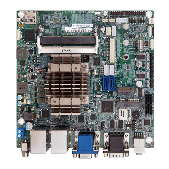
Mini-ITX SBC supports Intel® 14nm Atom™, Pentium® or Celeron®
on-board SoC with HDMI/LVDS/VGA, Dual PCIe GbE, USB 3.0,
PCIe Mini, M.2, SATA 6Gb/s, COM, Audio and RoHS
Quick Installation Guide
Package List
KINO-DAL package includes the following items:
1 x KINO-DAL single board computer with Heatsink
1 x SATA with power cable kit (P/N: 32801-000201-100-RS )
1 x I/O Shielding
1 x QIG (Quick Installation Guide)
KINO-DAL
Version 1.0
May 04, 2018.
©2018 Copyright by IEI Integration corp.
All rights reserved.
1
Advertisement

Related Manuals for IEI Technology KINO-DAL


Summary of Contents for IEI Technology KINO-DAL
- Page 1 Quick Installation Guide Version 1.0 May 04, 2018. Package List KINO-DAL package includes the following items: 1 x KINO-DAL single board computer with Heatsink 1 x SATA with power cable kit (P/N: 32801-000201-100-RS ) 1 x I/O Shielding ...
-
Page 2: Specifications
Specifications SoC: Intel® Atom® x7-E3950 on-board SoC (2.0GHz, quad-core) Intel® Atom® x5-E3940 on-board SoC (1.8GHz, quad-core) Intel® Atom® x5-E3930 on-board SoC (1.8GHz, dual-core) Intel® Pentium® N4200 on-board SoC (2.5GHz, quad-core) Intel® Celeron® N3350 on-board SoC (2.3GHz, dual-core) BIOS: AMI UEFI BIOS ... - Page 3 1 x USB 2.0 (180° Type-A) 4 x RS-232 (2x5 pin, P=2.00) 1 x KB/MS (1x6 pin) SMBus: 1 x SMBus (1x4 pin) I C: 1 x I C (1x4 pin) TPM: 1 x TPM (2x10 pin) ...
-
Page 4: Ordering Information
IEI Resource Download Center utility for the KINO-DAL are available on https://download.ieiworld.com IEI Resource Download Center. Type KINO-DAL and press Enter to find all the relevant software, utilities, and documentation. To install software from the downloaded ISO file, mount the file as a virtual drive to view its content. - Page 5 1.8GHz on-board SoC with HDMI/LVDS/VGA, Dual PCIe GbE, USB 3.0, PCIe Mini, M.2, SATA 6Gb/s, COM, Audio and RoHS, -40°C ~ 85°C KINO-DAL-E1W2-R10: Mini-ITX SBC supports Intel® 14nm dual-core Atom® x5-E3930 2.0GHz on-board SoC with HDMI/LVDS/VGA, Dual PCIe GbE, USB 3.0, PCIe Mini, M.2, SATA 6Gb/s, COM, Audio and RoHS, -40°C ~...
-
Page 6: Jumpers Setting And Connectors
Jumpers setting and connectors LABEL FUNCTION J_CMOS1 Clear CMOS Setup SW_A/T1 ATX or AT Power Select J_SATA1 M.2 SATA(M2_1) or SATA2 Select J_PW1 LCD Power Select F_PANEL1 F_PANEL Pin Header 2.54mm Pitch HDA1 Front Panel Audio Connector LCD Panel Type Select TPM1 LPC Interface for Port 80h Debug Tool CPU_FAN1... - Page 7 DIMM2 204-pin DDR3 SO-DIMM Channel B SATA1/SATA2 Standard 7Pin SATA Connector VGA1 Standard DB15 VGA Connector HDMI1 Standard HDMI Connector Standard RJ-45 and Dual USB 3.0 With LAN1_USB01_1/LAN2_USB23_1 LED Connector Standard Micro-SD Slot (Optional) MPCIE1 Standard Mini-PCIE Slot PCIE1 Standard PCIE *1 X Slot SIM1 Micro-SIM Card Slot (Optional) Chassis open Connector.
- Page 8 F_PANEL1: F_PANEL Pin Header 2.54mm Pitch PIN NO. DESCRIPTION PIN NO. DESCRIPTION PWR_LED+ SPKR+ PWR_LED- PWR_SW+ SPKR- PWR_SW- HDD_LED+ RESET_SW+ HDD_LED- RESET_SW- SW1: LCD Panel Type Select * ON=0, OFF=1 4-3-2-1 DESCRIPTION 0000 800x600 18bit 0001 1024x768 18bit 0010 1024x768 24bit 0011 1280x768 18bit 0100...
- Page 9 HDA1: Front Panel Audio Connector PIN NO. DESCRIPTION PIN NO. DESCRIPTION MIC2-L MIC2-R Pre-Sense# LINE2-R MIC2-JD LINE2-L LINE2-JD TPM1: LPC Interface for Port 80h Debug Tool PIN NO. DESCRIPTION PIN NO. DESCRIPTION Clock LFRAME# Serial IRQ LPC Reset LAD2- LAD3 LAD0 +3.3V LPC Reset...
- Page 10 SATA_PWR1/SATA_PWR2: SATA HDD Power Connector PIN NO. DESCRIPTION PIN NO. DESCRIPTION +12V J_SPI1/J_EC1: J_SPI1 Connector for System BIOS. J_EC1 Connector for EC ROM. PIN NO. DESCRIPTION PIN NO. DESCRIPTION +3.3V Clock MOSI MISO COM1/2 : Internal RS-232/RS-422/RS-485 Serial Port Connectors Mode RS-232 RS-422...
- Page 11 KB/MS1: PS2 Keyboard & Mouse Connector PIN NO. DESCRIPTION PIN NO. DESCRIPTION KB_DATA MS_DATA KB_CLK MS_CLK J_SMB1/JI2C1: SMBus / C Connector PIN NO. DESCRIPTION PIN NO. DESCRIPTION Clock Data LVDS1: LVDS Connector for LVDS LCD Panel PIN NO. DESCRIPTION PIN NO. DESCRIPTION A_DATA0- A_DATA1-...
- Page 12 INV11: LCD Inverter Connector PIN NO. DESCRIPTION PIN NO. DESCRIPTION LCD Adj +12V Backlight Enable PWR1: DC 12V System Power Input Connector PIN NO. DESCRIPTION PIN NO. DESCRIPTION +12V PS:Apollo Lake-I serial M/B Support DC Input 9V to 30V PWR2: DC 12V System Power Input Connector PIN NO.
- Page 13 DIO1: Digital I/O Connector PIN NO. DESCRIPTION PIN NO. DESCRIPTION D_OUT3 D_OUT2 D_OUT1 D_OUT0 D_IN3 D_IN2 D_IN1 D_IN0 BT1: RTC Battery connector PIN NO. DESCRIPTION PIN NO. DESCRIPTION RTC Battery+ RTC Battery- JLAN_LED1/JLAN_LED2: LAN1,LAN2 Active LED Pin header 2.0mm Pitch PIN NO.
- Page 14 Board Layout: Jumper and Connector Locations (Unit: mm)
Need help?
Do you have a question about the KINO-DAL and is the answer not in the manual?
Questions and answers