Table of Contents
Advertisement
Quick Links
Advertisement
Table of Contents

Related Manuals for IEI Technology KINO-CV-D25501


Summary of Contents for IEI Technology KINO-CV-D25501
- Page 1 KINO-CV-D25501/N26001 SBC MODEL: KINO-CV-D25501/N26001 Mini-ITX SBC with Intel® Atom™ D2550/N2600 Processor Up to 4.0 GB DDR3, VGA, HDMI, Dual LVDS, Dual GbE, SATA 3Gb/s, USB 3.0, microSD, PCIe Mini, RoHS User Manual Page i Rev. 1.04 – December 22, 2014...
- Page 2 KINO-CV-D25501/N26001 SBC Revision Date Version Changes December 22, 2014 1.04 Deleted SMBus connector information Modified Ethernet port information September 22, 2014 1.03 Modified Figure 3-1: Connector and Jumper Locations May 12, 2014 1.02 Modified Table 3-23: LAN1 Pinouts October 8, 2013 1.01...
- Page 3 KINO-CV-D25501/N26001 SBC Copyright COPYRIGHT NOTICE The information in this document is subject to change without prior notice in order to improve reliability, design and function and does not represent a commitment on the part of the manufacturer. In no event will the manufacturer be liable for direct, indirect, special, incidental, or consequential damages arising out of the use or inability to use the product or documentation, even if advised of the possibility of such damages.
-
Page 4: Table Of Contents
KINO-CV-D25501/N26001 SBC Table of Contents 1 INTRODUCTION......................1 1.1 I ......................2 NTRODUCTION 1.2 B ........................3 ENEFITS 1.3 F ........................3 EATURES 1.4 C ......................4 ONNECTORS 1.5 D ....................... 5 IMENSIONS 1.6 D ........................ 6 1.7 T ..................7... - Page 5 KINO-CV-D25501/N26001 SBC 3.2.11 PCIe Mini Card Slot..................27 3.2.12 Power Connector (9 V–28 V)................. 29 3.2.13 Power Button ....................30 3.2.14 RS-232 Serial Port Connectors (COM3, COM5, COM6) ......31 3.2.15 RS-422/485 Serial Port Connector (COM4)..........32 3.2.16 SATA Drive Connectors ................. 33 3.2.17 SATA Power Connectors ................
- Page 6 KINO-CV-D25501/N26001 SBC 4.7 I ............58 NTERNAL ERIPHERAL EVICE ONNECTIONS 4.7.1 SATA Drive Connection ................... 58 4.7.2 USB Cable Connection ..................59 4.7.3 Keyboard/Mouse Connector (Optional) ............60 4.8 S ..................61 OFTWARE NSTALLATION 5 BIOS ..........................64 5.1 I ......................
- Page 7 KINO-CV-D25501/N26001 SBC B TERMINOLOGY......................98 C DIGITAL I/O INTERFACE..................102 C.1 I ...................... 103 NTRODUCTION C.2 A 1................104 SSEMBLY ANGUAGE AMPLE C.3 A 2................104 SSEMBLY ANGUAGE AMPLE D HAZARDOUS MATERIALS DISCLOSURE ............105 D.1 H IPB P AZARDOUS...
- Page 8 KINO-CV-D25501/N26001 SBC List of Figures Figure 1-1: KINO-CV-D25501/N26001....................2 Figure 1-2: Connectors ........................4 Figure 1-3: Dimensions (mm) ......................5 Figure 1-4: Data Flow Diagram......................6 Figure 3-1: Connector and Jumper Locations................15 Figure 3-2: Battery Connector Location..................18 Figure 3-3: Digital I/O Connector Location ................19 Figure 3-4: Fan Connector Locations..................20...
- Page 9 KINO-CV-D25501/N26001 SBC Figure 3-26: HDMI Connector ......................43 Figure 3-27: 4-pin Power DIN Connection..................44 Figure 3-28: Serial Port Pinout Locations ..................44 Figure 3-29: VGA Connector .......................45 Figure 4-1: SO-DIMM Installation ....................49 Figure 4-2: PCIe Mini Card Installation..................50 Figure 4-3: AT/ATX Mode Selection Jumper Location..............52 Figure 4-4: Clear CMOS Jumper Location .................53...
- Page 10 KINO-CV-D25501/N26001 SBC List of Tables Table 1-1: Technical Specifications....................9 Table 2-1: Packing List.........................13 Table 2-2: Optional Items......................13 Table 3-1: Peripheral Interface Connectors ................17 Table 3-2: Rear Panel Connectors ....................17 Table 3-3: Battery Connector Pinouts ..................18 Table 3-4: Digital I/O Connector Pinouts..................19 Table 3-5: Fan Connector Pinouts ....................20...
- Page 11 KINO-CV-D25501/N26001 SBC Table 3-28: VGA Connector Pinouts...................45 Table 4-1: Jumpers ........................51 Table 4-2: AT/ATX Mode Selection .....................52 Table 4-3: Clear CMOS Jumper Settings..................53 Table 4-4: LVDS1 Voltage Selection ...................54 Table 4-5: LVDS2 Voltage Selection ...................54 Table 4-6: LVDS2 Resolution Selection ..................56 Table 4-7: PCIe Mini/mSATA Mode Selection ................56...
- Page 12 KINO-CV-D25501/N26001 SBC BIOS Menus BIOS Menu 1: Main ........................67 BIOS Menu 2: Advanced ......................68 BIOS Menu 3: ACPI Configuration ....................69 BIOS Menu 4: RTC Wake Settings ....................70 BIOS Menu 5: CPU Configuration ....................71 BIOS Menu 6: IDE Configuration....................73 BIOS Menu 7: USB Configuration ....................74 BIOS Menu 8: Super IO Configuration..................75...
-
Page 13: Introduction
KINO-CV-D25501/N26001 SBC Chapter Introduction Page 1... -
Page 14: Introduction
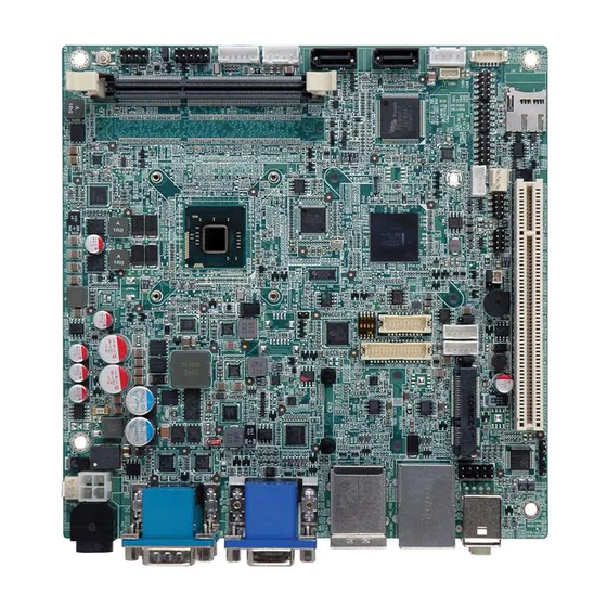
1.1 Introduction Figure 1-1: KINO-CV-D25501/N26001 The KINO-CV-D25501/N26001 is a Mini-ITX SBC with a Intel® Atom™ processor D2550 or N2600. The KINO-CV-D25501/N26001 is designed for fanless operation. The low power CPUs don't require active cooling and stay within specified heat range using the included heatsink. -
Page 15: Benefits
Some of the KINO-CV-D25501/N26001 motherboard benefits include: Low power consumption Wide range of I/O interfaces Dual display support 1.3 Features Some of the KINO-CV-D25501/N26001 motherboard features are listed below: Mini-ITX form factor Fanless design RoHS compliant ... -
Page 16: Connectors
KINO-CV-D25501/N26001 SBC 1.4 Connectors The connectors on the KINO-CV-D25501/N26001 are shown in the figure below. Figure 1-2: Connectors Page 4... -
Page 17: Dimensions
KINO-CV-D25501/N26001 SBC 1.5 Dimensions The main dimensions of the KINO-CV-D25501/N26001 are shown in the diagram below. Figure 1-3: Dimensions (mm) Page 5... -
Page 18: Data Flow
KINO-CV-D25501/N26001 SBC 1.6 Data Flow Figure 1-4 shows the data flow between the system chipset, the CPU and other components installed on the motherboard. Figure 1-4: Data Flow Diagram Page 6... -
Page 19: Technical Specifications
KINO-CV-D25501/N26001 SBC 1.7 Technical Specifications KINO-CV-D25501/N26001 technical specifications are listed in Table 1-1. Specification KINO-CV-D25501/N26001 Mini-ITX Form Factor 1.86 GHz Intel® Atom™ D2550 dual-core CPU On-board CPU 1.60 GHz Intel® Atom™ N2600 dual-core CPU 1.86 GHz Intel® Atom™ N2800 dual-core CPU (optional) Intel®... - Page 20 KINO-CV-D25501/N26001 SBC I/O Interface Connectors One Analog CRT (up to 2048 x 1536 @ 75 Hz) Display Output Ports (Dual Display Supported) One HDMI (up to 1920 x 1200 @ 60 Hz) One LVDS 1: D2550: 24-bit single-channel LVDS up to 1440 x 900 ...
-
Page 21: Table 1-1: Technical Specifications
KINO-CV-D25501/N26001 SBC D2550: -20ºC–60ºC with free air; -20ºC–70ºC with force air Operating Temperature N2600 and N2800: -20ºC–70ºC with free air; -20ºC–75ºC with force D2550: -30ºC–80ºC Storage Temperature N2600 and N2800: -30ºC–85ºC 5%–95% (non-condensing) Operating Humidity Physical Specifications Dimensions 170 mm x 170 mm... -
Page 22: Packing List
KINO-CV-D25501/N26001 SBC Chapter Packing List Page 10... -
Page 23: Anti-Static Precautions
Only handle the edges of the PCB: Don't touch the surface of the motherboard. Hold the motherboard by the edges when handling. 2.2 Unpacking Precautions When the KINO-CV-D25501/N26001 is unpacked, please do the following: Follow the antistatic guidelines above. -
Page 24: Packing List
If any of the components listed in the checklist below are missing, do not proceed with the installation. Contact the IEI reseller or vendor the KINO-CV-D25501/N26001 was purchased from or contact an IEI sales representative directly by sending an email to sales@ieiworld.com... -
Page 25: Optional Items
KINO-CV-D25501/N26001 SBC Quantity Item and Part Number Image One Key Recovery CD Quick installation guide Table 2-1: Packing List 2.4 Optional Items These optional items are available. Item and Part Number Image RS-422/485 cable (P/N: 32205-003800-300-RS) KB/MS PS/2 Y-cable (P/N: 32000-023800-RS) -
Page 26: Connector Pinouts
KINO-CV-D25501/N26001 SBC Chapter Connector Pinouts Page 14... -
Page 27: Peripheral Interface Connectors
KINO-CV-D25501/N26001 SBC 3.1 Peripheral Interface Connectors Section 3.1.1 shows peripheral interface connector locations. Section 3.1.2 lists all the peripheral interface connectors seen in Section 3.1.1. 3.1.1 Layout The figure below shows the on-board peripheral connectors, rear panel peripheral connectors and on-board jumpers. -
Page 28: Peripheral Interface Connectors
KINO-CV-D25501/N26001 SBC 3.1.2 Peripheral Interface Connectors The table below shows a list of the peripheral interface connectors on the KINO-CV-D25501/N26001. Detailed descriptions of these connectors can be found below. Connector Type Label Battery connector 2-pin wafer Digital I/O connector 10-pin header... -
Page 29: External Interface Panel Connectors
8-pin header USB2, USB3 Table 3-1: Peripheral Interface Connectors 3.1.3 External Interface Panel Connectors The table below lists the rear panel connectors on the KINO-CV-D25501/N26001. Detailed descriptions of these connectors can be found in a later section. Connector Type Label... -
Page 30: Battery Connector
KINO-CV-D25501/N26001 SBC 3.2.1 Battery Connector CAUTION: Risk of explosion if battery is replaced by an incorrect type. Only certified engineers should replace the on-board battery. Dispose of used batteries according to instructions and local regulations. CN Label: CN Type: 2-pin wafer... -
Page 31: Digital I/O Connector
KINO-CV-D25501/N26001 SBC 3.2.2 Digital I/O Connector CN Label: DIO1 10-pin header CN Type: CN Location: See Figure 3-3 CN Pinouts: See Table 3-4 The digital I/O connector provides programmable input and output for external devices. The digital I/O provides 4-bit output and 4-bit input. -
Page 32: Fan Connectors
KINO-CV-D25501/N26001 SBC 3.2.3 Fan Connectors CN Label: CPU_FAN1, SYS_FAN1 3-pin wafer CN Type: CN Location: See Figure 3-4 CN Pinouts: See Table 3-5 The fan connector attaches to a cooling fan. Figure 3-4: Fan Connector Locations Description FANIO1 +12V (PWM) Table 3-5: Fan Connector Pinouts 3.2.4 Front Audio Connector... -
Page 33: Front Panel Connector
KINO-CV-D25501/N26001 SBC This connector connects to speaker, microphone and audio input connectors on the front panel. Figure 3-5: Front Audio Connector Location Description Description MIC_L MIC_R Audio Detect LINE2-R Jack Detection LINE2-L Table 3-6: Front Audio Connector Pinouts 3.2.5 Front Panel Connector... -
Page 34: Keyboard/Mouse Connector
KINO-CV-D25501/N26001 SBC Figure 3-6: Front Panel Connector Location Description Description Power PWRBTSW- Power Button GROUND GROUND SYSRST- Reset -HDLED Ground Table 3-7: Front Panel Connector Pinouts 3.2.6 Keyboard/Mouse Connector CN Label: KB_MS1 CN Type: 6-pin wafer CN Location: See Figure 3-7... -
Page 35: Lvds Connector (Lvds1)
KINO-CV-D25501/N26001 SBC Figure 3-7: Keyboard/Mouse Connector Location Description Mouse Data Mouse Clock Keyboard Data Keyboard Clock Table 3-8: Keyboard/Mouse Connector Pinouts 3.2.7 LVDS Connector (LVDS1) CN Label: LVDS1 20-pin crimp CN Type: CN Location: See Figure 3-8 CN Pinouts: See Table 3-9 The LVDS connector is for an LCD panel connected to the board. -
Page 36: Lvds Connector (Lvds2)
KINO-CV-D25501/N26001 SBC Figure 3-8: LVDS1 Connector Location Description Description LVDS_DATA0 LVDS_DATA0# LVDS_DATA1 LVDS_DATA1# LVDS_DATA2 LVDS_DATA2# LVDS_CLK LVDS_CLK# LDDC_DATA LDDC_CLK VCC_LCD VCC_LCD VCC_LCD VCC_LCD Table 3-9: LVDS1 Connector Pinouts 3.2.8 LVDS Connector (LVDS2) CN Label: LVDS2 30-pin crimp CN Type: CN Location:... -
Page 37: Figure 3-9: Lvds2 Connector Location
KINO-CV-D25501/N26001 SBC Figure 3-9: LVDS2 Connector Location Description Description LVDS_DATA0 LVDS_DATA0# LVDS_DATA1 LVDS_DATA1# LVDS_DATA2 LVDS_DATA2# LVDS_CLK1 LVDS_CLK1# LVDS_DATA3 LVDS_DATA3# LVDS_DATA4 LVDS_DATA4# LVDS_DATA5 LVDS_DATA5# LVDS_DATA6 LVDS_DATA6# LVDS_CLK2 LVDS_CLK2# LVDS_DATA7 LVDS_DATA7# VCC_LCD VCC_LCD VCC_LCD VCC_LCD Table 3-10: LVDS2 Connector Pinouts Page 25... -
Page 38: Lvds Backlight Connectors
KINO-CV-D25501/N26001 SBC 3.2.9 LVDS Backlight Connectors CN Label: INV1, INV2 5-pin wafer CN Type: CN Location: See Figure 3-10 CN Pinouts: See Table 3-11 The backlight inverter connectors provide power to LCD panels. Figure 3-10: LVDS Backlight Inverter Connectors Description... -
Page 39: Pcie Mini Card Slot
KINO-CV-D25501/N26001 SBC CN Pinouts: See Table 3-12 A microSD card can be installed in the microSD card slot. Figure 3-11: microSD Slot Location Description DAT2 DAT3 VSS1 DAT0 DAT1 Table 3-12: microSD Slot Connector Pinouts 3.2.11 PCIe Mini Card Slot... -
Page 40: Figure 3-12: Pcie Mini Card Slot Location
KINO-CV-D25501/N26001 SBC The PCIe mini card slot enables a PCIe mini card expansion module to be connected to the board. Cards supported include among others wireless LAN (WLAN) cards and mSATA cards. NOTE: If the PCIe Mini slot is installed with an mSATA card, the SATA2 connector will be disabled. -
Page 41: Power Connector (9 V-28 V)
KINO-CV-D25501/N26001 SBC Description Description PCIRST# PCIE_RXN VCC3 PCIE_RXP 1.5V SMBCLK PCIE_TXN SMBDATA PCIE_TXP USBD- USBD+ VCC3 VCC3 1.5V M-SATA Detect VCC3 Table 3-13: PCIe Mini Card Slot Pinouts 3.2.12 Power Connector (9 V–28 V) CN Label: CN Type: 4-pin connector... -
Page 42: Power Button
KINO-CV-D25501/N26001 SBC Figure 3-13: ATX Power Connector Location Description Description Ground Ground Power Power Table 3-14: Power Connector Pinouts 3.2.13 Power Button CN Label: PWR_SW1 CN Type: Push button See Figure 3-14 CN Location: It is an on-board power button. Push the power button to turn on the system. -
Page 43: Serial Port Connectors (Com3, Com5, Com6)
KINO-CV-D25501/N26001 SBC 3.2.14 RS-232 Serial Port Connectors (COM3, COM5, COM6) CN Label: COM3, COM5, COM6 10-pin header CN Type: CN Location: See Figure 3-15 CN Pinouts: See Table 3-15 The 10-pin serial port connectors provide three RS-232 serial communications channels. -
Page 44: Rs-422/485 Serial Port Connector (Com4)
KINO-CV-D25501/N26001 SBC 3.2.15 RS-422/485 Serial Port Connector (COM4) CN Label: COM4 4-pin wafer CN Type: CN Location: See Figure 3-16 CN Pinouts: See Table 3-16 This connector provides RS-422 or RS-485 communications. Figure 3-16: RS-422/485 Serial Port Connector Location Description... -
Page 45: Sata Drive Connectors
KINO-CV-D25501/N26001 SBC RS-422 Pinouts RS-485 Pinouts Table 3-17: D-sub 9 RS-422/485 Pinouts 3.2.16 SATA Drive Connectors CN Label: SATA1, SATA2 CN Type: 7-pin SATA drive connectors See Figure 3-17 CN Location: CN Pinouts: See Table 3-18 The SATA connectors connect to SATA hard drives or optical drives with data transfer speeds as high as 3Gb/s. -
Page 46: Sata Power Connectors
KINO-CV-D25501/N26001 SBC Figure 3-17: SATA Drive Connector Location Description Table 3-18: SATA Drive Connector Pinouts 3.2.17 SATA Power Connectors CN Label: SATA_PWR1, SATA_PWR2 CN Type: 4-pin wafer CN Location: See Figure 3-18 CN Pinouts: See Table 3-19 Use the SATA Power Connector to connect to SATA device power connections. -
Page 47: So-Dimm Connector
KINO-CV-D25501/N26001 SBC Figure 3-18: SATA Power Connector Locations Description Table 3-19: SATA Power Connector Pinouts 3.2.18 SO-DIMM Connector CN Label: DIMM1 CN Type: 204-pin DDR3 SO-DIMM connector CN Location: See Figure 3-19 The SO-DIMM connector is for installing memory on the system. -
Page 48: Spdif Connector
KINO-CV-D25501/N26001 SBC Figure 3-19: SO-DIMM Connector Location 3.2.19 SPDIF Connector CN Label: SPDIF1 CN Type: 5-pin header CN Location: See Figure 3-20 CN Pinouts: See Table 3-20 Use the SPDIF connector to connect digital audio devices to the system. Figure 3-20: SPDIF Connector Location... -
Page 49: Spi Flash Connector
KINO-CV-D25501/N26001 SBC Description VCC AUDIO SPDIF OUT SPDIF IN Table 3-20: SPDIF Connector Pinouts 3.2.20 SPI Flash Connector CN Label: JSPI1 CN Type: 6-pin header CN Location: See Figure 3-21 CN Pinouts: See Table 3-21 The 6-pin SPI Flash connector is used to flash the BIOS. -
Page 50: Usb 2.0 Connectors
KINO-CV-D25501/N26001 SBC 3.2.21 USB 2.0 Connectors CN Label: USB2, USB3 8-pin header CN Type: CN Location: See Figure 3-22 CN Pinouts: See Table 3-22 The USB header can connect to two USB devices. Figure 3-22: USB Connector Locations Description Description... -
Page 51: External Interface Connectors
KINO-CV-D25501/N26001 SBC 3.3 External Interface Connectors Figure 3-23 shows the KINO-CV-D25501/N26001 motherboard external interface connectors. The KINO-CV-D25501/N26001 on-board external interface connectors are shown in Figure 3-23. Figure 3-23: External Interface Connectors 3.3.1 Audio Connector CN Label: AUDIO_CV1 CN Type: Audio jacks... -
Page 52: Ethernet And Usb 2.0 Combo Connector
KINO-CV-D25501/N26001 SBC Figure 3-24: Audio Connector 3.3.2 Ethernet and USB 2.0 Combo Connector CN Label: LAN1_USB1 CN Type: RJ-45 and USB 2.0 connector See Figure 3-23 CN Location: CN Pinouts: See Table 3-23 and Table 3-25 The LAN connector connects to a local network. -
Page 53: Ethernet And Usb 3.0 Combo Connector
KINO-CV-D25501/N26001 SBC Description Description on: linked off: 10 Mb/s blinking: data is being sent/received green: 100 Mb/s orange: 1000 Mb/s Table 3-24: Connector LEDs The USB 2.0 connector can be connected to a USB 2.0 device. DESCRIPTION Data- Data+ Table 3-25: USB Port Pinouts 3.3.3 Ethernet and USB 3.0 Combo Connector... -
Page 54: Hdmi Connector
KINO-CV-D25501/N26001 SBC Figure 3-26: Ethernet Connector Description Description on: linked off: 10 Mb/s blinking: data is being sent/received green: 100 Mb/s orange: 1000 Mb/s Table 3-27: Connector LEDs The USB 3.0 connector can be connected to a USB device. Description... -
Page 55: Power Connector (9 V-28 V, Power Adapter)
KINO-CV-D25501/N26001 SBC Description Description HDMI_DATA2 HDMI_DATA2# HDMI_SCL HDMI_DATA1 HDMI_SDA HDMI_DATA1# HDMI_DATA0 HDMI_HPD HDMI_GND HDMI_DATA0# HDMI_GND HDMI_CLK HDMI_GND HDMI_GND HDMI_CLK# Table 3-29: HDMI Connector Pinouts Figure 3-27: HDMI Connector 3.3.5 Power Connector (9 V–28 V, Power Adapter) CN Label: PWR1 CN Type:... -
Page 56: Serial Port Connectors (Com1, Com2)
KINO-CV-D25501/N26001 SBC Figure 3-28: 4-pin Power DIN Connection 3.3.6 Serial Port Connectors (COM1, COM2) CN Label: COM1 CN Type: D-sub 9 Male connector See Figure 3-23 CN Location: CN Pinouts: See Table 3-30 and Figure 3-29 The RS-232 serial connector provides serial connection in the RS-232 mode. -
Page 57: Vga Connector
KINO-CV-D25501/N26001 SBC 3.3.7 VGA Connector NOTE: Due to Intel® GMA driver limitation, the monitor connected to the VGA connector may not have signal to it after restarting from the graphics driver installation. To solve this problem, press the Ctrl+Alt+F1 hotkey to switch the screen to CRT mode. -
Page 58: Installation
KINO-CV-D25501/N26001 SBC Chapter Installation Page 46... -
Page 59: Anti-Static Precautions
Electrostatic discharge (ESD) can cause serious damage to electronic components, including the KINO-CV-D25501/N26001. Dry climates are especially susceptible to ESD. It is therefore critical to strictly adhere to the following anti-static precautions whenever the KINO-CV-D25501/N26001, or any other electrical component, is handled. -
Page 60: Installation Considerations
4.2 Installation Considerations NOTE: The following installation notices and installation considerations should be read and understood before the KINO-CV-D25501/N26001 is installed. All installation notices pertaining to the installation of KINO-CV-D25501/N26001 should be strictly adhered to. Failing to adhere to these precautions may lead to severe damage of the KINO-CV-D25501/N26001 and injury to the person installing the motherboard. -
Page 61: So-Dimm Installation
KINO-CV-D25501/N26001 SBC Before and during the installation of the KINO-CV-D25501/N26001 DO NOT: DO NOT remove any of the stickers on the PCB board. These stickers are required for warranty validation. DO NOT use the product before verifying all the cables and power connectors are properly connected. -
Page 62: Pcie Mini Card Installation
KINO-CV-D25501/N26001 SBC Step 4: Removing a SO-DIMM. To remove a SO-DIMM, push both handles outward. The memory module is ejected by a mechanism in the socket.Step 0: 4.4 PCIe Mini Card Installation To install the PCIe Mini card, please refer to the diagram and instructions below. -
Page 63: Jumper Settings
To CLOSE/SHORT a jumper means connecting the pins of the jumper with the plastic clip and to OPEN a jumper means removing the plastic clip from a jumper. Before the KINO-CV-D25501/N26001 is installed in the system, the jumpers must be set accordance with desired configuration. -
Page 64: Clear Cmos Jumper
Jumper Location: See Figure 4-3 Set both of the jumpers select AT or ATX power mode for the KINO-CV-D25501/N26001. AT power mode limits the system to on/off. ATX allows the system to use various power saving states and enter a standby state, so the system can be turned on remotely over a network. -
Page 65: Lvds1 Voltage Selection
KINO-CV-D25501/N26001 SBC use the jumper cap to close pins 2 and 3 for a few seconds then reinstall the jumper clip back to pins 1 and 2. If the “CMOS Settings Wrong” message is displayed during the boot up process, the fault may be corrected by pressing the F1 to enter the CMOS Setup menu. -
Page 66: Lvds2 Voltage Selection
KINO-CV-D25501/N26001 SBC Jumper Location: See Figure 4-5 The JP4 jumper selects the voltage of the LVDS1 connector. Description Short 1-2 +3.3 V (Default) Short 2-3 +5 V Table 4-4: LVDS1 Voltage Selection Figure 4-5: LVDS1 Voltage Selection Jumper Location 4.5.4 LVDS2 Voltage Selection... -
Page 67: Lvds2 Resolution Selection
KINO-CV-D25501/N26001 SBC Figure 4-6: LVDS2 Voltage Selection Jumper Location 4.5.5 LVDS2 Resolution Selection Jumper Label: Jumper Type: DIP switch Jumper Settings: See Table 4-6 See Figure 4-7 Jumper Location: The SW1 switch selects the resolution of the LCD panel connected to the LVDS2 connector. -
Page 68: Pcie Mini/Msata Mode Selection
KINO-CV-D25501/N26001 SBC 1010 1440 x 1050 @ 60Hz 24-bit Dual 1011 1600 x 900 @ 60Hz 24-bit Dual 1100 1680 x 1050 @ 60Hz 24-bit Dual 1101 1600 x 1200 @ 60Hz 24-bit Dual 1110 1920 x 1080 @ 60Hz... -
Page 69: Chassis Installation
The chassis should have fans and vents as necessary to keep things cool. The KINO-CV-D25501/N26001 must be installed in a chassis with ventilation holes on the sides allowing airflow to travel through the heat sink surface. In a system with an individual power supply unit, the cooling fan of a power supply can also help generate airflow through the board surface. -
Page 70: Internal Peripheral Device Connections
This section outlines the installation of peripheral devices to the onboard connectors. 4.7.1 SATA Drive Connection The KINO-CV-D25501/N26001 is shipped with two SATA drive cable. To connect the SATA drive to the connector, please follow the steps below. Step 1: Locate the SATA connector and the SATA power connector. -
Page 71: Usb Cable Connection
KINO-CV-D25501/N26001 SBC 4.7.2 USB Cable Connection The KINO-CV-D25501/N26001 is shipped with a dual port USB 2.0 cable. To connect the USB cable connector, please follow the steps below. Step 1: Locate the connectors. The locations of the USB connectors are shown in Chapter 3. -
Page 72: Keyboard/Mouse Connector (Optional)
The KINO-CV-D25501/N26001 can be shipped with a keyboard/mouse Y-cable connector. The keyboard/mouse Y-cable connector connects to a keyboard/mouse connector on the KINO-CV-D25501/N26001 and branches into two cables that are each connected to a PS/2 connector, one for a mouse and one for a keyboard. To connect the keyboard/mouse Y-cable connector, please follow the steps below. -
Page 73: Software Installation
Please make sure the keyboard and mouse are connected to the correct PS/2 connector. 4.8 Software Installation All the drivers for the KINO-CV-D25501/N26001 are on the CD that came with the system. To install the drivers, please follow the steps below. Step 6: Insert the CD into a CD drive connected to the system. -
Page 74: Figure 4-18: Introduction Screen
KINO-CV-D25501/N26001 SBC Figure 4-12: Introduction Screen Step 8: Click KINO-CV-D25501/N26001. Step 9: A new screen with a list of available drivers appears (Figure 4-13). Figure 4-13: Available Drivers Step 10: Install all of the necessary drivers in this menu. S t e p 0 :... - Page 75 KINO-CV-D25501/N26001 SBC NOTE: Due to Intel® GMA driver limitation, the monitor connected to the VGA connector may not have signal to it after restarting from the graphics driver installation. To solve this problem, press the Ctrl+Alt+F1 hotkey to switch the screen to CRT mode.
-
Page 76: Bios
KINO-CV-D25501/N26001 SBC Chapter BIOS Page 64... -
Page 77: Introduction
KINO-CV-D25501/N26001 SBC 5.1 Introduction The BIOS is programmed onto the BIOS chip. The BIOS setup program allows changes to certain system settings. This chapter outlines the options that can be changed. NOTE: Some of the BIOS options may vary throughout the life cycle of the product and are subject to change without prior notice. -
Page 78: Getting Help
KINO-CV-D25501/N26001 SBC Function Increase the numeric value or make changes Decrease the numeric value or make changes Page up Move to the next page Page down Move to the previous page Main Menu – Quit and do not save changes into CMOS... -
Page 79: Main
KINO-CV-D25501/N26001 SBC Security – Sets User and Supervisor Passwords. Save & Exit – Selects exit options and loads default settings The following sections completely describe the configuration options found in the menu items at the top of the BIOS screen and listed above. -
Page 80: Advanced
KINO-CV-D25501/N26001 SBC System Date [xx/xx/xx] Use the System Date option to set the system date. Manually enter the day, month and year. System Time [xx:xx:xx] Use the System Time option to set the system time. Manually enter the hours, minutes and seconds. -
Page 81: Acpi Configuration
KINO-CV-D25501/N26001 SBC 5.3.1 ACPI Configuration The ACPI Configuration menu (BIOS Menu 3) configures the Advanced Configuration and Power Interface (ACPI) options. Aptio Setup Utility – Copyright (C) 2011 American Megatrends, Inc. Advanced ACPI Settings Select the highest ACPI sleep state the system... -
Page 82: Rtc Wake Settings
KINO-CV-D25501/N26001 SBC 5.3.2 RTC Wake Settings The RTC Wake Settings menu (BIOS Menu 4) configures RTC wake event. Aptio Setup Utility – Copyright (C) 2011 American Megatrends, Inc. Advanced Wake system with Fixed Time [Disabled] Enable or disable System wake on alarm event. When... -
Page 83: Cpu Configuration
KINO-CV-D25501/N26001 SBC Enabled If selected, the following appears with values that can be selected: *Wake up every day *Wake up date *Wake up hour *Wake up minute *Wake up second After setting the alarm, the computer turns itself on from a suspend state when the alarm goes off. - Page 84 KINO-CV-D25501/N26001 SBC The CPU Configuration menu (BIOS Menu 5) lists the following CPU details: Processor Type: Lists the brand name of the CPU being used EMT64: Indicates if the EM64T is supported by the CPU. Processor Speed: Lists the CPU processing speed ...
-
Page 85: Ide Configuration
KINO-CV-D25501/N26001 SBC 5.3.4 IDE Configuration Use the IDE Configuration menu (BIOS Menu 6) to change and/or set the configuration of the IDE devices installed in the system. Aptio Setup Utility – Copyright (C) 2011 American Megatrends, Inc. Advanced SATA Port0... -
Page 86: Usb Configuration
KINO-CV-D25501/N26001 SBC 5.3.5 USB Configuration Use the USB Configuration menu (BIOS Menu 7) to read USB configuration information and configure the USB settings. Aptio Setup Utility – Copyright (C) 2011 American Megatrends, Inc. Advanced USB Configuration Enables Legacy USB support. AUTO option... -
Page 87: F81866 Super Io Configuration
KINO-CV-D25501/N26001 SBC Enabled Legacy USB support enabled EFAULT Legacy USB support disabled Disabled Auto Legacy USB support disabled if no USB devices are connected USB3.0 Support [Enabled] Use the USB3.0 Support BIOS option to enable or disable the USB 3.0 controller ... -
Page 88: Serial Port N Configuration
KINO-CV-D25501/N26001 SBC 5.3.6.1 Serial Port n Configuration Use the Serial Port n Configuration menu (BIOS Menu 9) to configure the serial port n. Aptio Setup Utility – Copyright (C) 2011 American Megatrends, Inc. Advanced Serial Port 1 Configuration Enable or Disable Serial... - Page 89 KINO-CV-D25501/N26001 SBC IO=3F8h; Serial Port I/O port address is 3E8h and the interrupt IRQ=3, 4 address is IRQ3, 4 Serial Port I/O port address is 2F8h and the interrupt IO=2F8h; address is IRQ3, 4 IRQ=3, 4 IO=3E8h;...
- Page 90 KINO-CV-D25501/N26001 SBC IO=2E8h; Serial Port I/O port address is 2E8h and the interrupt IRQ=3, 4 address is IRQ3, 4 5.3.6.1.3 Serial Port 3 Configuration Serial Port [Enabled] Use the Serial Port option to enable or disable the serial port.
- Page 91 KINO-CV-D25501/N26001 SBC 5.3.6.1.4 Serial Port 4 Configuration Serial Port [Enabled] Use the Serial Port option to enable or disable the serial port. Disabled Disable the serial port Enable the serial port Enabled EFAULT Change Settings [Auto] Use the Change Settings option to change the serial port IO port address and interrupt address.
- Page 92 KINO-CV-D25501/N26001 SBC 5.3.6.1.5 Serial Port 5 Configuration Serial Port [Enabled] Use the Serial Port option to enable or disable the serial port. Disabled Disable the serial port Enable the serial port Enabled EFAULT Change Settings [Auto] Use the Change Settings option to change the serial port IO port address and interrupt address.
- Page 93 KINO-CV-D25501/N26001 SBC 5.3.6.1.6 Serial Port 6 Configuration Serial Port [Enabled] Use the Serial Port option to enable or disable the serial port. Disabled Disable the serial port Enable the serial port Enabled EFAULT Change Settings [Auto] Use the Change Settings option to change the serial port IO port address and interrupt address.
-
Page 94: F81866 H/W Monitor
KINO-CV-D25501/N26001 SBC 5.3.7 F81866 H/W Monitor The F8186 H/W Monitor menu (BIOS Menu 10) shows the operating temperature, fan speeds and system voltages. Aptio Setup Utility – Copyright (C) 2011 American Megatrends, Inc. Advanced PC Health Status Smart Fan Mode Select >... -
Page 95: Smart Fan Mode Configuration
KINO-CV-D25501/N26001 SBC VSB3V VBAT 5.3.7.1 Smart Fan Mode Configuration Use the Smart Fan Mode Configuration submenu (BIOS Menu 11) to configure the smart fan temperature and speed settings. Aptio Setup Utility – Copyright (C) 2011 American Megatrends, Inc. Advanced Smart Fan Mode Configuration... -
Page 96: Serial Port Console Redirection
KINO-CV-D25501/N26001 SBC SYS_FAN1 Smart Fan Control [Auto Duty-Cycle Mode] Use the SYS_FAN1 Smart Fan Control option to configure the System Smart Fan (SYS_FAN1). Manual Duty The fan spins at the speed set in Manual by Duty Mode Cycle settings ... -
Page 97: Iei Feature
KINO-CV-D25501/N26001 SBC Aptio Setup Utility – Copyright (C) 2011 American Megatrends, Inc. Advanced COM1 Console Redirection Console Redirection [Disabled] Enable or Disable > Console Redirection Settings COM2 Console Redirection [Disabled] > Console Redirection Settings COM3 Console Redirection [Disabled] > Console Redirection Settings --------------------- : Select Screen... -
Page 98: Chipset
KINO-CV-D25501/N26001 SBC Aptio Setup Utility – Copyright (C) 2011 American Megatrends, Inc. Advanced iEi Feature Auto Recovery Function Reboot and recover Auto Recovery Function [Disabled] system automatically within 10 min, when OS crashes. Please install Auto Recovery API service before enabling... -
Page 99: Host Bridge
KINO-CV-D25501/N26001 SBC Aptio Setup Utility – Copyright (C) 2011 American Megatrends, Inc. Main Advanced Chipset Boot Security Save & Exit > Host Bridge Host Bridge Parameters > South Bridge --------------------- : Select Screen : Select Item Enter Select General Help... -
Page 100: Intel Igd Configuration
KINO-CV-D25501/N26001 SBC 5.4.1.1 Intel IGD Configuration Use the Intel IGD Configuration menu to configure the video device connected to the system. Aptio Setup Utility – Copyright (C) 2011 American Megatrends, Inc. Chipset Intel IGD Configuration Select the Video Device IGFX - Boot Type... -
Page 101: South Bridge
KINO-CV-D25501/N26001 SBC 640x480 LVDS 800x600 LVDS EFAULT 1024x768 LVDS 1280x1024 LVDS 1366x768 LVDS 1224x600 LVDS 1280x800 LVDS Backlight Control [Inverted] Use the Backlight Control option to select the backlight control mode. ... - Page 102 KINO-CV-D25501/N26001 SBC Aptio Setup Utility – Copyright (C) 2011 American Megatrends, Inc. Chipset Auto Power Button Status [Enabled] Enabled to reduce power consumption in system Power Saving Function(ERP) [Disabled] off state. Set Spread Spectrum function [Disabled] --------------------- : Select Screen ...
-
Page 103: Boot
KINO-CV-D25501/N26001 SBC 5.5 Boot Use the Boot menu (BIOS Menu 18) to configure system boot options. Aptio Setup Utility – Copyright (C) 2011 American Megatrends, Inc. Main Advanced Chipset Boot Security Save & Exit Boot Configuration Select the keyboard Bootup NumLock State... - Page 104 KINO-CV-D25501/N26001 SBC Quiet Boot [Enabled] Use the Quiet Boot BIOS option to select the screen display when the system boots. Normal POST messages displayed Disabled Enabled OEM Logo displayed instead of POST messages EFAULT Launch PXE OpROM [Disabled] Use the Launch PXE OpROM option to enable or disable boot option for legacy network devices.
-
Page 105: Security
KINO-CV-D25501/N26001 SBC 5.6 Security Use the Security menu (BIOS Menu 19) to set system and user passwords. Aptio Setup Utility – Copyright (C) 2011 American Megatrends, Inc. Main Advanced Chipset Boot Security Save & Exit Password Description Set Setup Administrator Password If ONLY the Administrator’s password is set,... - Page 106 KINO-CV-D25501/N26001 SBC Aptio Setup Utility – Copyright (C) 2011 American Megatrends, Inc. Main Advanced Chipset Boot Security Save & Exit Save Changes and Reset Reset the system after Discard Changes and Reset saving the changes. Restore Defaults Save as User Defaults...
-
Page 107: Abios Options
KINO-CV-D25501/N26001 SBC Appendix BIOS Options Page 95... - Page 108 KINO-CV-D25501/N26001 SBC Below is a list of BIOS configuration options in the BIOS chapter. BIOS Information .........................67 System Date [xx/xx/xx] ......................68 System Time [xx:xx:xx] .......................68 ACPI Sleep State [S1 (CPU Stop Clock)] ................69 Wake System with Fixed Time [Disabled] .................70 ...
- Page 109 KINO-CV-D25501/N26001 SBC Set Spread Spectrum Function [Disabled]................90 Bootup NumLock State [On]....................91 Quiet Boot [Enabled] ......................92 Launch PXE OpROM [Disabled] ..................92 Option ROM Messages [Force BIOS].................92 UEFI Boot [Disabled] ......................92 Administrator Password .....................93 ...
-
Page 110: B Terminology
KINO-CV-D25501/N26001 SBC Appendix Terminology Page 98... - Page 111 KINO-CV-D25501/N26001 SBC AC ’97 Audio Codec 97 (AC’97) refers to a codec standard developed by Intel® in 1997. ACPI Advanced Configuration and Power Interface (ACPI) is an OS-directed configuration, power management, and thermal management interface. AHCI Advanced Host Controller Interface (AHCI) is a SATA Host controller register-level interface.
- Page 112 KINO-CV-D25501/N26001 SBC Direct Memory Access (DMA) enables some peripheral devices to bypass the system processor and communicate directly with the system memory. DIMM Dual Inline Memory Modules are a type of RAM that offer a 64-bit data bus and have separate electrical contacts on each side of the module.
- Page 113 KINO-CV-D25501/N26001 SBC Liquid crystal display (LCD) is a flat, low-power display device that consists of two polarizing plates with a liquid crystal panel in between. LVDS Low-voltage differential signaling (LVDS) is a dual-wire, high-speed differential electrical signaling system commonly used to connect LCD displays to a computer.
-
Page 114: C Digital I/O Interface
KINO-CV-D25501/N26001 SBC Appendix Digital I/O Interface Page 102... -
Page 115: Introduction
KINO-CV-D25501/N26001 SBC C.1 Introduction The DIO connector on the KINO-CV-D25501/N26001 is interfaced to GPIO ports on the Super I/O chipset. The DIO has both 4-bit digital inputs and 4-bit digital outputs. The digital inputs and digital outputs are generally control signals that control the on/off circuit of external devices or TTL devices. -
Page 116: Assembly Language Sample
KINO-CV-D25501/N26001 SBC C.2 Assembly Language Sample 1 AX, 6F08H ;setting the digital port as input AL low byte = value AH – 6FH Sub-function: AL – 9 :Set the digital port as OUTPUT :Digital I/O input value C.3 Assembly Language Sample 2 AX, 6F09H ;setting the digital port as output... -
Page 117: D Hazardous Materials Disclosure
KINO-CV-D25501/N26001 SBC Appendix Hazardous Materials Disclosure Page 105... -
Page 118: Hazardous Materials Disclosure Table For Ipb Products Certified As Rohs Compliant Under 2002/95/Ec Without Mercury
KINO-CV-D25501/N26001 SBC D.1 Hazardous Materials Disclosure Table for IPB Products Certified as RoHS Compliant Under 2002/95/EC Without Mercury The details provided in this appendix are to ensure that the product is compliant with the Peoples Republic of China (China) RoHS standards. The table below acknowledges the presences of small quantities of certain materials in the product, and is applicable to China RoHS only. - Page 119 KINO-CV-D25501/N26001 SBC Part Name Toxic or Hazardous Substances and Elements Lead Mercury Cadmium Hexavalent Polybrominated Polybrominated (Pb) (Hg) (Cd) Chromium Biphenyls Diphenyl (CR(VI)) (PBB) Ethers (PBDE) Housing Display Printed Circuit Board Metal Fasteners Cable Assembly Fan Assembly Power Supply Assemblies...
- Page 120 KINO-CV-D25501/N26001 SBC 此附件旨在确保本产品符合中国 RoHS 标准。以下表格标示此产品中某有毒物质的含量符 合中国 RoHS 标准规定的限量要求。 本产品上会附有”环境友好使用期限”的标签,此期限是估算这些物质”不会有泄漏或突变”的 年限。本产品可能包含有较短的环境友好使用期限的可替换元件,像是电池或灯管,这些元 件将会单独标示出来。 部件名称 有毒有害物质或元素 铅 汞 镉 六价铬 多溴联苯 多溴二苯 醚 (Pb) (Hg) (Cd) (CR(VI)) (PBB) (PBDE) 壳体 显示 印刷电路板 金属螺帽 电缆组装 风扇组装 电力供应组装 电池 O: 表示该有毒有害物质在该部件所有物质材料中的含量均在 SJ/T11363-2006 标准规定的限量要求以下。 X: 表示该有毒有害物质至少在该部件的某一均质材料中的含量超出 SJ/T11363-2006 标准规定的限量要求。...
Need help?
Do you have a question about the KINO-CV-D25501 and is the answer not in the manual?
Questions and answers