Table of Contents
Advertisement
Quick Links
Advertisement
Table of Contents

Related Manuals for IEI Technology ICE-BDE-T7


Summary of Contents for IEI Technology ICE-BDE-T7
- Page 1 ICE-BDE-T7 COM Express Module MODEL: ICE-BDE-T7 COM Express R3.0 Module (Type 7) with Intel® Xeon® Processor D-1548/D-1518/D-1508, Two ECC DDR4 SO-DIMM, GbE, 10G KR, NCSI, SATA 6Gb/s, PCIe Gen3 and RoHS User Manual Page i Rev. 1.01 – February 2, 2018...
- Page 2 ICE-BDE-T7 COM Express Module Revision Date Version Changes 1.01 Added a new SKU - ICE-BDE-T7-1508 February 2, 2018 1.00 Initial release December 13, 2017 Page ii...
- Page 3 ICE-BDE-T7 COM Express Module Copyright COPYRIGHT NOTICE The information in this document is subject to change without prior notice in order to improve reliability, design and function and does not represent a commitment on the part of the manufacturer. In no event will the manufacturer be liable for direct, indirect, special, incidental, or consequential damages arising out of the use or inability to use the product or documentation, even if advised of the possibility of such damages.
- Page 4 ICE-BDE-T7 COM Express Module Manual Conventions WARNING Warnings appear where overlooked details may cause damage to the equipment or result in personal injury. Warnings should be taken seriously. CAUTION Cautionary messages should be heeded to help reduce the chance of losing data or damaging the product.
-
Page 5: Table Of Contents
PTIONAL TEMS 3 CONNECTORS ......................13 3.1 P ..............14 ERIPHERAL NTERFACE ONNECTORS 3.1.1 ICE-BDE-T7 Layout ..................14 3.1.2 Peripheral Interface Connectors ..............15 3.2 I ..............15 NTERNAL ERIPHERAL ONNECTORS 3.2.1 COM Express A-B Connector ................15 3.2.2 COM Express C-D Connector ................. 19 3.2.1 CPLD Programming Connector .............. - Page 6 ICE-BDE-T7 COM Express Module 4.2 I ................31 NSTALLATION ONSIDERATIONS 4.3 SO-DIMM I ..................33 NSTALLATION 4.4 M ICE-BDE-T7 ..............34 OUNTING ASEBOARD 5 BIOS ..........................36 5.1 I ......................37 NTRODUCTION 5.1.1 Starting Setup ....................37 5.1.2 Using Setup ...................... 37 5.1.3 Getting Help .....................
- Page 7 ICE-BDE-T7 COM Express Module 5.6 S ......................... 66 ECURITY 5.7 B ........................67 5.8 S & E ......................69 6 SOFTWARE DRIVERS ....................71 6.1 S ..................72 OFTWARE NSTALLATION A REGULATORY COMPLIANCE ................73 B PRODUCT DISPOSAL ....................75 C BIOS OPTIONS ......................
- Page 8 List of Figures Figure 1-1: ICE-BDE-T7 ........................2 Figure 1-2: On-board Components and Connectors ..............4 Figure 1-3: ICE-BDE-T7 Dimensions (without heatsink) (mm) ........... 5 Figure 1-4: ICE-BDE-T7 Dimensions (with heatsink) (mm) ............5 Figure 1-5: Data Flow Diagram ...................... 6 Figure 3-1: Connectors (Front Side) ...................
- Page 9 ICE-BDE-T7 COM Express Module List of Tables Table 1-1: Model Variations ......................3 Table 1-2: ICE-BDE-T7 Specifications ..................8 Table 2-1: Packing List ......................... 11 Table 2-2: Optional Items ......................12 Table 3-1: Peripheral Interface Connectors ................15 Table 3-2: COM Express A-B Connector Pin Definitions ............19 Table 3-3: COM Express C-D Connector Pin Definitions ............
- Page 10 ICE-BDE-T7 COM Express Module BIOS Menus BIOS Menu 1: Main ........................39 BIOS Menu 2: Advanced ......................40 BIOS Menu 3: Trusted Computing ....................41 BIOS Menu 4: iWDD H/W Monitor ....................42 BIOS Menu 5: Smart Fan Mode Configuration ................43 BIOS Menu 6: iWDD Super IO Configuration ................
-
Page 11: Introduction
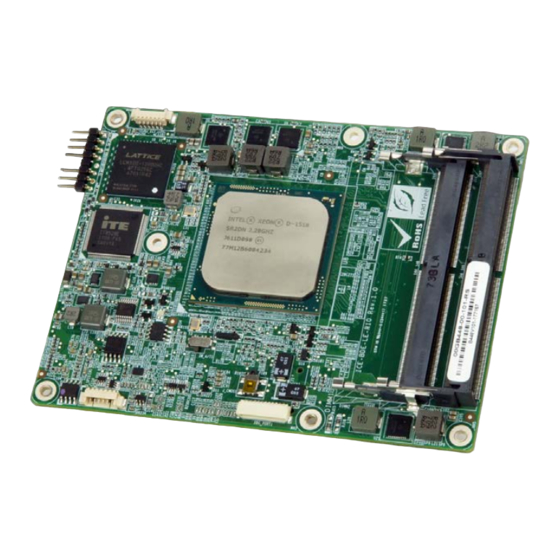
ICE-BDE-T7 COM Express Module Chapter Introduction Page 1... -
Page 12: Introduction
COM Express baseboard to be designed, while leaving the choice of processor till the later stages of design. The ICE-BDE-T7 provides a low power option with the full range of modern I/O options. The ICE-BDE-T7 embedded module is designed for flexible integration by system developers into customized platform devices. -
Page 13: Model Variations
ICE-BDE-T7 COM Express Module 1.2 Model Variations The model variations for the ICE-BDE-T7 series are listed in Table 1-1. On-board SoC Model Name Clock Speed # of Cores L2 Cache Max TDP ICE-BDE-T7-1548 Intel® Xeon® D-1548 2.0 GHz 12 MB... -
Page 14: Board Overview
ICE-BDE-T7 COM Express Module 1.4 Board Overview The on-board components and connectors of the ICE-BDE-T7 are shown in the figures below. Figure 1-2: On-board Components and Connectors Page 4... -
Page 15: Dimensions
ICE-BDE-T7 COM Express Module 1.5 Dimensions The main dimensions of the ICE-BDE-T7 are shown in the diagrams below. Figure 1-3: ICE-BDE-T7 Dimensions (without heatsink) (mm) Figure 1-4: ICE-BDE-T7 Dimensions (with heatsink) (mm) Page 5... -
Page 16: Data Flow
ICE-BDE-T7 COM Express Module 1.6 Data Flow Figure 1-5 shows the data flow between the system chipset, the CPU and other components installed on the motherboard. Figure 1-5: Data Flow Diagram Page 6... -
Page 17: Technical Specifications
ICE-BDE-T7 COM Express Module 1.7 Technical Specifications The ICE-BDE-T7 technical specifications are listed below. ICE-BDE-T7 PICMG COM Express R3.0 Type 7 Form Factor Intel® Xeon® processor D-1548 (12 MB Cache, 2.00 GHz) Intel® Xeon® processor D-1518 (6 MB Cache, 2.20 GHz) Processor Intel®... -
Page 18: Table 1-2: Ice-Bde-T7 Specifications
ICE-BDE-T7 COM Express Module ICE-BDE-T7 Operating -20ºC ~ 60ºC, with 0.7m/s air flow Temperature Storage Temperature -30ºC ~ 70ºC Operating Humidity 5% ~ 95% (non-condensing) Dimensions 125 mm x 95 mm Weight (GW/NW) 600 g / 300 g Table 1-2: ICE-BDE-T7 Specifications... -
Page 19: Packing List
ICE-BDE-T7 COM Express Module Chapter Packing List Page 9... -
Page 20: Anti-Static Precautions
Only handle the edges of the PCB: Don't touch the surface of the motherboard. Hold the motherboard by the edges when handling. 2.2 Unpacking Precautions When the ICE-BDE-T7 is unpacked, please do the following: Follow the antistatic guidelines above. -
Page 21: Packing List
Contact the IEI reseller or vendor the ICE-BDE-T7 purchased from contact sales representative directly by sending an email to sales@ieiworld.com. The ICE-BDE-T7 is shipped with the following components: Quantity Item and Part Number Image ICE-BDE-T7 COM Express Module Heatsink Utility CD... -
Page 22: Optional Items
ICE-BDE-T7 COM Express Module 2.4 Optional Items The following are optional components which may be separately purchased: Item and Part Number Image Baseboard for COM Express Type 7 modules (P/N: ICE-DB-T7-i2-R10) Table 2-2: Optional Items Page 12... -
Page 23: Connectors
ICE-BDE-T7 COM Express Module Chapter Connectors Page 13... -
Page 24: Peripheral Interface Connectors
ICE-BDE-T7 COM Express Module 3.1 Peripheral Interface Connectors This chapter details all the connectors. 3.1.1 ICE-BDE-T7 Layout The figures below show all the connectors on the front side and the solder side. Figure 3-1: Connectors (Front Side) Figure 3-2: Connectors (Solder Side) -
Page 25: Peripheral Interface Connectors
ICE-BDE-T7 COM Express Module 3.1.2 Peripheral Interface Connectors The table below lists all the connectors on the ICE-BDE-T7. Connector Type Label COM Express A-B connector COM Express connector COM Express C-D connector COM Express connector Clear CMOS button Push button... -
Page 26: Figure 3-3: Com Express A-B Connector Location
ICE-BDE-T7 COM Express Module Figure 3-3: COM Express A-B Connector Location Pin No. Description Pin No. Description GBE0_MDI3- GBE0_ACT# GBE0_MDI3+ LPC_FRAME# GBE0_LINK100# LPC_AD0 GBE0_LINK1000# LPC_AD1 GBE0_MDI2- LPC_AD2 GBE0_MDI2+ LPC_AD3 LPC_DRQ#0 GBE0_MDI1- GBE0_MDI1+ LPC_CLK GBE0_MDI0- PWRBTN# GBE0_MDI0+ SMB_CK SMB_DATA PM_SLP_S3# SMB_ALERT#... - Page 27 ICE-BDE-T7 COM Express Module Pin No. Description Pin No. Description PE2_TX_DP_6 PE2_RX_DP_6 PE2_TX_DN_#6 PE2_RX_DN_#6 WDTRST# SATA_LED# SPKR I2C_CLK BIOS_DISABLE# I2C_DAT PE2_TX_DP_5 PE2_RX_DP_5 PE2_TX_DN_#5 PE2_RX_DN_#5 PE2_TX_DP_4 PE2_RX_DP_4 PE2_TX_DN_#4 PE2_RX_DN_#4 USB2- USB3- USB2+ USB3+ USB_2_3_OC# USB_0_1_OC# USB0- USB1- USB0+ USB1+ +V3.3A_RTC SYS_RESET#...
- Page 28 ICE-BDE-T7 COM Express Module Pin No. Description Pin No. Description DOUT2 PCIE_TX_DP_4 PCIE_RX_DP_4 PCIE_TX_DN#_4 PCIE_RX_DN#_4 PCIE_TX_DP_3 PCIE_RX_DP_3 PCIE_TX_DN#_3 PCIE_RX_DN#_3 DIN1 DOUT3 PCIE_TX_DP_2 PCIE_RX_DP_2 PCIE_TX_DN#_2 PCIE_RX_DN#_2 WAKE0# DIN2 PCIE_TX_DP_1 PCIE_RX_DP_1 PCIE_TX_DN#_1 PCIE_RX_DN#_1 PE2_TX_DP_0 PE2_RX_DP_0 PE2_TX_DN_#0 PE2_RX_DN_#0 PE2_TX_DP_1 PE2_RX_DP_1 PE2_TX_DN_#1 PE2_RX_DN_#1 PE2_TX_DP_2...
-
Page 29: Com Express C-D Connector
ICE-BDE-T7 COM Express Module Pin No. Description Pin No. Description CLK_PCIE_CLK_N NCSI_CLK SPI_MISO NCSI_RXD1 DOUT0 NCSI_RXD0 SPI_CLK NCSI_CRS SPI_MOSI NCSI_TXD1 NCSI_TXD0 SPI_CS RS1_TX RS1_RX A100 B100 RS2_TX FAN_PWMOUT A101 B101 RS2_RX FAN_TACHIN A102 B102 LID# SLEEP# A103 B103 VCC_12V VCC_12V... -
Page 30: Figure 3-4: Com Express C-D Connector Location
ICE-BDE-T7 COM Express Module Figure 3-4: COM Express C-D Connector Location Pin No. Description Pin No. Description USB3_RXN_0 USB3_TXN_0 USB3_RXP_0 USB3_TXP_0 USB3_RXN_1 USB3_TXN_1 USB3_RXP_1 USB3_TXP_1 USB3_RXN_2 USB3_TXN_2 USB3_RXP_2 USB3_TXP_2 USB3_RXN_3 USB3_TXN_3 USB3_RXP_3 USB3_TXP_3 PCIE_RX_DP_7 PCIE_TX_DP_7 PCIE_RX_DP#_7 PCIE_TX_DP#_7 PCIE_RX_DP_8 PCIE_TX_DP_8 PCIE_RX_DP#_8... - Page 31 ICE-BDE-T7 COM Express Module Pin No. Description Pin No. Description LAN_FLSH_DI* LAN_FLSH_CS_N* LAN_I2C_SDA* 10G_SFP+_Present_N* LAN_I2C_SCL* 10G_Baset_Present_N* LAN_MDC1_LED1_1* LAN_FLSH_CLK* LAN_MDIO1_LED1_0* LAN_FLSH_DO* LAN_SDP0_1* LAN_SDP0_0* GBE_KR_RX1_P GBE_KR_TX1_P GBE_KR_RX1_N GBE_KR_TX1_N LAN_MDC0_LED0_1* LAN_MDIO_DIR_CTL1 LAN_MDIO0_ LED0_0* LAN_MDIO_DIR_CTL0 LAN_SDP1_1 LAN_SDP1_0 GBE_KR_RX0_P GBE_KR_TX0_P GBE_KR_RX0_N GBE_KR_TX0_N PE1_RX_DP_0 PE1_TX_DP_0 PE1_RX_DN#_0...
- Page 32 ICE-BDE-T7 COM Express Module Pin No. Description Pin No. Description PE1_RX_DP_2 PE1_TX_DP_2 PE1_RX_DN#_2 PE1_TX_DN#_2 GND21 PE1_RX_DP_3 PE1_TX_DP_3 PE1_RX_DN#_3 PE1_TX_DN#_3 PE1_RX_DP_4 PE1_TX_DP_4 PE1_RX_DN#_4 PE1_TX_DN#_4 PE1_RX_DP_5 PE1_TX_DP_5 PE1_RX_DN#_5 PE1_TX_DN#_5 PE1_RX_DP_6 PE1_TX_DP_6 PE1_RX_DN#_6 PE1_TX_DN#_6 PE1_RX_DP_7 PE1_TX_DP_7 PE1_RX_DN#_7 PE1_TX_DN#_7 PE1_RX_DP_8 PE1_TX_DP_8 PE1_RX_DN#_8 PE1_TX_DN#_8 PE1_RX_DP_9...
-
Page 33: Table 3-3: Com Express C-D Connector Pin Definitions
ICE-BDE-T7 COM Express Module Pin No. Description Pin No. Description PE1_RX_DP_12 PE1_TX_DP_12 PE1_RX_DN#_12 PE1_TX_DN#_12 PE1_RX_DP_13 PE1_TX_DP_13 PE1_RX_DN#_13 PE1_TX_DN#_13 PE1_RX_DP_14 PE1_TX_DP_14 PE1_RX_DN#_14 PE1_TX_DN#_14 C100 D100 PE1_RX_DP_15 PE1_TX_DP_15 C101 D101 PE1_RX_DN#_15 PE1_TX_DN#_15 C102 D102 C103 D103 VCC_12V VCC_12V C104 D104 VCC_12V VCC_12V... -
Page 34: Cpld Programming Connector
ICE-BDE-T7 COM Express Module 3.2.1 CPLD Programming Connector CN Label: J_CPLD1 CN Type: 8-pin header, p=2.54 mm CN Location: See Figure 3-5 See Table 3-4 CN Pinouts: The CPLD programming connector location and pinouts are shown below. Figure 3-5: CPLD Programming Connector Location Pin No. -
Page 35: Ddr4 So-Dimm Connectors
ICE-BDE-T7 COM Express Module 3.2.2 DDR4 SO-DIMM Connectors CN Label: DIMM1, DIMM2 260-pin DDR4 SO-DIMM connector CN Type: CN Location: See Figure 3-6 The SO-DIMM connectors are for installing DDR4 memory on the system. NOTE: For dual channel configuration, always install two identical memory modules that feature the same capacity, timings, voltage, number of ranks and the same brand. -
Page 36: Debug Port, Lpc
ICE-BDE-T7 COM Express Module 3.2.1 Debug Port, LPC CN Label: DBG_PORT1 CN Type: 12-pin wafer, p=1.00 mm CN Location: See Figure 3-7 See Table 3-5 CN Pinouts: The LPC debug port location and pinouts are shown below. Figure 3-7: LPC Debug Port Location Pin No. -
Page 37: Debug Port, Ec
ICE-BDE-T7 COM Express Module 3.2.1 Debug Port, EC CN Label: DBG_EC1 CN Type: 20-pin FPC, p=0.5 mm CN Location: See Figure 3-8 See Table 3-6 CN Pinouts: The EC debug port location and pinouts are shown below. Figure 3-8: EC Debug Port Location Pin No. -
Page 38: Spi Flash Connector, Bios
ICE-BDE-T7 COM Express Module 3.2.1 SPI Flash Connector, BIOS CN Label: J_SPI1 CN Type: 6-pin wafer, p=1.25 mm CN Location: See Figure 3-9 See Table 3-7 CN Pinouts: The BIOS SPI flash connector location and pinouts are shown below. Figure 3-9: BIOS SPI Flash Connector Location Pin No. -
Page 39: Spi Flash Connector, Ec
ICE-BDE-T7 COM Express Module 3.2.1 SPI Flash Connector, EC CN Label: J_EC1 CN Type: 6-pin wafer, p=1.25 mm CN Location: See Figure 3-10 See Table 3-8 CN Pinouts: The EC SPI flash connector location and pinouts are shown below. Figure 3-10: EC SPI Flash Connector Location Pin No. -
Page 40: Installation
ICE-BDE-T7 COM Express Module Chapter Installation Page 30... -
Page 41: Anti - Static Precautions
Electrostatic discharge (ESD) can cause serious damage to electronic components, including the ICE-BDE-T7. Dry climates are especially susceptible to ESD. It is therefore critical that whenever the ICE-BDE-T7 or any other electrical component is handled, the following anti-static precautions are strictly adhered to. - Page 42 Turn all power to the ICE-BDE-T7 off: When working with the ICE-BDE-T7, make sure that it is disconnected from all power supplies and that no electricity is being fed into the system. Before and during the installation of the ICE-BDE-T7 DO NOT: ...
-
Page 43: So-Dimm Installation
Figure 4-1. Figure 4-1: SO-DIMM Installation Step 1: Locate the SO-DIMM socket. Place the ICE-BDE-T7 on an anti-static mat with the front side facing up. Step 2: Align the SO-DIMM with the socket. Align the notch on the memory with the notch on the memory socket. -
Page 44: Mounting Ice-Bde-T7 To Baseboard
Follow the steps below to install the ICE-BDE-T7 to the optional baseboard. Step 1: Align the two COM Express connector on the solder side of the ICE-BDE-T7 with the corresponding connector on the baseboard. Gently push the COM Express module down to ensure the connectors are properly connected (Figure 4-2). -
Page 45: Figure 4-2: Connect The Com Express Connectors
ICE-BDE-T7 COM Express Module Figure 4-2: Connect the COM Express Connectors Step 2: Ensure a thermal pad is placed on the CPU of the ICE-BDE-T7. Step 3: Place the heatsink on the ICE-BDE-T7, aligning the retention screw holes (Figure 4-3). -
Page 46: Bios
ICE-BDE-T7 COM Express Module Chapter BIOS Page 36... -
Page 47: Introduction
ICE-BDE-T7 COM Express Module 5.1 Introduction The BIOS is programmed onto the BIOS chip. The BIOS setup program allows changes to certain system settings. This chapter outlines the options that can be changed. NOTE: Some of the BIOS options may vary throughout the life cycle of the product and are subject to change without prior notice. -
Page 48: Getting Help
ICE-BDE-T7 COM Express Module Function Decrease the numeric value or make changes F1 key General help, only for Status Page Setup Menu and Option Page Setup Menu F2 key Load previous values. F3 key Load optimized defaults F4 key Save changes and Exit BIOS Esc key Main Menu –... -
Page 49: Main
ICE-BDE-T7 COM Express Module 5.2 Main The Main BIOS menu (BIOS Menu 1) appears when the BIOS Setup program is entered. Aptio Setup Utility – Copyright (C) 2017 American Megatrends, Inc. Main Advanced IntelRCSetup Server Mgmt Security Boot Event Logs Save & Exit... -
Page 50: Bios Menu 2: Advanced
ICE-BDE-T7 COM Express Module WARNING! Setting the wrong values in the sections below may cause the system to malfunction. Make sure that the settings made are compatible with the hardware. Aptio Setup Utility – Copyright (C) 2017 American Megatrends, Inc. -
Page 51: Trusted Computing
ICE-BDE-T7 COM Express Module 5.3.1 Trusted Computing Use the Trusted Computing menu (BIOS Menu 3) to configure settings related to the Trusted Computing Group (TCG) Trusted Platform Module (TPM). Aptio Setup Utility – Copyright (C) 2017 American Megatrends, Inc. Main... -
Page 52: Iwdd H/W Monitor
ICE-BDE-T7 COM Express Module 5.3.2 iWDD H/W Monitor The iWDD H/W Monitor menu (BIOS Menu 4) contains the fan configuration submenus and displays operating temperature, fan speeds and system voltages. Aptio Setup Utility – Copyright (C) 2017 American Megatrends, Inc. -
Page 53: Smart Fan Mode Configuration
ICE-BDE-T7 COM Express Module +3.3VSB 5.3.2.1 Smart Fan Mode Configuration Use the Smart Fan Mode Configuration submenu (BIOS Menu 5) to configure fan temperature and speed settings. Aptio Setup Utility – Copyright (C) 2017 American Megatrends, Inc. Advanced Smart Fan Mode Configuration... - Page 54 ICE-BDE-T7 COM Express Module Auto mode fan start temperature [40] WARNING: Setting this value too high may cause the fan to rotate at full speed only when the CPU is at a very high temperature and therefore cause the system to be damaged.
-
Page 55: Iwdd Super Io Configuration
ICE-BDE-T7 COM Express Module Auto mode fan slope PWM [2] The Auto mode fan slope PWM option can only be set if the CPU_FAN1 Smart Fan control option is set to Auto Mode. Use the Auto mode fan slope PWM option to select the linear rate at which the PWM mode increases with respect to an increase in temperature. -
Page 56: Serial Port N Configuration
ICE-BDE-T7 COM Express Module 5.3.3.1 Serial Port n Configuration Use the Serial Port n Configuration menu (BIOS Menu 7) to configure the serial port n. Aptio Setup Utility – Copyright (C) 2017 American Megatrends, Inc. Advanced Serial Port 1 Configuration... - Page 57 ICE-BDE-T7 COM Express Module IO=3F8h; IRQ=3, Serial Port I/O port address is 3F8h and the 4,5,6,7,9,10,11,12 interrupt address is IRQ3,4,5,6,7,9,10,11,12 Serial Port I/O port address is 2F8h and the IO=2F8h; IRQ=3, interrupt address is IRQ3,4,5,6,7,9,10,11,12 4,5,6,7,9,10,11,12 IO=3E8h; IRQ=3,...
-
Page 58: Rtc Wake Settings
ICE-BDE-T7 COM Express Module IO=2E8h; IRQ=3, Serial Port I/O port address is 2E8h and the 4,5,6,7,9,10,11,12 interrupt address is IRQ3,4,5,6,7,9,10,11,12 5.3.4 RTC Wake Settings The RTC Wake Settings menu (BIOS Menu 8) configures RTC wake event. Aptio Setup Utility – Copyright (C) 2017 American Megatrends, Inc. -
Page 59: Serial Port Console Redirection
ICE-BDE-T7 COM Express Module Wake up date Wake up hour Wake up minute Wake up second After setting the alarm, the computer turns itself on from a suspend state when the alarm goes off. 5.3.5 Serial Port Console Redirection The Serial Port Console Redirection menu (BIOS Menu 9) allows the console redirection options to be configured. -
Page 60: Legacy Console Redirection Settings
ICE-BDE-T7 COM Express Module Console Redirection [Disabled] Use Console Redirection option to enable or disable the console redirection function. Disabled the console redirection function Disabled EFAULT Enabled the console redirection function Enabled 5.3.5.1 Legacy Console Redirection Settings The Legacy Console Redirection Settings menu (BIOS Menu 10) allows the legacy console redirection options to be configured. -
Page 61: Console Redirection Settings
ICE-BDE-T7 COM Express Module 5.3.5.2 Console Redirection Settings The Console Redirection Settings menu (BIOS Menu 11) allows the console redirection options to be configured. The option is active when Console Redirection option is enabled. Aptio Setup Utility – Copyright (C) 2016 American Megatrends, Inc. - Page 62 ICE-BDE-T7 COM Express Module Bits per second [115200] Use the Bits per second option to specify the serial port transmission speed. The speed must match the other side. Long or noisy lines may require lower speeds. 9600 Sets the serial port transmission speed at 9600.
-
Page 63: Usb Configuration
ICE-BDE-T7 COM Express Module Stop Bits [1] Use the Stop Bits option to specify the number of stop bits used to indicate the end of a serial data packet. Communication with slow devices may require more than 1 stop bit. -
Page 64: Iei Feature
ICE-BDE-T7 COM Express Module Legacy USB Support [Enabled] Use the Legacy USB Support BIOS option to enable USB mouse and USB keyboard support. Normally if this option is not enabled, any attached USB mouse or USB keyboard does not become available until a USB compatible operating system is fully booted with all USB drivers loaded. -
Page 65: Intelrcsetup
ICE-BDE-T7 COM Express Module Auto Recovery Function [Disabled] Use the Auto Recovery Function BIOS option to enable or disable the auto recovery function of the IEI One Key Recovery. Disabled Auto recovery function disabled EFAULT Auto recovery function enabled Enabled 5.4 IntelRCSetup... -
Page 66: Processor Configuration
ICE-BDE-T7 COM Express Module 5.4.1 Processor Configuration Use the Processor Configuration menu (BIOS Menu 15) to view detailed CPU specifications and configure the CPU. Aptio Setup Utility – Copyright (C) 2017 American Megatrends, Inc. IntelRCSetup CPU Configuration Enable Hyper Threading... - Page 67 ICE-BDE-T7 COM Express Module Intel TXT [Disable] ® Use the Intel TXT BIOS option to enable or disable Intel Trusted Execution Technology. ® Disables the use of Intel Trusted Execution Disable EFAULT technology ® Enables the use of Intel...
-
Page 68: Iio Configuration
ICE-BDE-T7 COM Express Module 5.4.2 IIO Configuration Use the IIO Configuration menu (BIOS Menu 16) to configure the IIO parameters. Aptio Setup Utility – Copyright (C) 2017 American Megatrends, Inc. IntelRCsetup IIO Configuration ------------------------------------------ > IIO Configuration > Intel VT for Directed I/O (VT-d) >... -
Page 69: Intel Vt For Directed I/O (Vt-D)
ICE-BDE-T7 COM Express Module The PCIe slot submenus all contain the following options: Link Speed [Auto] Use the Link Speed option to configure the PCIe interface speed. Auto EFAULT Gen 1 (2.5 GT/s) Gen 2 (5 GT/s) ... -
Page 70: Iio South Complex Configuration
ICE-BDE-T7 COM Express Module VT-d Intel VT for Directed I/O (VT-d) [Disable] Use the Intel VT for Directed I/O (VT-d) option to enable or disable VT-d support. Disable VT-d support. Disable EFAULT Enable VT-d support. Enable 5.4.2.3 IIO South Complex Configuration Use the IIO South Complex submenu (BIOS Menu 19) to configure South Complex settings. -
Page 71: Pch Configuration
ICE-BDE-T7 COM Express Module 5.4.3 PCH Configuration Use the PCH Configuration menu (BIOS Menu 20) to configure the PCH chipset. Aptio Setup Utility – Copyright (C) 2017 American Megatrends, Inc. IntelRCSetup PCH Configuration PCI Express Configuration --------------------------------------------- settings > PCI Express Configuration >... -
Page 72: Pch Sata Configuration
ICE-BDE-T7 COM Express Module The PCIe slot submenus all contain the following options: PCIe Speed [Auto] Use the PCIe Speed option to configure the PCIe interface speed. Auto EFAULT Gen 1 Gen 2 5.4.3.2 PCH SATA Configuration Use the PCH SATA Configuration menu (BIOS Menu 22) to change and/or set the configuration of the SATA devices installed in the system. - Page 73 ICE-BDE-T7 COM Express Module Configure SATA as [AHCI] Use the Configure SATA as option to configure SATA devices as IDE, AHCI or RAID devices. Configures SATA devices as IDE device. Configures SATA devices as AHCI device. AHCI EFAULT ...
-
Page 74: Server Management
ICE-BDE-T7 COM Express Module 5.5 Server Management Use the Server Management menu (BIOS Menu 23) to display the server management status and change the settings. Aptio Setup Utility – Copyright (C) 2017 American Megatrends, Inc. Main Advanced IntelRCSetup Server Mgmt... -
Page 75: Bios Menu 24: System Event Log
ICE-BDE-T7 COM Express Module Aptio Setup Utility – Copyright (C) 2017 American Megatrends, Inc. Server Mgmt Enabling/Disabling Options Change this to enable or SEL Components [Enabled] disable all features of System Event Logging Erase Settings during boot. Erase SEL [No]... -
Page 76: Bios Menu 25: Security
ICE-BDE-T7 COM Express Module When SEL is full [Do Nothing] Use the When SEL is Full option to determine the action to be taken when SEL is full. The following options are available: Do Nothing Default Erase Immediately 5.6 Security... -
Page 77: Bios Menu 26: Boot
ICE-BDE-T7 COM Express Module 5.7 Boot Use the Boot menu (BIOS Menu 26) to configure system boot options. Aptio Setup Utility – Copyright (C) 2017 American Megatrends, Inc. Main Advanced IntelRCSetup Server Mgmt Security Boot Event Logs Save & Exit... - Page 78 ICE-BDE-T7 COM Express Module Does not enable the keyboard Number Lock automatically. To use the 10-keys on the keyboard, press the Number Lock key located on the upper left-hand corner of the 10-key pad. The Number Lock LED on the keyboard lights up when the Number Lock is engaged.
-
Page 79: Bios Menu 27: Save & Exit
ICE-BDE-T7 COM Express Module Keep Sets display mode to current. Current Boot Option Priority Use the Boot Option Priority function to set the system boot sequence from the available devices. The drive sequence also depends on the boot sequence in the individual device section. - Page 80 ICE-BDE-T7 COM Express Module Discard Changes and Reset Use the Discard Changes and Reset option to exit the system without saving the changes made to the BIOS configuration setup program. Restore Defaults Use the Restore Defaults option to load the optimal default values for each of the parameters on the Setup menus.
-
Page 81: Software Drivers
ICE-BDE-T7 COM Express Module Chapter Software Drivers Page 71... -
Page 82: S Oftware I Nstallation
Visit the IEI website or contact technical support for the latest updates. 6.1 Software Installation All the drivers for the ICE-BDE-T7 are on the CD that came with the system. To install the drivers, please follow the steps below. Step 1: Insert the CD that came with the system into a CD drive connected to the system. -
Page 83: A Regulatory Compliance
ICE-BDE-T7 COM Express Module Appendix Regulatory Compliance Page 73... - Page 84 ICE-BDE-T7 COM Express Module DECLARATION OF CONFORMITY This equipment has been tested and found to comply with specifications for CE marking. If the user modifies and/or installs other devices in the equipment, the CE conformity declaration may no longer apply.
-
Page 85: B Product Disposal
ICE-BDE-T7 COM Express Module Appendix Product Disposal Page 75... - Page 86 ICE-BDE-T7 COM Express Module CAUTION: Risk of explosion if battery is replaced by an incorrect type. Only certified engineers should replace the on-board battery. Dispose of used batteries according to instructions and local regulations. Outside the European Union–If you wish to dispose of used electrical and electronic products outside the European Union, please contact your local authority so as to comply with the correct disposal method.
-
Page 87: C Bios Options
ICE-BDE-T7 COM Express Module Appendix BIOS Options Page 77... - Page 88 ICE-BDE-T7 COM Express Module Below is a list of BIOS configuration options in the BIOS chapter. System Date [xx/xx/xx] ......................39 System Time [xx:xx:xx] ....................... 39 Restore AC Power Loss [Last State] ................. 40 Security Device Support [Disable] ..................41 PC Health Status ........................
- Page 89 ICE-BDE-T7 COM Express Module PCIe Speed [Auto] ........................ 62 STAT Controller [Enabled] ....................62 Configure SATA as [AHCI] ....................63 Hot Plug [Disabled] ......................63 SEL Components [Enabled] ....................65 Erase SEL [No] ........................65 When SEL is full [Do Nothing] .................... 66 Administrator Password .....................
-
Page 90: D Digital I/O Interface
ICE-BDE-T7 COM Express Module Appendix Digital I/O Interface Page 80... - Page 91 ICE-BDE-T7 COM Express Module The DIO connector on the ICE-BDE-T7 is interfaced to GPIO ports on the Super I/O chipset. The DIO has both 8-bit digital inputs and 8-bit digital outputs. The digital inputs and digital outputs are generally control signals that control the on/off circuit of external devices or TTL devices.
- Page 92 ICE-BDE-T7 COM Express Module AH – 6FH Sub-function: AL – 9 :Set the digital port as OUTPUT :Digital I/O output value Assembly Language Sample 2 AX, 6F09H ;setting the digital port as output BL, 09H ;digital value is 09H Digital Output is 1001b...
-
Page 93: E Watchdog Timer
ICE-BDE-T7 COM Express Module Appendix Watchdog Timer Page 83... - Page 94 ICE-BDE-T7 COM Express Module NOTE: The following discussion applies to DOS environment. Contact IEI support or visit the IEI website for specific drivers for other operating systems. The Watchdog Timer is provided to ensure that standalone systems can always recover from catastrophic conditions that cause the CPU to crash.
- Page 95 ICE-BDE-T7 COM Express Module NOTE: When exiting a program it is necessary to disable the Watchdog Timer, otherwise the system resets. EXAMPLE PROGRAM: ; INITIAL TIMER PERIOD COUNTER W_LOOP: AX, 6F02H ;setting the time-out value BL, 30 ;time-out value is 48 seconds ;...
-
Page 96: F Hazardous Materials Disclosure
ICE-BDE-T7 COM Express Module Appendix Hazardous Materials Disclosure Page 86... - Page 97 ICE-BDE-T7 COM Express Module The details provided in this appendix are to ensure that the product is compliant with the People’s Republic of China (China) RoHS standards. The table below acknowledges the presences of small quantities of certain materials in the product, and is applicable to China RoHS only.
- Page 98 ICE-BDE-T7 COM Express Module 此附件旨在确保本产品符合中国 RoHS 标准。以下表格标示此产品中某有毒物质的含量符 合中国 RoHS 标准规定的限量要求。 本产品上会附有”环境友好使用期限”的标签,此期限是估算这些物质”不会有泄漏或突变”的 年限。本产品可能包含有较短的环境友好使用期限的可替换元件,像是电池或灯管,这些元 件将会单独标示出来。 部件名称 有毒有害物质或元素 铅 汞 镉 六价铬 多溴联苯 多溴二苯 醚 (Pb) (Hg) (Cd) (CR(VI)) (PBB) (PBDE) 壳体 显示 印刷电路板 金属螺帽 电缆组装 风扇组装 电力供应组装 电池 O: 表示该有毒有害物质在该部件所有物质材料中的含量均在 SJ/T 11363-2006 (现由 GB/T 26572-2011 取代) 标准规定的限量要求以下。...
Need help?
Do you have a question about the ICE-BDE-T7 and is the answer not in the manual?
Questions and answers