Table of Contents
Advertisement
Quick Links
Advertisement
Table of Contents

Related Manuals for AXIOMTEK IPC912 Series


Summary of Contents for AXIOMTEK IPC912 Series
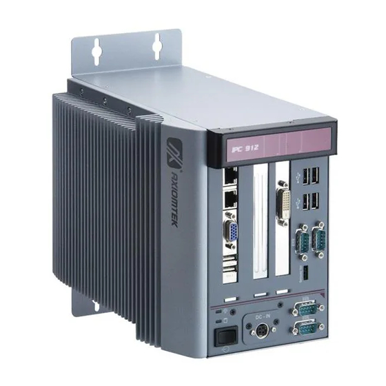
- Page 1 IPC912 Series Industrial & Fanless Computers User’s Manual...
- Page 2 Axiomtek does not make any commitment to update the information in this manual. Axiomtek reserves the right to change or revise this document and/or product at any time without notice. No part of this document may be reproduced, stored in a retrieval...
-
Page 3: Safety Precautions
Safety Precautions Before getting started, please read the following important safety precautions. The IPC912 Series does not come equipped with an operating system. An operating system must be loaded first before installing any software into the computer. Be sure to ground yourself to prevent static charge when installing the internal components. -
Page 4: Classification
IPC912 Series User’s Manual Classification Degree of production against electric shock: not classified Degree of protection against the ingress of water: IPX0 Equipment not suitable for use in the presence of a flammable anesthetic mixture with air or with oxygen or nitrous oxide. - Page 5 IPC912 Series User’s Manual Cloth: A piece of cloth is the best tool to use when rubbing up a component. Although paper towels or tissues can be used on most hardware as well, we still recommend you to rub it with a piece of cloth.
-
Page 6: Scrap Computer Recycling
If the computer equipments need the maintenance or are beyond repair, we strongly recommended that you should inform your Axiomtek distributor as soon as possible for the suitable solution. For the computers that are no longer useful or no longer working well, please contact your Axiomtek distributor for recycling and we will make the proper arrangement. -
Page 7: Table Of Contents
IPC912 Series User’s Manual Table of Contents Disclaimers................ ii Safety Precautions ............iii Classification ..............iv General Cleaning Tips............. iv Scrap Computer Recycling..........vi CHAPTER 1................1 INTRODUCTION ..............1 General Description.......... 2 System Specifications........3 1.2.1 Main CPU Board............3 1.2.2... - Page 8 IPC912 Series User’s Manual Boot Menu ............45 Security Menu ..........48 EXIT Menu ............54 Appendix A ................56 CAN BUS Module Introduce..........56 viii...
- Page 9 IPC912 Series User’s Manual MEMO...
-
Page 11: Chapter 1
IPC912 Series User’s Manual CHAPTER 1 INTRODUCTION This chapter contains general information and a detailed specification of the IPC912 Series. Chapter 1 includes the following sections: General Description System Specification Dimensions I/O Outlets Package List Introduction... -
Page 12: General Description
IPC912 Series User’s Manual General Description The IPC912 Series is a fanless system that can support Socket P for ® ® Intel Core 2 Duo/Celeron M processors. The IPC912 Series ® ® supports Windows XP, and Windows XP embedded, Vista, and Fedora, suitable for the most endurable operation. -
Page 13: System Specifications
IPC912 Series User’s Manual System Specifications 1.2.1 Main CPU Board ® ® Socket P Intel Core 2 Duo/Celeron M processors System Chipset ® Intel GM45+ICH9M chipset BIOS AMI BIOS, with Smart View and Customer CMOS Backup. System Memory Two 204-pin DDR3 800/1066 MHz SODIMM sockets, with... -
Page 14: System Specification
IPC912 Series User’s Manual Expansion Slot HAB100: One PCIex1 & 1 PCIex4 or 2 PCIex1 HAB103: One PCI & One PCIex4 HAB102: One PCIex4 & One PCI-X NOTE The maximum power rating for expansion slots at 45℃can not be exceeded the following values +5V+5Vsb+3.3V<34W... -
Page 15: Dimensions
IPC912 Series User’s Manual Dimensions The following diagrams show you dimensions and outlines of the IPC912 Series. Introduction... -
Page 16: I/O Outlets
IPC912 Series User’s Manual I/O Outlets The following figures show you I/O outlets on front and rear panels of the IPC912 Series. Front Panel Ethernet x 2 VGA Port USB 2.0 x 2 LED for Power & HDD ATX Power Switch... -
Page 17: Jumper Settings
IPC912 Series User’s Manual Jumper Settings The IPC912 has a number of jumpers inside the chassis that allow you to configure your system to suit your application. The table below lists the functions of the various jumpers. These jumpers select the COM1 port’s communication mode to operate RS-232 or RS-422/485. - Page 18 IPC912 Series User’s Manual These jumpers select the COM1, COM2 ports’ DCD and RI mode. Description Function Jumper Setting COM1 DCD & RI Pin 1=12V Voltage Selection (JP6) Pin 1=5V *Pin 1=DCD (Default) Pin 8=12V Pin 8=5V *Pin 8=RI (Default)
- Page 19 IPC912 Series User’s Manual Description Function Jumper Setting COM2 DCD & RI Pin 1=12V Voltage Selection (JP5) Pin 1=5V *Pin 1=DCD (Default) Pin 8=12V Pin 8=5V *Pin 8=RI (Default) NOTE: If you are using COM2 as a CAN Bus module, please refer to Appedix A.
- Page 20 IPC912 Series User’s Manual CompactFlash™ Device Setting Jumper (JP8~11) Jumper Description Jumper Setting Description Jumper Setting CF Device Enable Disable (Default) ComplactFlash™ Voltage Selection Jumper (JP12) This jumper is to select the voltage for CompactFlash interface. Description Function Jumper Setting CompactFlash 3.3V (Default)
- Page 21 IPC912 Series User’s Manual USB Voltage Selection Jumpers (JP14, JP15, JP17) This jumper is to select the voltage for USB interface. Description Function Jumper Setting USB Voltage Selection 5V_SBY LVDS Voltage Selection Jumper (JP18) This jumper is to select the voltage for LVDS interface.
-
Page 22: Packing List
IPC912 Series User’s Manual Packing List The package bundled with your IPC912 Series should contain the following items: IPC912 Series Unit x 1 19V 150W Adapter and US Power Cord (for IPC912 AC Version) Driver CD Quick Manual Wall Mount Bracket x 2... -
Page 23: Chapter 2
IPC912 Series User’s Manual CHAPTER 2 HARDWARE INSTALLATION The IPC912 Series are convenient for your various hardware configurations, such as CPU (Central Processing Unit), Memory Module, HDD (Hard Disk Drive) and PCIe card. The chapter 2 will show you how to install the hardware. It includes: Installing the Processor ®... - Page 24 IPC912 Series User’s Manual If the cooling solution prevents you from accessing the processor socket, you may need to remove it. Instructions on how to remove your cooling solution should be provided in the documentation that came with the system.
- Page 25 IPC912 Series User’s Manual Step 4 After opening the top and side covers, you can locate the CPU socket and heatsink as marked. Align pins of the CPU with pin holes of the socket. Be careful of the CPU’s orientation that you need to align the arrow mark on the CPU with the arrow key on the socket.
- Page 26 IPC912 Series User’s Manual Step 6 Close the top and side covers back to the chassis, and fasten all screws. Hardware Installation...
-
Page 27: Installing The Memory Module
IPC912 Series User’s Manual Installing the Memory Module Step 1 Turn off the system. Step 2 Disconnect the power connector. Step 3 Loosen screws to remove the side cover from the chassis. Step 4 Please follow steps below to install the upper memory module: 1. - Page 28 IPC912 Series User’s Manual 2. Install the memory module into the socket and push it firmly down until it is fully seated. The socket latches are clipped on to the edges of the SO-DIMM. Step 5 Put back the side cover to the chassis and fasten all screws.
-
Page 29: Installing The Hard Disk Drive
IPC912 Series User’s Manual Installing the Hard Disk Drive The IPC912 Series offers a convenient drive bay module for users to install HDD. The system offers users one 2.5” Hard Disk Drive for installation. Please follow the steps: Step 1 Turn off the system. - Page 30 IPC912 Series User’s Manual Step 5 Use assembly parts to fix HDD with the bracket. Step 6 Install and fix the HDD through the side, next, plug the power cable in HDD. Step 7 Close the top cover back to the chassis and fasten all screws.
-
Page 31: Installing The Pci Or Pcie Card
IPC912 Series User’s Manual Installing the PCI or PCIe Card Step 1 Turn off the system. Step 2 Disconnect the power connector. Step 3 Loosen screws to remove the top cover from the chassis. Removing the PCI or PCIe bracket by releasing the button as marked. - Page 32 IPC912 Series User’s Manual Step 5 Align the PCI or PCIe card with the slot, and press the card into the slot until it is firmly seated. Step 6 Close the top cover back to the chassis and fasten all screws.
-
Page 33: Chapter 3
IPC912 Series User’s Manual CHAPTER 3 AMI BIOS UTILITY This chapter provides users with detailed description how to set up basic system configuration through the AMIBIOS8 BIOS setup utility. Starting To enter the setup screens, follow the steps below: Turn on the computer and press the <Del> key immediately. -
Page 34: The Main Menu
IPC912 Series User’s Manual The Main Menu Once you enter the AMI BIOS CMOS Setup Utility, the Main Menu appears on the screen. In the Main Menu, there are several Setup functions and a couple of Exit options for your selection. Use arrow keys to select the Setup Page you intend to configure then press <Enter>... -
Page 35: Advanced Bios Features
IPC912 Series User’s Manual Advanced BIOS Features The Advanced menu allows users to set configuration of the CPU and other system devices. You can select any of the items in the left frame of the screen to go to the sub menus:... - Page 36 IPC912 Series User’s Manual CPU Configuration This screen shows the CPU Configuration, and you can change the value of the selected option this section allows you to configure and improve your system, to set up some system features according to your preference.
- Page 37 IPC912 Series User’s Manual CPU Feature Scroll to this item and press <Enter> to view the CPU Feature sub menu. MPS Revision Use this item to select MPS (Multi Processor Specification) Revision 1.1 or 1.4. The default setting is 1.4.
- Page 38 IPC912 Series User’s Manual Adjacent Cache Line Prefetch This item has a hardware adjacent cache line prefetch mechanism that automatically fetches extra cache line whenever the processor requests for a cache line. This reduces cache latency by making the next cache line immediately available if the processor requires it as well.
- Page 39 IPC912 Series User’s Manual IDE Configuration You can use this screen to select options for the IDE Configuration, and change the value of the selected option. A description of the selected item appears on the right side of the screen. For items marked with “...
- Page 40 IPC912 Series User’s Manual Floppy Configuration You can use this screen to select options for the Floppy Configuration, and change the value of the selected option. A description of the selected item appears on the right side of the screen. For items marked with “ ”, please press <Enter> for more options.
- Page 41 IPC912 Series User’s Manual SuperIO Configuration You can use this screen to select options for the SuperIO Configuration, and change the value of the selected option. A description of the selected item appears on the right side of the screen.
- Page 42 IPC912 Series User’s Manual Serial Port2 Mode This item specifies the mode used by the serial port 2. Parallel Port Address Select an operating mode for the onboard parallel (printer) port. Parallel Port IRQ Use this item to set up the IRQ for onboard parallel port.
- Page 43 IPC912 Series User’s Manual Hardware Health Configuration This screen shows the Hardware Health Configuration, and a description of the selected item appears on the right side of the screen H/W Health Function You can select this item Enabled for the Hardware Health Monitoring Device.
- Page 44 IPC912 Series User’s Manual ACPI Configuration You can use this screen to select options for the ACPI Configuration, and change the value of the selected option. A description of the selected item appears on the right side of the screen.
- Page 45 IPC912 Series User’s Manual Interface) options for your configuration. AMI BIOS Utility...
- Page 46 IPC912 Series User’s Manual AHCI Configuration You can use this screen to select options for the AHCI Configuration, and change the value of the selected option. A description of the selected item appears on the right side of the screen.
- Page 47 IPC912 Series User’s Manual APM Configuration You can use this screen to select options for the APM Configuration, and change the value of the selected option. A description of the selected item appears on the right side of the screen.
- Page 48 IPC912 Series User’s Manual Power Button Mode This option specifies how the externally mounted power button on the front of the computer chassis is used. The default setting is On/Off. Pushing the power button turns the computer on or On/Off off.
- Page 49 IPC912 Series User’s Manual This setting prevents hard disk drive power down Disabled mode. This option stops the hard disk drives from spinning Standby during a system standby. This option cuts the power to the hard disk drives Suspend during a system suspend. This is the default setting.
- Page 50 IPC912 Series User’s Manual Event Log Configuration This screen shows the Event Log Configuration, and a description of the selected item appears on the right side of the screen. View Event Log This item is to display the system events in the System Event Log.
- Page 51 IPC912 Series User’s Manual Smbios Configuration You can use this screen to select options for the Smbios Configuration, and change the value of the selected option. A description of the selected item appears on the right side of the screen.
- Page 52 IPC912 Series User’s Manual USB Configuration You can use this screen to select options for the USB Configuration, and change the value of the selected option. A description of the selected item appears on the right side of the screen.
-
Page 53: Pci Pnp Menu
IPC912 Series User’s Manual PCI PnP Menu The PCI PnP menu allows users to change the advanced settings for PCI/PnP devices. Clear NVRAM Use this item to clear the data in the NVRAM (CMOS). Here are the options for your selection, No and Yes. - Page 54 IPC912 Series User’s Manual Allocate IRQ to PCI VGA This item allows BIOS to choose an IRQ to assign for the PCI VGA card. Here are the options for your selection, No and Yes. Palette Snooping Some old graphic controllers need to “snoop” on the VGA palette, and then map it to their display as a way to provide boot information and VGA compatibility.
-
Page 55: Boot Menu
IPC912 Series User’s Manual Boot Menu The Boot menu allows users to change boot options of the system. You can select any of the items in the left frame of the screen to go to the sub menus: Boot Settings Configuration For items marked with “... - Page 56 IPC912 Series User’s Manual Boot Settings Configuration Quick Boot Enabling this item lets the BIOS skip some power on self tests (POST). The default setting is Enabled. LAN1/LAN2 Boot Use these items to enable or disable the Boot ROM function of the onboard LAN chip when the system boots AddOn ROM Display Mode This item selects the display mode for option ROM.
- Page 57 IPC912 Series User’s Manual Hit ‘DEL’ Message Display If this item is enabled, the system displays the message “Press DEL to run Setup” during POST.The default setting is Enabled. Interrupt 19 Capture If this item is enabled, this function makes the option ROMs to trap Interrupt 19.
-
Page 58: Security Menu
IPC912 Series User’s Manual Security Menu The Security menu allows users to change the security settings for the system. Supervisor Password This item indicates whether a supervisor password has been set. If the password has been installed, Installed displays. If not, Not Installed displays. - Page 59 IPC912 Series User’s Manual Change User Password Select this option and press <Enter> to access the sub menu. You can use the sub menu to change the user password. Boot Sector Virus Protection This option is near the bottom of the Security Setup screen.
- Page 60 IPC912 Series User’s Manual Chipset Menu The Chipset menu allows users to change the advanced chipset settings. You can select any of the items in the left frame of the screen to go to the sub menus: North Bridge Configuration South Bridge Configuration For items marked with “...
- Page 61 IPC912 Series User’s Manual North Bridge Configuration Memory Hole You can reserve this area of system memory for ISA adapter ROM. When this area is reserved it cannot be cached. Check the user information of peripherals that need to use this area o f system memory for the memory requirements.
- Page 62 IPC912 Series User’s Manual Video Function Configuration You can press <Enter> for the sub-menu to set up video function. South Bridge Configuration USB Controller This item allows you to enable or disable USB function/controller. Restore on AC Power Loss This item can control how the PC will behave once power is restored following a power outage, or other unexpected shutdown.
- Page 63 IPC912 Series User’s Manual outage, or other unexpected shutdown. AMI BIOS Utility...
-
Page 64: Exit Menu
IPC912 Series User’s Manual EXIT Menu The Exit menu allows users to load your system configuration with optimal or failsafe default values. Save Changes and Exit When you have completed the system configuration changes, select this option to leave Setup and reboot the computer so the new system configuration parameters can take effect. - Page 65 IPC912 Series User’s Manual Load Optimal Defaults It automatically sets all Setup options to a complete set of default settings when you select this option. The Optimal settings are designed for maximum system performance, but may not work best for all computer applications. In particular, do not use the Optimal Setup options if your computer is experiencing system configuration problems.
-
Page 66: Appendix A
IPC912 Series User’s Manual Appendix A CAN BUS Module Introduce A.1 Board Layout Can Bus Module Introduce... - Page 67 IPC912 Series User’s Manual A.2 Block Diagram Can Bus Module Introduce...
- Page 68 IPC912 Series User’s Manual A.3 Connector Pin Define COM1 PIN Define CAN_L CAN_GND CAN_GND CAN_H Can Bus Module Introduce...
- Page 69 IPC912 Series User’s Manual Defin Define(RS23 Define(USB) USB_D- USB_D+ Connection for CAN transmission NOTE: To be sure there is, at least one side of the MJP2 have short. (This is 120ohm termination resistors) Can Bus Module Introduce...
Need help?
Do you have a question about the IPC912 Series and is the answer not in the manual?
Questions and answers