
Related Manuals for AXIOMTEK IFO2175-873 Series


Summary of Contents for AXIOMTEK IFO2175-873 Series
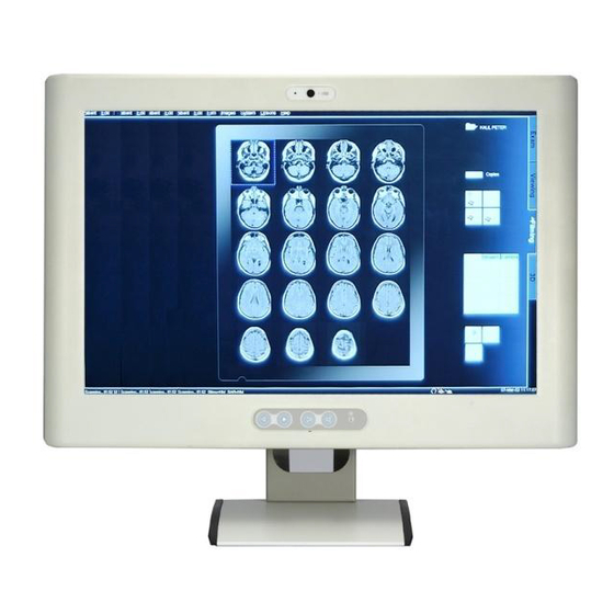
- Page 1 IFO2175-873 Series 17” TFT Fanless Panel Computer ® with Intel Core i7/i5/i3 Processor User’s Manual...
-
Page 2: Disclaimers
AXIOMTEK does not make any commitment to update the information in this manual. AXIOMTEK reserves the right to change or revise this document and/or product at any time without notice. No part of this document may be reproduced, stored in a retrieval system, or transmitted, in any form or by any means, electronic, mechanical, photocopying, recording, or otherwise, without the prior written permission of AXIOMTEK Co., Ltd. -
Page 3: Safety Approvals
Safety Approvals CE Marking FCC Class B FCC Compliance This equipment has been tested in compliance with the limits for a Class A digital device, pursuant to Part 15 of the FCC Rules. These limits are meant to provide reasonable protection against harmful interference in a residential installation. -
Page 4: Safety Precautions
Turn OFF the system power before cleaning. Clean the system using a cloth only. Do not spray any liquid cleaner directly onto the screen. The IFO2175-873 Series may come with or w/o a touchscreen. Although the touchscreen is chemical resistant, it is recommended that you spray the liquid cleaner on a cloth first before wiping the screen. -
Page 5: General Cleaning Tips
General Cleaning Tips You may need the following precautions before you begin to clean the computer. When you clean any single part or component for the computer, please read and understand the details below fully. When you need to clean the device, please rub it with a piece of dry cloth. Be cautious of the tiny removable components when you use a vacuum cleaner to absorb the dirt on the floor. -
Page 6: Scrap Computer Recycling
If the computer equipments need the maintenance or are beyond repair, we strongly recommended that you should inform your Axiomtek distributor as soon as possible for the suitable solution. For the computers that are no longer useful or no longer work well, please contact your Axiomtek distributor for recycling and we will make the proper arrangement. -
Page 7: Table Of Contents
Table of Contents Disclaimers ......................ii Safety Approvals ....................iii Safety Precautions ....................iv Classification ......................iv General Cleaning Tips .................... v Scrap Computer Recycling ..................vi CHAPTER 1 INTRODUCTION ................ 1 General Description ................1 Features ....................1 System Specifications ................ 2 Dimensions .................. - Page 8 APPENDIX A WATCHDOG TIMER ............... 55 About Watchdog Timer ..................55 APPENDIX B INTEL iAMT SETTINGS ............57 Entering MEBx ....................57 Set and Change Password ................58 APPENDIX C INTEL iAMT WEB CONSOLE ..........61 viii...
-
Page 9: Chapter 1 Introduction
IFO2175-873 Series User’s Manual CHAPTER 1 INTRODUCTION This chapter contains general information and detailed specifications of the IFO2175-873 Series. Chapter 1 includes the following sections: General Description Features System Specification Dimensions I/O Outlets Package List... -
Page 10: System Specifications
IFO2175-873 Series Panel PC User’s Manual System Specifications Front Bezel Plastic ABS Display Type 17” SXGA TFT Brightness (Cd/M²) 350 nits LCD Panel Resolution 1280 x 1024 Viewing Angle 80º/60º (H/V) ® Fanless socket rPGA988B 2 & 3 Generation Intel ®... -
Page 11: Dimensions
IFO2175-873 Series User’s Manual Dimensions The following diagrams show you dimensions and outlines of the IFO2175-873 Series. Introduction... -
Page 12: I/O Outlets
IFO2175-873 Series Panel PC User’s Manual I/O Outlets The following figures show you the locations of the IFO2175-873 Series I/O outlets. CONNECTOR Brightness Adjust Buttons Volume Adjust Buttons LED indicator Power on/off button Introduction... -
Page 13: Packing List
Driver/Utility Disc x 1 (For Driver and User’s Manual) Super Multi DVD Cover x 2 (For within Super-multi type) Wall-Mount Bracket x 1 If you can not find this package or any items are missing, please contact AXIOMTEK distributors immediately. Introduction... - Page 14 IFO2175-873 Series Panel PC User’s Manual This page is intentionally left blank. Introduction...
-
Page 15: Chapter 2 Hardware Installation
IFO2175-873 Series User’s Manual CHAPTER 2 HARDWARE INSTALLATION The IFO2175-873 Series are convenient for your various hardware configurations, such as CPU (Central Processing Unit) and HDD (Hard Disk Drive). The chapter 2 will show you how to install the hardware. It includes:... - Page 16 IFO2175-873 Series Panel PC User’s Manual Step 4 Open the back cover and find main board and locate the SO-DIMM socket and CPU cooler. Step 5 Release these screws as marked. Hardware Installation...
- Page 17 IFO2175-873 Series User’s Manual Step 6 Align pins of the CPU with pin holes of the socket. Be careful of the CPU’s orientation that you need to align the arrow mark on the CPU with the arrow key on the socket. Place the CPU into the socket, and use a screwdriver to lock it onto the socket as marked.
- Page 18 IFO2175-873 Series Panel PC User’s Manual Step 8 Push down latches on each side of the SO-DIMM socket. Step 9 Install the memory module into the socket and push it firmly down until it is fully seated. The socket latches are levered upwards and clipped on to the edges of the SO-DIMM.
-
Page 19: Hard Disk Drive Installation
IFO2175-873 Series User’s Manual Hard Disk Drive Installation The IFO2175-873 Series offers a convenient drive bay module for users to install HDD. The system offers users one 2.5” Hard Disk Drive for installation. Please follow the steps: Step 1 Turn off the system, and unplug the Power cord. - Page 20 IFO2175-873 Series Panel PC User’s Manual Step 4 Find the HDD bracket on accessory package and fine HDD socket on main board as marked. Step 5 Use assembly parts to fix HDD with the bracket. HDD Bracket x1 2.5 inch Hard-disk Screw x 4 Fix four screw holes on the bracket, and assembly the HDD with the bracket.
- Page 21 IFO2175-873 Series User’s Manual Step 6 Install the HDD bracket inside the system. Plug the HDD in the SATA connector on main board. Fix two screw holes on main board as marked Step 7 Close the back cover to the chassis, and fasten all screws.
-
Page 22: Serial Ports Interface
IFO2175-873 Series Panel PC User’s Manual Serial Ports Interface The IFO2175-873 series has three serial ports, COM1 (RS-232/ 422/ 485) with isolated 4KV. The following table shows you the pin assignments of this connector: Signal Signal Data Carrier Detect (DCD) -
Page 23: Pcie Mini Card Module Installation
IFO2175-873 Series User’s Manual PCIe Mini Card Module Installation You can follow the steps below to install PCIe mini card modules. Step 1 Turn off the system, and unplug the Power cord. Step 2 Locate and release these screws to open the back cover. - Page 24 IFO2175-873 Series Panel PC User’s Manual Step 4 There are two slots. One is full-size mini card slot which supports mSATA. The other is half-size mini card slot with a SIM card socket. Step 5 The socket latches are clipped on to the edges of the mini card. Install mini card to the socket.
- Page 25 IFO2175-873 Series User’s Manual Step 7 If installing mSATA, please adjust JP3 jumper. Jumper Default Setting Jumper Setting PCIe device (default setting) Short 1-2 mSATA device Short 2-3 Step 8 If installing wireless or 3G module, find the built-in antenna cable and connect it to the connector on wireless or 3G module.
-
Page 26: Add-On Card Installation (Optional)
IFO2175-873 Series Panel PC User’s Manual Add-on card Installation (Optional) You can follow the steps below to install an optional add-on card. Step 1 Turn off the system, and unplug the Power cord. Step 2 Locate and release these screws to open the back cover. - Page 27 IFO2175-873 Series User’s Manual Step 4 Release the screw as marked. And remove plates. Step 5 Insert the add-on card in the socket firmly until it is completely seated. Step 6 Fasten the screw as marked Hardware Installation...
- Page 28 IFO2175-873 Series Panel PC User’s Manual Step 7 Close the back cover to the chassis, and fasten all screws. Please note that users only can install either expansion card or optical drive. Hardware Installation...
-
Page 29: Mount
IFO2175-873 Series User’s Manual Mount There are several mounting ways for the IFO2175-873 Series, Wall mount, VESA and Desktop mountings as below: 2.6.1 Wall mount The mounting for IFO2175-873 Series is W all mount as below: Step 1 Prepare all parts for installing the wall mount kit and assemble the wall mount kit by using screws to fix the backplane. -
Page 30: Desktop Stand (Optional)
IFO2175-873 Series Panel PC User’s Manual 2.6.3 Desktop Stand (Optional) The IFO2175-873 Series provides you with an optional Desktop Stand that you can follow the steps below: Step 1 Prepare the parts of desktop stand. Screw A Screw B Screw C... - Page 31 IFO2175-873 Series User’s Manual Step 3 Assemble the desktop stand by fixing it onto the system. (Use Screw B). Step 4 Assembly the hinge cover and fix the screws as marked on the back side of chassis (Use Screw C).
- Page 32 IFO2175-873 Series Panel PC User’s Manual Step 4 Fix the desktop stand finish. Rear View Front View Hardware Installation...
-
Page 33: Chapter 3 Bios Setup Utility
IFO2175-873 Series User’s Manual CHAPTER 3 BIOS SETUP UTILITY This chapter provides users with detailed description how to set up basic system configuration through the AMIBIOS8 BIOS setup utility. Starting To enter the setup screens, follow the steps below: 1. Turn on the computer and press the <Del> key immediately. -
Page 34: Main Menu
IFO2175-873 Series Panel PC User’s Manual Main Menu When you first enter the setup utility, you will enter the Main setup screen. You can always return to the Main setup screen by selecting the Main tab. System Time/Date can be set up as described below. -
Page 35: Advanced Menu
IFO2175-873 Series User’s Manual Advanced Menu The Advanced menu allows users to set configuration of the CPU and other system devices. You can select any of the items in the left frame of the screen to go to the sub menus: ... - Page 36 IFO2175-873 Series Panel PC User’s Manual ACPI Settings You can use this screen to select options for the ACPI configuration, and change the value of the selected option. A description of the selected item appears on the right side of the screen.
- Page 37 IFO2175-873 Series User’s Manual S5 RTC Wake Setting Use this option to wake on the system on the setting time. W hen enabled System will wake on the time specified BIOS Setup Utility...
- Page 38 IFO2175-873 Series Panel PC User’s Manual CPU Configuration This screen shows the CPU Configuration, and you can change the value of the selected option. Hyper-threading Enabled for W indows XP and Linux and disabled for other OS which do not optimized for Hyper-threating technology.
- Page 39 IFO2175-873 Series User’s Manual SATA Configuration In the SATA Configuration menu, you can see the currently installed hardware in the SATA ports. During system boot up, the BIOS automatically detects the presence of SATA devices. SATA Mode Selection Use this item to choose the SATA operation mode. Here are the options for your selection: IDE Mode and AHCI Mode.
- Page 40 IFO2175-873 Series Panel PC User’s Manual PCH-FW Configuration You can use this screen to confirm ME Firmware version. BIOS Setup Utility...
- Page 41 IFO2175-873 Series User’s Manual USB Configuration You can use this screen to select options for the Isolation USB Configuration, and change the value of the selected option. Isolation USB ports can support two kind of speed: Low Speed / Full Speed. Depending on your speed of USB device, user must select relative USB speed.
- Page 42 IFO2175-873 Series Panel PC User’s Manual NCT6106D Super IO Configuration You can use this screen to select options for the Super IO Configuration, and change the value of the selected option. A description of the selected item appears on the right side of the screen.
- Page 43 IFO2175-873 Series User’s Manual Serial Port 0 Configuration Serial Port Use this item to enable or disable serial port 0. The optimal setting for base I/O address is 3F8h and for interrupt request line is IRQ4. Transmission Mode Use this item to configure serial port 0. Here are the options for your selection:...
- Page 44 IFO2175-873 Series Panel PC User’s Manual NCT6106D HW Monitor This screen shows the Hardware Health Configuration. BIOS Setup Utility...
-
Page 45: Chipset Menu
IFO2175-873 Series User’s Manual Chipset Menu The Chipset menu allows users to change the advanced chipset settings. You can select any of the items in the left frame of the screen to go to the sub menus: ► PCH-IO Configuration ►... - Page 46 IFO2175-873 Series Panel PC User’s Manual PCH-IO Configuration This screen allows users to set PCH parameters. Lanuch PXE OpROM policy Controls the execution of UEFI and Legacy OpROM BIOS Setup Utility...
- Page 47 IFO2175-873 Series User’s Manual System Agent (SA) Configuration This screen shows System Agent information and provides function for specifying related parameters. For items marked with “”, please press <Enter> for more options. VT-d ® Enable or disable Intel chipset virtualization technology for directed I/O. VT-d can help end users improve security and reliability of the systems and also improve performance of I/O devices in virtualized environment.
- Page 48 IFO2175-873 Series Panel PC User’s Manual Graphics Configuration This option allows users to change the integrated graphic device settings. Primary Display Allow you to select which graphics controller to use as the primary boot device. BIOS Setup Utility...
- Page 49 IFO2175-873 Series User’s Manual LCD Control Select LCD panel used by Internal Graphics Device by selecting the appropriate setup item. BIOS Setup Utility...
- Page 50 IFO2175-873 Series Panel PC User’s Manual Memory Configuration This screen displays system memory information. BIOS Setup Utility...
-
Page 51: Boot Menu
IFO2175-873 Series User’s Manual Boot Menu The Boot menu allows users to change boot options of the system. Setup Prompt Timeout Number of seconds to wait for setup activation key. 65535(0xFFFF) means indefinite waiting. Boot Option Priorities These are settings for boot priority. Specify the boot device priority sequence from the available devices. -
Page 52: Security Menu
IFO2175-873 Series Panel PC User’s Manual Security Menu The Security menu allows users to change the security settings for the system. Administrator Password This item indicates whether an administrator password has been set (installed or uninstalled). User Password This item indicates whether an user password has been set (installed or uninstalled). -
Page 53: Save & Exit Menu
IFO2175-873 Series User’s Manual Save & Exit Menu The Save & Exit menu allows users to load your system configuration with optimal or fail-safe default values. Save Changes and Exit When you have completed the system configuration changes, select this option to leave Setup and return to Main Menu. - Page 54 IFO2175-873 Series Panel PC User’s Manual Save Changes When you have completed the system configuration changes, select this option to save changes. Select Save Changes from the Save & Exit menu and press <Enter>. Select Yes to save changes. Discard Changes Select this option to quit Setup without making any permanent changes to the system configuration.
-
Page 55: Chapter 4 Driver Installation
IFO2175-873 Series User’s Manual CHAPTER 4 DRIVER INSTALLATION System IFO2175-873 supports Windows XP/ Windows 7/8 to facilitate the installation of system driver, please carefully read the instructions in this chapter before start installing. Insert Driver Disc in the disk, and select the \IFO2175-873\Driver\.. -
Page 56: Touch Screen
Panel Resistance: 770 ohm) 4.2.2 Driver Installation The IFO2175-873 Series provides a driver of the touch screen that users can install it under operating system Windows XP/7/8. To facilitate this touch screen driver installation, users should read the instructions in this chapter carefully before start the installation. - Page 57 IFO2175-873 Series User’s Manual Click the “Standard Calibration” button. Calibration: To adjust the display with touch panel, click “Calibration” and follow the calibrate point to do calibration; there are five points on screen for calibration. Press OK. Driver Installation...
-
Page 58: Osd Sync Service Install/Uninstall
IFO2175-873 Series Panel PC User’s Manual OSD sync service install/uninstall This OSD sync service can let front OSD key synchronize brightness and volume adjustment with W indows OS and also show OSD notification bar on the screen. 1. Insert Driver CD and select the D:\IFO2175-873\Driver\Step7 - Touch 2. -
Page 59: Led Indicator Status
IFO2175-873 Series User’s Manual LED indicator status Power on(S0): Green Power off(S5): Black LCD off: Orange Touch off: Orange flash OSD & notification bar & setup information W hen pressing front OSD key, OS will show OSD notification status as following. -
Page 60: Uninstall This Service
IFO2175-873 Series Panel PC User’s Manual Uninstall this service 1. double click OSD Sync from programs and features of control panel 2. Choose “Automatically close applications” and click ok Driver Installation... - Page 61 IFO2175-873 Series User’s Manual 3. uninstalling 4. restart computer Driver Installation...
- Page 62 IFO2175-873 Series Panel PC User’s Manual This page is intentionally left blank. Driver Installation...
-
Page 63: Appendix A Watchdog Timer
IFO2175-873 Series User’s Manual APPENDIX A WATCHDOG TIMER About Watchdog Timer Software stability is major issue in most application. Some embedded systems are not watched by human for 24 hours. It is usually too slow to wait for someone to reboot when computer hangs. - Page 64 IFO2175-873 Series Panel PC User’s Manual Digital I/O Software Programming (Following is example to enable configuration by using debug tool) 1.Enable SIO configuration -O 2E 87 -O 2E 87 2. Select Logic device: -O 2E 07 -O 2F 07 3. GPIO2 Enable...
-
Page 65: Appendix B Intel Iamt Settings
IFO2175-873 Series User’s Manual APPENDIX B INTEL iAMT SETTINGS ® ® The Intel Active Management Technology (Intel iAMT) has decreased a major barrier to IT efficiency that uses built-in platform capabilities and popular third-party management and security applications to allow IT a better discovering, healing, and protection their networked computing assets. -
Page 66: Set And Change Password
IFO2175-873 Series Panel PC User’s Manual Set and Change Password You will be asked to set a password when first log in. The default password is “admin”. You will be asked to change the password before setting ME. Intel iAMT Settings... - Page 67 IFO2175-873 Series User’s Manual You must confirm your new password while revising. The new password must contain: (example: !!11qqQQ) (default value). Eight characters One upper case One lower case One number One special symbol, such as ! 、 $ or ; , (、 " , excepted) ...
- Page 68 IFO2175-873 Series Panel PC User’s Manual This page is intentionally left blank. Intel iAMT Settings...
-
Page 69: Appendix C Intel Iamt Web Console
IFO2175-873 Series User’s Manual APPENDIX C INTEL iAMT WEB CONSOLE From a web browser, please type http://(IP ADDRESS):16992, which connects to ® Intel iAMT Web. Example: http://10.1.40.214:16992 To log on, you will be required to type in username and password for access to the Web. - Page 70 IFO2175-873 Series Panel PC User’s Manual Enter the iAMT Web. Click Remote Control, and select commands on the right side. When you have finished using the iAMT Web console, close the Web browser. Intel iAMT Web Console...
Need help?
Do you have a question about the IFO2175-873 Series and is the answer not in the manual?
Questions and answers