Icom IC-7000 Instruction Manual
Hf/vhf/uhf all mode transceiver
Hide thumbs
Also See for IC-7000:
- Instruction manual (166 pages) ,
- Service manual (93 pages) ,
- Manual (34 pages)
Table of Contents
Advertisement
Quick Links
Advertisement
Chapters
Table of Contents
Troubleshooting

Subscribe to Our Youtube Channel
Related Manuals for Icom IC-7000


Summary of Contents for Icom IC-7000
- Page 1 INSTRUCTION MANUAL HF/VHF/UHF ALL MODE TRANSCEIVER i7000...
-
Page 2: Supplied Accessories
Qty. making the IC-7000 your radio of choice, and hope q Hand microphone (HM-151) ....... 1 you agree with Icom’s philosophy of “technology first.” w DC power cable* (OPC-1457) ..... 1 Many hours of research and development went into or (OPC-1457R) .... -
Page 3: Front Panel
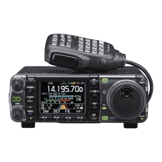
ILLUSTRATIONS Front panel HM-151 ⁄3 ⁄2 SPCH TUNER /LOCK /CALL ⁄1 ⁄0 Mic element MODE GENE F-INP The front panel and HM-151’s panel descriptions are described on pages 1 to 4, and on page 9, respectively (see the Chapter 1 ‘PANEL DESCRIPTION’ for more details). -
Page 4: Table Of Contents
■ Front panel ■ Microphone (HM-151) q AF GAIN CONTROL [AF] (inner control; p. 33) z SPCH/LOCK KEY [SPCH/LOCK] (p. 34, 37) x PTT SWITCH [PTT] (p. 37) w RF GAIN CONTROL/SQUELCH CONTROL [RF/ SQL] (outer control; p. 35) c UP/DOWN SWITCHES [Y]/[Z] e POWER KEY [PWR] (p. -
Page 5: Fcc Information
[DC13.8V] socket on the transceiver rear panel or use reverse manufacturer’s microphones have different pin assignments, polarity. This could cause a fire or damage the transceiver. and connection to the IC-7000 may damage the transceiver. R WARNING! NEVER let metal, wire or other objects touch any internal part or connectors on the rear panel of the transceiver. - Page 6 TABLE OF CONTENTS IMPORTANT ������������������������������������������������������������ i-1 D Differences between VFO and FOREWORD ���������������������������������������������������������� i-1 memory mode ..........26 EXPLICIT DEFINITIONS ���������������������������������������� i-1 ■ VFO operation ..........27 SUPPLIED ACCESSORIES������������������������������������ i-1 D Selecting VFO A/VFO B ....... 27 ILLUSTRATIONS ���������������������������������������������������� i-2 D VFO equalization ..........
- Page 7 TABLE OF CONTENTS 4 Paddle Polarity ........... 50 ■ Noise reduction ..........79 5 Keyer Type ..........50 D Noise reduction Set mode ......79 6 MIC U/D Keyer (HM-103) ......50 ➥ NR Level ........... 79 D Paddle operation from [MIC] connector ..50 ■...
- Page 8 TABLE OF CONTENTS D Selecting a memory channel ■ Quick Set mode ..........121 using the memory channel list ....103 ➥ RF Power (all modes) ......... 121 D Setting a memory channel ➥ MIC Gain (SSB/AM/FM modes) ....121 as a select memory ........
- Page 9 TABLE OF CONTENTS 17 Tuner (Auto Start) ........130 D Codes for memory name contents ..... 147 18 Tuner (PTT start) ........131 D Split/Duplex frequency setting ....147 D Repeater tone/tone squelch frequency 19 [TUNER] Switch ........131 20 VSEND Select ........... 131 setting ............
-
Page 10: E Power Key [Pwr] (P
PANEL DESCRIPTION See the illustration of the Front panel on page i-2. ■ Front panel • When functioning as a squelch control q AF GAIN CONTROL [AF( )] (inner control; p. 33) ➥ Rotate to vary the audio output level from the (RF gain is set at maximum.) speaker or headphones. -
Page 11: U Menu/Group Keys [Menu/Grp] (P
y TWIN PBT (M-ch/RIT) INDICATOR ✔ What is the PBT control? (pp. 73, 77, 86, 100) PBT electronically narrows the IF passband width to reject ➥ Indicates the status of [PBT/M-ch/RIT] (t) as interference. This transceiver uses DSP to implement PBT. the Twin PBT function or memory channel/RIT control. -
Page 12: Manual Notch Key [Mnf/Adj] (P
PANEL DESCRIPTION !0 MANUAL NOTCH KEY [MNF/ADJ] (p. 81) !5 MAIN DIAL TENSION LATCH ➥ Push momentarily to turn the manual notch func- Selects the main dial drag. tion ON or OFF in SSB, CW and AM modes. • Three positions are available. The upper setting turns on •... -
Page 13: Noise Blanker Key [Nb/Adj] (P
PANEL DESCRIPTION !9 TUNING STEP KEY [TS] (pp. 30–32) @2 FUNCTION DISPLAY ➥ While in SSB/CW/RTTY modes, push momentarily Shows the operating frequency, function key menus, to turn the programmable tuning step ON or OFF. simple band scope display, selected memory chan- While in AM/FM/WFM modes, push momentarily nel, etc. -
Page 14: Multi-Function Keys
PANEL DESCRIPTION ■ Multi-function keys D Menu M-2 functions D Menu M-1 functions MEMORY MENU (p. 103) Push momentarily to indicate the mem- SPLIT OPERATION ory frequency and modes. ➥ Push momentarily to toggle the split func- • Memory list indication is available. tion ON or OFF. - Page 15 PANEL DESCRIPTION DURING FM/WFM OPERATIONS: BREAK-IN FUNCTION (p. 85) ➥ Push momentarily to select semi break-in, 9600 full break-in (QSK) and break-in OFF. • “ ” or “ ” appears when selecting semi break-in or full break-in. • An external switch, such as a foot switch, VOX FUNCTION (p.
-
Page 16: D Menu S-1 Functions
PANEL DESCRIPTION D Menu S-1 functions DTMF OPERATION Push to enter DTMF memory mode. DURING SSB/AM OPERATION: (p. 67) • The DTMF send menu or DTMF root menu appears depending on the “DTMF 1st Menu” setting in the miscellaneous (others) Set mode. -
Page 17: D Menu S-3 Functions
PANEL DESCRIPTION D Menu S-3 functions D Menu G-1 (Scope) functions MEMORY WRITE (pp. 101, 102) SWEEP STEPS (pp. 70, 71) Hold down for 1 second to store the dis- ➥ Push momentarily to change the sweep played VFO frequency and operating step. -
Page 18: X Ptt Switch [Ptt] (P
➥ Pushing the same key 2 or 3 times calls up memory channel to the currently displayed VFO. other stacked frequencies in the band. (p. 28) (p. 107) • Icom’s triple band stacking register memorizes 3 ⁄2 TRANSMIT FREQUENCY CHECK [XFC] frequencies in each band. (pp. 65, 89) ➥... -
Page 19: D Microphone Connector
“LOW” level u GND Squelch closed “HIGH” level i Squelch switch CAUTION: NEVER connect or use the supplied HM-151 (microphone) with any other transceiver. This could cause damage to the transceiver. The HM-151 is designed for use with the IC-7000 ONLY. -
Page 20: Rear Panel
➥ Designed for use with a PC to remotely control the transceiver. NOTE: DO NOT use a cigarette lighter socket as a ➥ Used for transceiver operation with another Icom power source when operating in a vehicle. The plug CI-V transceiver or receiver. -
Page 21: D Data Socket
PANEL DESCRIPTION D DATA socket DATA PIN No. NAME DESCRIPTION DATA IN Input terminal for data transmit. (1200 bps: AFSK/9600 bps: G3RUH, GMSK) Common ground for DATA IN, DATA OUT and AF OUT. PTT terminal for packet operation. Connect to ground to activate the transmitter. PTT P When grounded, microphone input (pin 6) of [MIC] connector will be disconnected. -
Page 22: Function Display
PANEL DESCRIPTION • When connecting the ACC conversion cable (OPC-599) Connect to ACC socket ACC 1 ACC 2 9 10 11 12 1 2 3 4 q FSKK t AF q 8 V t ALC w GND y SQLS w GND y VSEND e HSEND u 13.8 V e HSEND... - Page 23 PANEL DESCRIPTION !1 SPLIT INDICATOR (pp. 89, 90) !7 MULTI-FUNCTION SCREEN Appears during split operation. Shows the screens for the multi-function meter, simple band scope, SWR meter, memory channel, !2 IF FILTER INDICATOR (p. 75) voice recorder, memory keyer, DTMF memory Shows the selected IF filter number.
-
Page 24: Installation And Connections
In this case, an antenna tuner is used to match the transceiver and antenna. Low SWR allows full power for transmitting even when using the antenna tuner. The IC-7000 has an SWR meter to monitor the antenna SWR continuously. -
Page 25: Installation
INSTALLATION AND CONNECTIONS ■ Installation D Stand D Single body mounting To raise the stand: Spring washer With the transceiver upside down, pull the stand MB-62 towards the rear panel and then upwards, as (optional) illustrated below. Supplied with the MB-62* then up Pull back Flat washer... -
Page 26: Required Connections
INSTALLATION AND CONNECTIONS ■ Required connections MICROPHONE (p. 10) GROUND (p. 15) heaviest gauge wire or strap available and make STRAIGHT KEY the connection as HM-151 short as possible. Grounding prevents electrical shocks, TVI RTTY TERMINAL and other problems. UNIT (p. 23) DATA ANT2 ANT1... -
Page 27: Advanced Connections
INSTALLATION AND CONNECTIONS ■ Advanced connections HEADPHONES OPC-589 (p. 150) DATA SOCKET (p. 12) 6-pin mini DIN socket to connect to a TNC, etc. for packet operation. SPEAKER VIDEO OUT to [VOUT] jack SM-30 Vout 3.5(d) mm Selectable with the [PHONE/SPEAKER] switch on the back of DESKTOP (p. -
Page 28: Power Supply Connections
• The [POWER] switch is OFF. • Output voltage of the power source is 12–15 V when you use a non-Icom power supply. • DC power cable polarity is correct. : positive + terminal : negative _ terminal Black ■... -
Page 29: Battery Connections
[TRANSCEIVER] Ground Do not connect [ANT2] to the AT- • Turn the IC-7000’s power OFF HF to 2 m/70 cm 1 8 0 . W h e n u s i n g a n H F t o when connecting the AT-180,... -
Page 30: Linear Amplifier Connections
Non-matched ALC and RF power settings could cause a fire or damage the linear amplifier. HSEND The IC-7000 SEND line (ACC connector pin 3) is 50 Ω coaxial cable (Orange) rate at 16 V/200 mA DC. If this level is exceeded, a larger external relay must be used. -
Page 31: Connections For Cw
INSTALLATION AND CONNECTIONS ■ Connections for CW Keyer Set mode (p. 49) [KEY] Rear panel Keyer Set mode setting Paddle polarity Normal Keyer Type ELEC-KEY N o r m a l [ACC] Paddle polarity Reverse Keyer Type ELEC-KEY R ev e rs e For no break-in operation: Paddle Connect an external switch... -
Page 32: Connections For Rtty
INSTALLATION AND CONNECTIONS ■ Connections for RTTY D Connections for RTTY (FSK) Rear panel [ACC] [RTTY] [EXT SP] 2-conductor ˝ plug TNC or PC interface for the RTTY software SEND FSKK 3-conductor ˝ plug (supplied) Rear panel view SQL* (light green) FSKK (black) 9 10 11 AF out (light blue) -
Page 33: Connections For Packet, Sstv Or Psk31
INSTALLATION AND CONNECTIONS ■ Connections for packet, SSTV or PSK31 D When connecting to [DATA] socket TX AUDIO DATA IN Connect SQL line when required. DATA OUT PTTP SQL* RX AUDIO AF OUT [DATA] (Rear panel) RS-232C TNC or PC interface for the software D When connecting to [ACC] socket Rear panel [ACC]... -
Page 34: Basic Operation
BASIC OPERATION ■ When first applying power (CPU resetting) B e fo r e f i r s t a p p l y i n g p o w e r, m a ke s u r e a l l connections required for your system are complete [PWR] by referring to Chapter 2. -
Page 35: Vfo Description
The IC-7000 VFO is somewhat different. The VFO MODE Select display of the IC-7000 acts like a computer’s window and can show one frequency and one operating mode. Change You can call up a desired frequency to the VFO with the memo pad-read key (p. -
Page 36: Vfo Operation
BASIC OPERATION ■ VFO operation D Selecting VFO A/VFO B q Select M-1. Either “ ” or “ ” appears. Menu group selection Hold down [MENU/GRP] for 1 second. Selection from: M, S or G(Graphic) Menu selection (Example: M) Push [MENU/GRP] momentarily. Either Either Selection from: M-1, M-2 or M-3... -
Page 37: Selecting An Operating Band
BASIC OPERATION ■ Selecting an operating band The triple band stacking register provides 3 memories HM-151 in one band. 3 sets of frequency and operating mode on each band are automatically stored when used. SPCH TUNER /LOCK /CALL If a band key (on the HM-151) is pushed once, the last used frequency and operating mode on that band are called up. -
Page 38: Frequency Setting
BASIC OPERATION ■ Frequency setting The transceiver has several tuning methods for convenient frequency tuning. D Tuning with the main dial q Push [Y( )] or [Z( )] to select the band band desired band. Or push the desired band key on the microphone 1–3 times. -
Page 39: D Programmable Tuning Step
BASIC OPERATION D Programmable tuning step The operating frequency can be changed in steps of q Push [TS] momentarily to turn the programmable (0.01 (AM/FM/WFM only), 0.1, 1, 5, 9, 10, 12.5, 20, tuning function ON. 25 or 100 kHz selectable) for quick tuning. •... - Page 40 BASIC OPERATION D Selecting 1 Hz or 10 Hz step (SSB/CW/RTTY only) When neither the quick tuning step or programmable [MODE] [TS] [DIAL] ” appear, rotating [DIAL] changes the tuning step “ frequency in increments of 1 or 10 Hz. These tuning steps are only available in SSB, CW and RTTY modes.
- Page 41 BASIC OPERATION • [TS] switch flow chart SSB/CW/RTTY modes Any mode FM/WFM/AM modes Push Push Appears Appears momentarily momentarily Programmable step tuning 10 Hz tuning 1 MHz tuning SSB/CW/RTTY modes (0.1 kHz –100 kHz) FM/WFM/AM modes (0.01 kHz–100 kHz) 1 sec. 1 sec.
-
Page 42: D Auto Tuning Step Function
BASIC OPERATION D Auto tuning step function When rotating the tuning dial rapidly, the tuning speed accelerates automatically as selected. [AF] q Push [AF( )] momentarily to enter the Set mode menu. w Push [F-4 OTH] to enter the miscellaneous (others) Set mode. -
Page 43: Operating Mode Selection
BASIC OPERATION ■ Operating mode selection The following modes are available in the IC-7000: OPERATING MODE SELECTION SSB (LSB/USB), CW, CW-R (CW reverse), RTTY, RTTY-R (RTTY reverse), AM, FM and WFM (receive Push only). To select the desired mode of operation, push... -
Page 44: Squelch And Receive (Rf) Sensitivity
BASIC OPERATION ■ Squelch and receive (RF) sensitivity [RF/SQL] adjusts the RF gain and squelch threshold [RF/SQL] level. The squelch removes noise output from the speaker (closed position) when no signal is received. • The squelch is particularly effective for FM. It is also available for other modes. -
Page 45: Meter Function
BASIC OPERATION ■ Meter function The transceiver has 4 transmit meter functions for your convenience. Select the desired meter with the DISPLAY [F-3 MET] in the S-1 display. MEASUREMENT INDICATION Indicates the relative RF output power in %. Indicates the SWR on the transmission line. -
Page 46: Lock Functions
BASIC OPERATION ■ Lock functions The lock function can only be activated when displaying frequency, not in Set mode or memory channel listing display. D Dial lock function The dial lock function prevents accidental change caused by [DIAL]. ➥ Hold down [SPCH/LOCK] for 1 second to turn the dial lock function ON or OFF. -
Page 47: D Setting Output Power
BASIC OPERATION D Setting output power q Push [AF( )] momentarily to enter the Set [AF] mode menu. w Push [F-1 QS] to enter the quick Set mode. e Push [F-1 Y] or [F-2 Z] to select “RF Power.” r Rotate [DIAL] to set the desired output setting. •... -
Page 48: Receive And Transmit
RECEIVE AND TRANSMIT ■ Operating SSB q Push [ )]/[ )] to select the desired [AF] [MODE] [TX] indicator band band band or push a band key on the HM-151. w Push [MODE] momentarily or hold down for 1 second to select LSB or USB mode. •... -
Page 49: D Convenient Functions For Transmit
RECEIVE AND TRANSMIT D Convenient functions for transmit • Transmit quality monitor (p. 87) • Speech compressor (p. 87) ➥ Push [AF( )], then [F-4 OTH] to enter the ➥ While “M-3” is selected, push [F-2 COM] to turn miscellaneous (others) Set mode. Select an item the speech compressor ON or OFF. -
Page 50: Operating Cw
RECEIVE AND TRANSMIT ■ Operating CW q Connect a paddle or straight key as on page 22. [AF] [MODE] [TX] indicator w Push [Y( )]/[Z( )] to select the desired band band band or push a band key on the HM-151. e Push [MODE] momentarily to select CW mode. -
Page 51: D Convenient Functions For Receive
RECEIVE AND TRANSMIT D Convenient functions for receive • Preamp and attenuator (p. 72) • Noise blanker (p. 78) ➥ Push [P�AMP/ATT] momentarily to turn the ➥ Push [NB/ADJ] to turn the noise blanker ON or preamp ON or OFF. OFF. -
Page 52: D Cw Reverse Mode
RECEIVE AND TRANSMIT D CW reverse mode The CW-R (CW Reverse) mode receives CW signals [MODE] on the reverse sideband like that of LSB and USB modes. Use when interference is near the desired signal and you want to change the interference tone. q Push [MODE] momentarily several times to select CW mode. -
Page 53: D Cw Pitch Control
RECEIVE AND TRANSMIT D CW pitch control The received CW audio pitch and monitored CW [AF] audio pitch can be adjusted to suit your preferences (300 to 900 Hz) without changing the operating frequency. q When CW (CW-R) mode is selected, enter the quick Set mode. -
Page 54: Electronic Cw Keyer
RECEIVE AND TRANSMIT ■ Electronic CW keyer The IC-7000 has a number of convenient functions [MODE] for the electronic keyer that can be accessed from the memory keyer menu. q Push [MODE] to select CW mode. w Select S-1. (See right page.) e Push [F-2 KEY] to enter the keyer send menu. -
Page 55: D Memory Keyer Send Menu
RECEIVE AND TRANSMIT Menu group selection Hold down [MENU/GRP] for 1 second. Selection from: M, S or G(Graphic) Menu selection (Example: S) Push [MENU/GRP] momentarily. Either Either Selection from: S-1, S-2 or S-3 Y or Z D Memory keyer send menu •... -
Page 56: Ur 5Nn✽ Bk
(“ ” appears next to that channel). select Contents i Repeat steps y and u until the desired contents CQ TEST CQ TEST DE ICOM ICOM TEST are input. o Push [Z( )] to return to memory channel menu/grp UR 5NN✽... -
Page 57: Hold Down [Menu/Grp] For 1 Second Once Or Twice
RECEIVE AND TRANSMIT D Contest number Set mode • Setting the contact (serial) number This menu is used to set the contest (serial) number and incrementing trigger channel, etc. Contact number can be automatically transmitted from one of the memory keyer channels. The Morse [MODE] cut numbers can be used as the contact numbers. -
Page 58: Push [F-1 M1] - [F-4 M4] To Select The Desired
RECEIVE AND TRANSMIT D Keyer Set mode • Setting the electronic keyer This Set mode is used to set the memory keyer repeat time, dash weight, paddle specifications, q Select CW mode with [MODE]. keyer type, etc. w Select S-1. •... -
Page 59: Rise Time
RECEIVE AND TRANSMIT D Keyer Set mode (continued) 3 Rise Time This item sets the envelop rise time during which the • 2, 4, 6, or 8 msec. can be selected. output power reaches the set transmit power. • Hold down [F-4 DEF] for 1 second to select a default setting. -
Page 60: Operating Rtty (Fsk)
RECEIVE AND TRANSMIT ■ Operating RTTY (FSK) When using your RTTY terminal or TNC, consult the [AF] [MODE] [TX] indicator manual that comes with the RTTY terminal or TNC. q Push [Y( )]/[Z( )] to select the desired band band band or push a band key on the HM-151. -
Page 61: D Convenient Functions For Receive
RECEIVE AND TRANSMIT D Convenient functions for receive • Preamp and attenuator (p. 72) • Noise blanker (p. 78) ➥ Push [P�AMP/ATT] momentarily to turn the ➥ Push [NB/ADJ] to turn the noise blanker ON or preamp ON or OFF. OFF. -
Page 62: D Rtty Reverse Mode
RECEIVE AND TRANSMIT D RTTY reverse mode Received characters are occasionally garbled when [MODE] the receive signal is reversed between MARK and SPACE. This reversal can be caused by incorrect TNC connections, settings, commands, etc. To receive a reversed RTTY signal correctly, select RTTY-R (RTTY reverse) mode. -
Page 63: D Functions For The Rtty Decoder Indication
RECEIVE AND TRANSMIT D Function for the RTTY decoder indication The transceiver has an RTTY decoder for Baudot (mark freq.: 2125 Hz, shift freq.: 170 Hz, 45 bps). An external terminal unit (TU) or terminal node controller (TNC) is not necessary for receiving a Baudot signal. -
Page 64: D Rtty Decode Set Mode
RECEIVE AND TRANSMIT D RTTY decode Set mode This Set mode is used to set the decode USOS q Push [MODE] momentarily to select RTTY mode. function, etc. • After RTTY mode is selected, hold down [MODE] for 1 second to toggle between RTTY and RTTY-R modes. w Select S-1. -
Page 65: D Pre-Setting For Using Rtty Terminal Or Tnc
RECEIVE AND TRANSMIT D Pre-setting for using RTTY terminal or TNC When using your RTTY terminal or TNC, consult the manual that comes with the RTTY terminal or TNC. [AF] [MODE] Mark frequency q Push [MODE] momentarily to select RTTY mode. •... -
Page 66: Operating Am
RECEIVE AND TRANSMIT ■ Operating AM [AF] [MODE] [TX] indicator q Push [Y( )]/[Z( )] to select the desired band band band or push a band key on the HM-151. w Push [MODE] momentarily or hold down for 1 second to select AM mode. •... -
Page 67: D Convenient Functions For Transmit
RECEIVE AND TRANSMIT Convenient functions for receive (continued) • DSP noise reduction (p. 79) • Auto notch filter (p. 80) ➥ Push [NR/LEV] to turn the DSP noise reduction ➥ Push [ANF/• REC] to turn the auto notch filter ON or OFF. ON or OFF. -
Page 68: Operating Fm
RECEIVE AND TRANSMIT ■ Operating FM [AF] [MODE] [TX] indicator q Push [ )]/[ )] to select the desired band band band or push a band key on the HM-151. w Push [MODE] momentarily or hold down for 1 second to select FM mode. •... -
Page 69: D Tone Squelch Operation
RECEIVE AND TRANSMIT D Tone squelch operation Tone squelch operation is a method of communications using selective calling. Only received signals having a matching tone will open the squelch. Before communicating using tone squelch, all members of your party must agree on the tone squelch frequency. q Push [MODE] one or more times to select FM mode. -
Page 70: D Dtcs Operation
RECEIVE AND TRANSMIT D DTCS operation DTCS function is an another method of communications using selective calling. Only received signals having a matching 3-digit code will open the squelch. q Push [MODE] one or more times to select FM mode. w Select M-3. -
Page 71: D Tone Scan Operation
RECEIVE AND TRANSMIT D Tone scan operation By monitoring a signal that is being transmitted on a repeater input frequency, you can determine the tone frequency necessary to access a repeater. During tone squelch, DTCS squelch or repeater o p e r a t i o n ( “ ,”... -
Page 72: Repeater Operation
RECEIVE AND TRANSMIT ■ Repeater operation A repeater amplifies received signals and retransmits • To set the transceiver for repeater operation, follow them at a different frequency. When using a repeater, the steps q to e to select VFO mode, desired the transmit frequency is shifted from the receive band, FM mode. -
Page 73: D Repeater Tone Frequency
RECEIVE AND TRANSMIT D Repeater tone frequency Some repeaters require subaudible tones to be accessed. Subaudible tones are superimposed over your normal signal and must be set in advance. The transceiver has 50 tones from 67.0 Hz to 254.1 Hz. E a c h m e m o r y c h a n n e l c a n s t o r e a d i f fe r e n t subaudible tone frequency. -
Page 74: D Transmit Frequency Monitor Check
RECEIVE AND TRANSMIT D Transmit frequency monitor check You may be able to receive the other party’s transmit signal directly (called ‘listening on the repeater input’) without having to go through a repeater. Transmit frequency monitor check (XFC) allows you to check this. -
Page 75: D Storing A Non Standard Repeater
RECEIVE AND TRANSMIT D Storing a non standard repeater Set the frequency. Select [F-1] Set the frequency. [MENU/GRP] [F-2] [F-3] [F-4] [DIAL] q Tur n the auto repeater function OFF in the Select miscellaneous (others) Set mode. (p. 130) Appears w Push [MODE] to select FM mode. -
Page 76: Hz Tone Burst
RECEIVE AND TRANSMIT ■ 1750 Hz tone burst A 1750 Hz tone is required to access most European repeaters. ➥ While holding down [PTT], push [F-3 TON] in the M-1 display during repeater operation. (pp. 63, 66) Popup indication appears. NOTE: This function is not available for non- European versions. -
Page 77: Repeat Steps Y And U Until The Desired Contents
RECEIVE AND TRANSMIT D Programming a DTMF code q Push [MODE] to select FM mode. w Select S-1. • Hold down [MENU/GRP] for 1 second once or twice to select the menu group S. • Push [MENU/GRP] momentarily one or more times to select the menu S-1. -
Page 78: Functions For Receive
■ Simple band scope This DSP-based simple band scope allows you to display conditions on the selected band, as well as relative strength of signals. The IC-7000 has two modes for the spectrum indication—one is fix mode, and another one is center mode. -
Page 79: D Fix Mode
FUNCTIONS FOR RECEIVE D Fix mode Displays signals within the specified frequency range. The selected band conditions can be observed at a glance when using this mode. q Set a mode and frequency. w Select G-1 (Scope). • Hold down [MENU/GRP] for 1 second once or twice [F-1] to select the menu group G (Graphic). -
Page 80: D Center Mode
FUNCTIONS FOR RECEIVE D Center mode Displays signals around the displayed frequency within the selected span. The set frequency is always displayed at the center of the screen. q Set a mode and frequency. w Select G-1 (Scope). • Hold down [MENU/GRP] for 1 second once or twice [F-1] to select the menu group G (Graphic). -
Page 81: Max Hold
FUNCTIONS FOR RECEIVE Scope Set mode (Continued) 1 Max Hold This item turns the peak level holding function ON or OFF. Peak hold is turned ON. Peak hold is turned OFF. (default) 2 Scope Size Normal Wide This item toggles the scope size setting between normal and wide. -
Page 82: Rit Function
FUNCTIONS FOR RECEIVE ■ RIT function The RIT (Receive Incremental Tuning) function [PBT/M-ch/RIT] switch compensates for stations transmitting off-frequency. [RIT] (outer) [PBT/M-ch/RIT] indicator The function shifts the receive frequency up to ±9.999 kHz in 1 Hz steps (10 Hz steps when cancelling the 1 Hz step readout) without moving the transmit frequency. -
Page 83: Agc Function
FUNCTIONS FOR RECEIVE ■ AGC function The AGC (auto gain control) controls receiver gain to The FM/WFM modes AGC time constant is fixed as produce a constant audio output level even when the ‘FAST’ (0.1 seconds) and AGC time constant received signal strength is varied by fading, etc. -
Page 84: If Filter Selection
FUNCTIONS FOR RECEIVE ■ IF filter selection The transceiver has 3 passband IF filter widths for For FM mode, the passband width is fixed and 3 each mode. passband widths are available. For SSB and CW modes, the passband width can be For WFM mode, the passband width is fixed at 280 set from 50 to 3600 Hz in 50 or 100 Hz steps. -
Page 85: D If Filter Shape (Ssb/Cw Only)
FUNCTIONS FOR RECEIVE D FIlter passband width setting (SSB/CW/RTTY/AM only) q Select SSB, CW, RTTY or AM mode. • Passband widths for FM and WFM modes are fixed and cannot be set. w Select M-1. • Hold down [MENU/GRP] for 1 second once or twice to select the menu group M. -
Page 86: Twin Pbt Operation
FUNCTIONS FOR RECEIVE ■ Twin PBT operation T h e g e n e ra l P B T ( Pa s s b a n d Tu n i n g ) f u n c t i o n [PBT (CLR)] switch/[PBT] (inner) control /M-ch/RIT... -
Page 87: Noise Blanker
FUNCTIONS FOR RECEIVE ■ Noise blanker The noise blanker eliminates pulse-type noise [NB/ADJ] Appears such as from car ignitions. The noise blanker is not available for FM/WFM modes. ➥ Push [NB/ADJ] momentarily to toggle the noise blanker ON or OFF. •... -
Page 88: Noise Reduction
FUNCTIONS FOR RECEIVE ■ Noise reduction The noise reduction function enhances desired signals in the presence of noise by using the DSP circuit. The amount of enhancement is adjustable. ➥ Push [NR/LEV] momentarily to toggle the noise reduction ON and OFF. •... -
Page 89: Notch Function
FUNCTIONS FOR RECEIVE ■ Notch function This transceiver has auto and manual notch ➥ While in SSB and AM modes, push [ANF/• REC] functions. The auto notch function automatically or [MNF/ADJ] to toggle the notch function attenuates beat tones, tuning signals, etc., even if between auto, manual and OFF. -
Page 90: D Manual Notch Function
FUNCTIONS FOR RECEIVE D Manual notch function The manual notch function can be used in SSB, CW, RTTY and AM modes. ➥ Push [MNF/ADJ] momentarily to turn the manual notch function ON or OFF. • “ ” appears when manual notch function is in use. •... -
Page 91: Voice Squelch Control Function
FUNCTIONS FOR RECEIVE ■ Voice squelch control function This function is useful when you don't want to hear unmodulated signals. When the voice squelch control function is activated, the transceiver checks received signals for voice components. If a receiver signal includes voice components, and the tone of the voice components changes within 1 second, Appears squelch opens. -
Page 92: Functions For Transmit
FUNCTIONS FOR TRANSMIT ■ VOX function The VOX (Voice-Operated Transmission) function switches between transmit and receive with your voice. This function provides an opportunity for hands-free operation or to input log entries into your computer, etc., while operating. q Select a phone mode (SSB, AM, FM) with Appears [MODE]. -
Page 93: Anti-Vox
FUNCTIONS FOR TRANSMIT D VOX Set mode 1. VOX Gain This item adjusts the VOX gain for the VOX (voice 5 0 % activated transmit) function. This setting can be 50% (default) adjusted from 0 to 100% in 1% steps. •... -
Page 94: D Semi Break-In Operation
■ Break-in function The break-in function is used in CW mode to automatically switch the transceiver between transmit and receive when keying. The IC-7000 is capable of full break-in or semi break-in. D Semi break-in operation • Break-in delay setting... -
Page 95: Tx Function
FUNCTIONS FOR TRANSMIT ■ ∂TX function The ∂TX function shifts the transmit frequency up [PBT/M-ch/RIT] switch to ±9.999 kHz in 1 Hz steps (10 Hz steps when [RIT] (outer) [PBT/M-ch/RIT] indicator cancelling the 1 Hz step readout) without moving the receive frequency. -
Page 96: Speech Compressor
Use headphones to prevent feedback. ■ Speech compressor The IC-7000 has a built-in, low distortion speech compressor circuit. This circuit increases your average talk power in SSB mode and is especially useful for DX-ing or noisy condition when the receiving station is having difficulty copying your signal. -
Page 97: D Compression Level Setting
FUNCTIONS FOR TRANSMIT D Compression level setting • Pre-setting the transceiver • Compression level setting [AF] [MENU/GRP] [F-2] [F-3] [DIAL] [MENU/GRP] [F-1] [F-2] [F-3] [DIAL] q Select an SSB mode. q Select COMP meter. w Turn the speech compressor function OFF, if it’s ●... -
Page 98: Split Frequency Operation
FUNCTIONS FOR TRANSMIT ■ Split frequency operation Split frequency operation allows you to transmit and receive in the same mode on two different frequencies. The split frequency operation is basically performed using 2 VFO frequencies (VFO A and VFO B) on the main and sub readouts. -
Page 99: Quick Split Function
FUNCTIONS FOR TRANSMIT ■ Quick split function W h e n y o u f i n d a D X s t a t i o n , a n i m p o r t a n t [AF] consideration is how to set the split frequency. -
Page 100: D Split Offset Frequency Setting
FUNCTIONS FOR TRANSMIT Menu selection (Example: S-1) • Hold down [MENU/GRP] for 1 second once or twice to select the menu group S. Selection from: M, S or G(Graphic) • Push [MENU/GRP] momentarily one or more times to select the menu S-1. Selection from: S-1, S-2 or S-3 D Split offset frequency setting By setting an often-used split frequency offset in advance, you can operate the quick split function to... -
Page 101: D Spot Measurement
FUNCTIONS FOR TRANSMIT ■ Measuring SWR The IC-7000 has a built-in circuit for measuring The SWR can only be measured on [ANT1] antenna SWR—no external equipment or special connector, in the HF/50 MHz bands when an adjustments are necessary. antenna is connected. However, when a 144/430 MHz antenna is connected to [ANT2], the SWR The IC-7000 can measure SWR in 2 ways—spot... -
Page 102: Recording A Received Audio
VOICE RECORDER FUNCTIONS ■ Digital voice recorder The transceiver has digital voice memories, up Menu group selection to 4 channels for transmit, and up to 99 channels Hold down [MENU/GRP] for 1 second. for receive. A maximum message length of 120 Selection from: M, S or G(Graphic) seconds can be recorded into a receive channel Menu selection (Example: S) -
Page 103: D One-Touch Voice Recording
VOICE RECORDER FUNCTIONS D One-touch voice recording To record the receiving signal contents immediately, one-touch voice recording is available. q Hold down [ANF/• REC] for 1 second while receiving a signal to start recording. • “ ” blinks. • Records audio into the new channel. Blinks w Hold down [ANF/•... -
Page 104: Erasing The Recorded Contents
VOICE RECORDER FUNCTIONS Menu group selection Hold down [MENU/GRP] for 1 second. Selection from: M, S or G(Graphic) Menu selection (Example: S) Push [MENU/GRP] momentarily. Either Either Selection from: S-1, S-2 or S-3 Y or Z ■ Erasing the recorded contents The recorded contents can be erased independently by channel. -
Page 105: Recording A Message For Transmit
VOICE RECORDER FUNCTIONS ■ Recording a message for transmit D Recording To transmit a message using a voice recorder, record the desired message in advance as described below. q Select S-1. w Push [F-1 VO] then [Z( )] to select the menu/grp voice root menu. - Page 106 VOICE RECORDER FUNCTIONS Menu group selection Hold down [MENU/GRP] for 1 second. Selection from: M, S or G(Graphic) Menu selection (Example: S) Either Either Push [MENU/GRP] momentarily. Y or Z Selection from: S-1, S-2 or S-3 ■ Programming a memory name for transmit Memory channels can be tagged with alphanumeric names of up to 5 characters each.
-
Page 107: Sending A Recorded Message
VOICE RECORDER FUNCTIONS ■ Sending a recorded message q Select S-1. w Push [F-1 VO] to call up the voice recorder menu. • If the receive voice memor y channels screen appears, push [Z( )] then push [F-2 TX] to menu / grp select the transmit voice memory channel. -
Page 108: Auto Monitor
VOICE RECORDER FUNCTIONS Menu group selection Hold down [MENU/GRP] for 1 second. Selection from: M, S or G(Graphic) Menu selection (Example: S) Either Either Push [MENU/GRP] momentarily. Y or Z Selection from: S-1, S-2 or S-3 ■ Voice Set mode [MENU/GRP] [F-1] [F-2] [F-4]... -
Page 109: Memory Channels
MEMORY OPERATION ■ Memory channels The transceiver has 501 memory channels including 6 All 503 memory/call channels are tuneable which scan edge channels (3 pairs), and 2 call channels. In means the programmed frequency can be tuned temporarily with [DIAL], etc., in memory mode. addition, a total of 5 memory banks (99 memory channel each), A to E, are available for usage by group, etc. -
Page 110: D Programming In Vfo Mode
MEMORY OPERATION ■ Memory programming Menu group selection Memory channel programming can be performed Hold down [MENU/GRP] for 1 second. either in VFO mode or in memory mode. Selection from: M, S or G(Graphic) Menu selection (Example: M) Either Either Push [MENU/GRP] momentarily. -
Page 111: D Programming In Memory Mode
MEMORY OPERATION D Programming in memory mode [EXAMPLE]: Programming 21.280 MHz/USB into [PBT/M-ch/RIT] switch/[M-ch] (inner) control ch 18. [PBT/M-ch/RIT] indicator [MENU/GRP] [F-2] [F-4] q Push [PBT/M-ch/RIT] momentarily to select the M-ch/RIT function, if the twin PBT is selected. • [PBT/M-ch/RIT] indicator (Green) goes out. w Select M-2. -
Page 112: Memory Channel List
MEMORY OPERATION ■ Memory channel list The memory channel list simultaneously shows 7 Menu group selection memory channels and their programmed contents. Hold down [MENU/GRP] for 1 second. You can select a desired memory channel from the Selection from: M, S or G(Graphic) memory channel list. -
Page 113: D Setting A Memory Channel As A Select Memory
(p. 113) D Selecting a memory bank • Memory channel list indication The IC-7000 has a total of 5 memory banks (99 memory channel each), A to E, available for usage q Select the memory channel list as described at by group, etc. -
Page 114: D Memory Names
MEMORY OPERATION Menu group selection Hold down [MENU/GRP] for 1 second. Selection from: M, S or G(Graphic) Menu selection (Example: M) Push [MENU/GRP] momentarily. Either Either Y or Z Selection from: M-1, M-2 or M-3 D Memory names All memory channels (including scan edges) can [PBT/M-ch/RIT] switch/[M-ch] (inner) control be tagged with alphanumeric names of up to 9 [PBT/M-ch/RIT] indicator... -
Page 115: Memory Clearing
MEMORY OPERATION ■ Memory clearing Any unnecessary memory channels can be cleared. [PBT/M-ch/RIT] switch/[M-ch] (inner) control The cleared memor y channels become blank [PBT/M-ch/RIT] indicator channels. q Select M-2. w Push [F-4 V/M] momentarily to select the memory mode. e Push [PBT/M-ch/RIT] momentarily to select the M-ch/RIT function, if the twin PBT is selected. -
Page 116: Frequency Transferring
MEMORY OPERATION ■ Frequency transferring The frequency and operating mode in a memory Menu group selection channel can be transferred to the VFO. Hold down [MENU/GRP] for 1 second. Frequency transferring can be performed in either Selection from: M, S or G(Graphic) VFO mode or memory mode. -
Page 117: D Transferring In Memory Mode
MEMORY OPERATION D Transferring in memory mode This is useful for transferr ing frequency and [PBT/M-ch/RIT] switch/[M-ch] (inner) control operating mode while operating in memory mode. [PBT/M-ch/RIT] indicator When you have changed the frequency or operating mode in the selected memory channel. •... -
Page 118: Memo Pads
MEMORY OPERATION ■ Memo pads The transceiver has a memo pad function to store frequency and operating mode for easy write and recall. The memo pads are separate from memory channels. The default number of memo pads is 5, however, this can be increased to 10 in the miscellaneous (others) Set mode if desired (p. -
Page 119: D Calling Up A Frequency From A Memo Pad
MEMORY OPERATION D Calling up a frequency from a memo pad You can call up the desired frequency and operating VFO or memory mode mode of a memo pad by pushing [F-3 MPR] in the S-3 menu. • Make sure S-3 is selected in advance. •... -
Page 120: Scan Operation
SCAN OPERATION ■ Scan types PROGRAMMED SCAN PRIORITY WATCH Repeatedly scans between two scan edge frequencies Checks for signals on a memory while operating on a (scan edge memory channels 1A and 1B). VFO frequency. Scan Scan edge 1A or 1B Scan edge 1B or 1A Memory frequency... -
Page 121: Programmed Scan Operation
SCAN OPERATION Menu group selection Hold down [MENU/GRP] for 1 second. Selection from: M, S or G(Graphic) Menu selection (Example: M) Push [MENU/GRP] momentarily. Either Either Selection from: S-1, S-2 or S-3 Y or Z ■ Programmed scan operation q Select S-2. w Push [F-3 V/M] to select VFO mode. -
Page 122: Select Memory Scan Operation
SCAN OPERATION Menu group selection Hold down [MENU/GRP] for 1 second. Selection from: M, S or G(Graphic) Menu selection (Example: M) Push [MENU/GRP] momentarily. Either Either Selection from: S-1, S-2 or S-3 Y or Z ■ Select memory scan operation q Select S-2. -
Page 123: Antenna Tuner Operation
• The AT-180 can match both HF and 50 MHz bands. However, operation is different for the HF and 50 MHz bands. • When connecting the AT-180, the IC-7000’s output power must be set over the 10 W. Otherwise, the AT-180 may not be tuned correctly. (AT-180’s minimum operating input power is 8 W.) -
Page 124: D Ah-4 Operation
Y or Z ■ Optional AH-4 operation automatic antenna tuner The AH-4 matches the IC-7000 to a long wire antenna RDANGER!: HIGH VOLTAGE! more than 7 m/23 ft long (3.5 MHz and above). • See page 20 for connection. NEVER touch the antenna element while tuning or •... -
Page 125: Packet Operation
Vp-p, otherwise the transceiver will not be able to 2. When not using a measuring device. maintain the band width and may possibly interfere q Connect the IC-7000 to a TNC. with other stations. w Enter a test mode (“CAL”, etc.) on the TNC, then transmit some test data. -
Page 126: Clock And Timers
CLOCK AND TIMERS ■ Time Set mode This transceiver has a built-in 24-hour clock (accuracy q Push [AF( )] momentarily to enter the Set mode ±75 seconds per month) with power-off timer function. menu. The clock indication is always displayed except after w Push [F-3 TIME] to enter the time Set mode. -
Page 127: D Setting The Current Year
CLOCK AND TIMERS D Setting the current year w Set the current year using [DIAL]. q Entering time Set mode, push [F-1 ≤] to select “Year” item. • “Push [SET]” blinks. e Push [F-3 SET] to enter the set year. •... -
Page 128: D Clock2 Function Activity
CLOCK AND TIMERS D Clock2 function activity q Entering time Set mode, push [F-1 ≤] or [F-2 ≥] to select “CLOCK2 Function” item. w Select the CLOCK2 function activity using [DIAL]. e Push [Z( )] twice to exit time Set mode. menu/grp D Clock2 offset setting q Entering time Set mode, push [F-1 ≤] or [F-2 ≥]... -
Page 129: Set Mode
SET MODE ■ Set mode description Set mode is used for programming infrequently q Push [AF( )] momentarily to enter the Set mode changed values or conditions of functions. This trans- menu. ceiver has a quick Set mode, display Set mode, timer w Push [F-1 QS], [F-2 DISP], [F-3 TIME] or [F-4 Set mode and miscellaneous (others) Set mode. -
Page 130: Quick Set Mode
SET MODE ■ Quick Set mode Mode Set mode item Default setting 100% RF Power MIC Gain 100 [Hz] SSB TBW (WIDE) L 2900 [Hz] SSB TBW (WIDE) H 300 [Hz] SSB TBW (MID) L 2700 [Hz] SSB TBW (MID) H 500 [Hz] SSB TBW (NAR) L 2500 [Hz]... -
Page 131: Key Speed (Cw Mode)
SET MODE ■ Quick Set mode (continued) SSB TBW (WIDE) H (SSB mode) These items set the transmission passband width 2 9 0 0 for the wide setting by selecting the lower and higher 2900 Hz (default) frequencies. Higher freq. : 2500, 2700, 2800 and 2900 Hz (default) SSB TBW (MID) L (SSB mode) These items set the transmission passband width for... - Page 132 SET MODE ■ Quick Set mode (continued) Side Tone Level (CW mode) This item adjusts the CW side tone level from 0% to 5 0 % 100% in 1% steps. 50% (default) See p. 43 for details. Side Tone Level Limit (CW mode) This item allows you to set a maximum volume level for CW side tones.
-
Page 133: Display Set Mode
This item adjusts the flicker of the LCD from 0% to 100% in 1% steps. 6 5 % 65% (default) Icom recommends using the default value. But if you find the LCD flicker objectionable, adjust this item. 5 Backlight(Switches) This item adjusts the brightness of the switches from ... -
Page 134: Display Font Type
SET MODE ■ Display Set mode (continued) 7 Display Font Type This item sets the font type of the frequency read- Basic outs. Basic and Italic (2 fonts) are selectable. Basic font (default) 8 Display Font Size This item sets the font size of the frequency read- Normal outs. -
Page 135: Tv Popup (P.amp/Att)
SET MODE ■ Display Set mode (continued) 14 TV Popup (CH Up/Down) This item turns the popup indication ON or OFF for the TV channel Up/Down operation. Popup function is ON Popup function is OFF TV operation is available for Japanese version only. (default) 15 TV Popup (P.AMP/ATT) This item turns the popup indication ON or OFF for... -
Page 136: Power On Check
SET MODE ■ Display Set mode (continued) 21 My Call r Input the desired character by rotating [DIAL] or by pushing the band key (on HM-151) for number Your call sign, etc. can be displayed in the opening input. screen when turning power ON. Up to 10 characters •... -
Page 137: Miscellaneous (Others) Set Mode
SET MODE ■ Miscellaneous (others) Set mode 1 Monitor This item sets the TX monitor function ON or OFF. T X m o n i t o r f u n c t i o n i s T X m o n i t o r f u n c t i o n i s The monitor gain can be set described below. -
Page 138: Rf/Sql Control
SET MODE ■ Miscellaneous (others) Set mode (continued) 7 RF/SQL Control The [RF/SQL] control can be set as the RF/squelch [RF/SQL] control as RF/squelch control RF+SQL control (default), the squelch control only (RF gain is [RF/SQL] control as squelch control fixed at maximum) or ‘Auto’... -
Page 139: Dup Offset 144M
SET MODE ■ Miscellaneous (others) Set mode (continued) 13 DUP Offset 144M This item sets the offset (difference between transmit 0.600MHz and receive frequencies) for duplex operation. How- 0.6 MHz offset (default) ever, this setting is used to input the repeater offset for an 144 MHz band only. -
Page 140: Tuner (Ptt Start)
SET MODE ■ Miscellaneous (others) Set mode (continued) 18 Tuner (PTT Start) When an optional AH-4 is con- antenna tuner nected, tuning can be started automatically at the Tuning starts when pushing Tuning star ts only when moment the PTT is pushed. [TUNER] is pushed. -
Page 141: Speech S-Level
SET MODE ■ Miscellaneous (others) Set mode (continued) 24 SPEECH S-Level You can have frequency, mode and signal level an- nouncement. Signal level announcement can be de- Signal level announcement No signal level activated if desired. announcement (default) When “OFF” is selected, the signal level is not an- nounced. -
Page 142: Hm-151 [F-1]
SET MODE ■ Miscellaneous (others) Set mode (continued) 30 HM-151 [F-1] This item programs one of several functions to [F-1] key of HM-151. Programmable key assignments are Memo pad wr ite is pro - Auto notch filter is pro- described as below. grammed. -
Page 143: Cw Normal Side
SET MODE ■ Miscellaneous (others) Set mode (continued) 35 CW Normal Side Selects the carrier point of CW mode from LSB and USB. The carrier point is set to The carrier point is set to LSB side. USB side. (default) 36 VOICE 1st Menu This item selects the initial menu when [F-1 VO] VOICE-RX/TX... -
Page 144: Mode Select (Wfm)
SET MODE ■ Miscellaneous (others) Set mode (continued) 42 Mode Select (AM) This item inhibits the selection of AM mode, and al- lows you to simplify operation during normal opera- AM mode is selectable. AM mode is inhibited. tion. (default) 43 Mode Select (FM) This item inhibits the selection of FM mode, and al- lows you to simplify operation during normal opera-... -
Page 145: Front Keypad Type
Address of 70h Address of 7Fh The IC-7000’s address is 70h. (default) When 2 or more IC-7000’s are connected to an op- , rotate [DIAL] tional CT-17 v level converter to select a different address for each IC-7000 in the range 01h to 7Fh. -
Page 146: Maintenance
• Circuitry fuse .......... ATC20 5 A CIRCUITRY FUSE REPLACEMENT The 13.8 V DC from the DC power cable is applied to all units in the IC-7000, except for the power am- plifier, through the circuitry fuse. This fuse is installed in the FRONT unit. -
Page 147: Troubleshooting
The following chart is designed to help you correct If you are unable to locate the cause of a problem problems which are not equipment malfunctions. or solve it through the use of this chart, contact your nearest Icom Dealer or Service Center. PROBLEM POSSIBLE CAUSE SOLUTION REF. -
Page 148: Troubleshooting
TROUBLESHOOTING PROBLEM POSSIBLE CAUSE SOLUTION REF. The operating frequency is not set to Transmitting is impos- Set the frequency to a ham band. p. 29 sible. a ham band. p. 38 Output power is too low. Power is set to a lower power than Set the output power in quick Set maximum. -
Page 149: Mb-106 Carrying Handle
The band voltage appears on pin 5 of [ACC] connector after modification is completed. Cooling Performing this modification is the customer’s re- sponsibility. Icom does not guarantee this modifi- Front panel cation’s result. CAUTION: Disconnect the DC power cable... -
Page 150: At-180 Internal Switch Description
OPTION UNITS SETTING ■ AT-180 internal switch description The optional AT-180 has 3 operating configurations for HF band operation. Select a suitable configura- tion according to your antenna system. • Specifications for the AT-180 q Remove the top cover of the AT-180. •... -
Page 151: Control Command
RS-232C port. The Icom Communication inter- face-V (CI-V) controls the following functions of the transceiver. Up to four Icom CI-V transceivers or receivers can be connected to a PC equipped with an RS-232C port. See page 136 for setting the CI-V condition using the miscellaneous (others) Set mode. - Page 152 CONTROL COMMAND • Command table (continued) Command Sub command Description Command Sub command Description Set as non-select channel 17 + Level data Anti-VOX gain setting (0=0 to Set as select channel 255=100%) Set scan resume OFF 18 + Level data Contrast (LCD) setting (0=0 to Set scan resume ON 255=100%) 19 + Level data B r i g h t ( L C D ) s e t t i n g ( 0 = 0 t o...
- Page 153 CONTROL COMMAND • Command table (continued) Command Sub command Description Command Sub command Description 050007 Send/read of SSB TX bandwidth 050036 Send/read opening message (lower edge) for narrow (0=OFF, 1=ON) (0=100, 1=200, 2=300, 3=500 HZ) 050037 Send/read my call sign setting (10 050008 Send/read of SSB TX bandwidth character: see page 147 )
- Page 154 CONTROL COMMAND • Command table (continued) Command Sub command Description Command Sub command Description 050063 Send/read [TUNER/CALL] key 050087 Send/read FM mode selectability action set (0=Manual, 1=Auto) ( 0=OFF: inhibition, 1=ON: selectable) 050064 Send/read [ACC] (pin 7) output “VSEND” set (0=OFF, 1=UHF 050088 Send/read WFM mode only, 2=ON)
-
Page 155: D To Send/Read Memory Contents
CONTROL COMMAND • Command table (continued) D To send/read memory contents When sending or reading memory contents, an additional Command Sub command Description code as follows must be added to specify the memory 050114 Send/read NR level set channel. (0=0 to 15=15) ➥... -
Page 156: D Character Codes For My Call
CONTROL COMMAND D Character codes for My Call D Split/Duplex frequency setting The following data sequence is used when sending/reading Character ASCII code Description the split or duplex frequency setting. 0–9 30–39 Numerals A–Z 41–5A Alphabetical characters space Word space –... -
Page 157: Specifications
SPECIFICATIONS ■ General ■ Receiver • Frequency coverage : • Receive system Receive SSB/CW/RTTY/AM/FM Triple-conversion superheterodyne 30 kHz – 199.999999 MHz* WFM Double-conversion superheterodyne 400– 470.000000 MHz* • Intermediate frequencies: Transmit 1.800–1.999999 MHz* , 3.500–3.999999 MHz* SSB/CW/RTTY/AM/FM 124.487 MHz 5.33050* , 5.34650* , 5.35700* 134.732 MHz... -
Page 158: Options
OPTIONS AT-180 AH-4 AH-2b HF/50 MHz AUTOMATIC HF AUTOMATIC ANTENNA ANTENNA ELEMENT ANTENNA TUNER TUNER A 2.5 m long antenna element for mobile op- eration with the AH-4. • Frequency coverage 7–54 MHz band with the AH-4 Fully automatic antenna tuner with preset Specially designed to tune a long wire memor ies for each 100 kHz. -
Page 159: Options
Conversion between 8-pin modular and Convenient when carrying the transceiver. Allows you to conveniently vehicle-mount the 8-pin metal connector for using a desktop front panel of the IC-7000. An MB-105 must microphone with the IC-7000. be used in combination with the MB-120. OPC-599... - Page 160 MENU GUIDE Main menu group Sub menu group SPL A/B FIL MET VSC (SSB/AM) MEM MW MCL (CW) VO KEY MET VSC (RTTY) VO DEC MET VSC VOX COM AGC (SSB) VO DTM MET VSC (CW) 1/4 AGC (FM/WFM) (RTTY) SCN PRI V/M VSC (AM)
- Page 161 MENU GUIDE Set mode description • Set mode menu • Miscellaneous (others) Set mode Push [Z( )] or [AF] switch MENU/GRP to return to upper menu • Display Set mode • Time Set mode Quick Set mode RTTY AM/FM mode mode mode mode...
-
Page 162: Installation Notes
Further information can Versions of the IC-7000 which display the be found at http://www.arrl.org/. “CE” symbol on the serial number label, comply with the essential requirements of •... - Page 163 ABOUT CE DECLARATION OF CONFORMITY We Icom Inc. Japan 1-1-32, Kamiminami, Hirano-ku Osaka 547-0003, Japan Declare on our sole responsibility that this equipment complies with the sseldorf 21st Nov. 2005 ü essential requirements of the Radio and Telecommunications Terminal Equipment Directive, 1999/5/EC, and that any applicable Essential Test Suite measurements have been performed.
- Page 164 MEMO...
- Page 165 MEMO...
- Page 166 ■ ■ ■ ■ (UK) ■ ■ ■ ■ ■ GBR ■ ■ ■ ■ ■ ■ ■ ■ A-6478H-1EX-t Printed in Japan © 2005–2010 Icom Inc. 1-1-32 Kamiminami, Hirano-ku, Osaka 547-0003, Japan Printed on recycled paper with soy ink.
Need help?
Do you have a question about the IC-7000 and is the answer not in the manual?
Questions and answers