Table of Contents
Advertisement
Quick Links
Advertisement
Table of Contents

Related Manuals for Intergraph StudioZ GT RAX

Summary of Contents for Intergraph StudioZ GT RAX
- Page 1 GT RAX Systems System Setup April 1999 D1AA00090...
- Page 2 Computer Systems shall not be liable for incidental or consequential damages resulting from the furnishing or use of this document. All warranties given by Intergraph Computer Systems about equipment or software are set forth in your purchase contract. Nothing stated in, or implied by, this document or its contents shall be considered or deemed a modification or amendment of such warranties.
-
Page 3: Table Of Contents
Ergonomic Information ......................... viii Customer Support.......................... viii Hardware and Software Support Services ............... viii World Wide Web ......................ix Intergraph Bulletin Board Service..................ix Telephone.......................... ix More Support Options......................x 1 Setting Up the Hardware ......................1 Unpacking the System ........................2 Observing Safety Precautions...................... - Page 4 Configuring RAID Disk Drives ...................... 29 Changing Drive Letters........................30 Changing Virtual Memory Settings ....................31 Configuring the Symbios SCSI Controllers..................32 Creating an Emergency Repair Disk....................33 Getting Operating System Updates....................34 4 Operating Notes......................... 35 Starting and Stopping the System ....................36 Observing Operating Precautions ....................
- Page 5 Boot ..............................57 Floppy Check ........................57 Summary Screen....................... 58 Boot Device Priority ......................58 Hard Drive........................58 QuietBoot ......................... 58 Multiboot.......................... 58 Security............................58 Set Supervisor Password ....................59 Set User Password......................59 Password on Boot......................59 Exit Screen ............................. 59 Updating the System BIOS......................
-
Page 7: Preface
Preface This System Setup document describes setting up, configuring, and reinstalling system software on your Intergraph Computer Systems rack-mount GT RAX system. This document supports the following RAX systems: StudioZ GT RAX for SOFTIMAGE|DS StudioZ GT for SynaFlex ViZRAX-GT About This Document This System Setup document is organized as follows: Chapter 1, “Setting Up the Hardware,”... -
Page 8: Operating System Information
This includes World Wide Web access, Intergraph Bulletin Board Service access, and telephone (Help Desk) support. At the end of the complimentary support period, you can purchase other levels of software support. -
Page 9: World Wide Web
On these pages, you can get news and product information, technical support information, software updates and fixes, and more. Intergraph Bulletin Board Service On the Intergraph Bulletin Board Service (IBBS), you can get technical support information, software updates and fixes, and more. NOTE Most of the system software for your StudioZ GT RAX system can be found in the TDZ 2000 GT1 area of the IBBS. -
Page 10: More Support Options
Visit the Support pages on the World Wide Web at http://www.intergraph.com/ics. For hardware support questions in the United States, call 1-800-763-0242. For software support questions in the United States, call 1-800-345-4856. Outside the United States, contact your local Intergraph Computer Systems subsidiary or distributor. -
Page 11: Setting Up The Hardware
Setting Up the Hardware This chapter provides instructions for setting up and installing the rack-mount base unit for your GT RAX system into a standard equipment rack. Refer to the documentation delivered with the rack for instructions to unpack it and set it up. Unpacking the System ........................ -
Page 12: Unpacking The System
Keyboard and mouse Windows NT operating system software (CD-ROM and diskettes) and documentation Intergraph system software for Windows NT (diskettes) If you purchased a monitor from Intergraph Computer Systems, its carton contains the following: Monitor and power cord Video cable... -
Page 13: Observing Safety Precautions
Observing Safety Precautions WARNING Follow all instructions explicitly to avoid personal injury and equipment damage. Before installing the base unit into a rack, prevent the rack from moving by engaging the stabilizers. If the rack is not equipped with stabilizers, refer to the documentation delivered with the rack for stabilizing instructions. -
Page 14: Understanding Vertical Units
Understanding Vertical Units You can identify a vertical unit (U) mark as a round hole along the edge of the side rails. Note that it is smaller than the mounting holes used to secure equipment in a rack. The 40 U rack additionally uses a square hole to indicate every fourth vertical unit. - Page 15 Install the handle brackets on the base unit, using the screws provided. Base Unit Rail Guide Handle Brackets If the rail guides are already attached to the base unit, skip to step 4. If the rail guides are not attached to the base unit, do the following: Remove the rail guides from the mounting rails.
- Page 16 Use the button-head screws and bolts provided to loosely secure the rail brackets to the rack rails. See the following figure. The rail brackets have the rail teeth needed to secure the rack rails to the back of the rack. Install the button-head screws and bolts loosely so you can adjust the back rail teeth positions as needed in step 8.
- Page 17 Mounting Holes Bar Nut Flat-Head Screws Teeth Rack Rail Slide tinnerman nuts over the third and thirteenth mounting holes starting from the bottom of the 5 Us. The tinnerman nuts will be used when you secure the handle brackets on the front of the base unit to the front of the rack.
- Page 18 Bar Nut Mounting Holes Button-Head Teeth Screws Rack Rail Tighten the screws on the rail brackets on each rack rail in the back of the rack. 10. Extend the rails from the rack until they lock. 11. With a person on each side, lift the base unit and align the rack rails with the rail guides mounted on the side of the base unit.
-
Page 19: Connecting The Cables
Connecting the Cables All cable ports on the base unit and other Intergraph Computer Systems equipment are keyed or molded and labeled to ensure proper cable attachment. If a cable is not attaching easily, ensure that you are aligning the cable connector correctly with the port. - Page 20 The base unit ports are labeled for easy reference. Refer to the following table as needed when connecting cables to the base unit. Connect the cable from this… …To this port Port Description Monitors or monitor cables from cable Video Out ports on the graphics extension console controller cards Mouse or mouse cable from cable...
- Page 21 To connect the cables: Connect the video cables from the monitors (or the equivalent cables from cable extension consoles) to the video out ports on the graphics controller cards in the expansion slots. See the graphics controller documentation for more information. Connect the cables for the mouse and keyboard (or the equivalent cables from a cable extension console) to their ports on the I/O panel.
-
Page 22: Installed Expansion Cards
Installed Expansion Cards Expansion cards are installed as needed in the Accelerated Graphics Port (AGP), Peripheral Component Interconnect (PCI), and Industry Standard Architecture (ISA) expansion slots in the base unit. The layout of expansion slots, and the location of typical expansion cards installed in a GT RAX system, is as follows: Slot Type... - Page 23 The disk drive bay can contain up to four 3.5-inch removable SCSI disk drives. Depending on your system configuration, these drives may be JBOD (for “just a bunch of disks”) or RAID (for “redundant array of independent disks”) drives. Each removable disk drive has a Single Connection Attach (SCA) connector that provides for easy removal and replacement of the drive.
-
Page 24: Connecting An External Scsi Device
To install removable disk drives in the disk drive bay: Open the disk drive bay door on the front of the base unit. The key is in the parts box. Take the removable disk drives from their carton and place them on an antistatic surface. Carefully open the antistatic bags and remove the drives. - Page 25 To ensure data integrity and optimum performance, do the following: The maximum speed of a SCSI bus is limited to the speed of the slowest device on that bus. Use only Intergraph Computer Systems SCSI cables. Cables from other vendors may not provide adequate shielding.
-
Page 26: Checking The System
Checking the System Before starting the system, review the following items: All hardware is properly and securely installed in the rack. The cables are properly attached to the base unit, and there is enough slack cable to allow the base unit to extend from the rack. The cables that run along the sides or top of the rack have clips or ties to secure them in place. -
Page 27: What's Next
You can do any of the following to prepare your system for use: If you want to get going with Intergraph’s default setup, go to Chapter 2, “Setting Up the Software,” to start the system and go through Windows NT Setup. If you start the system, and then turn it off before completing the instructions in Chapter 2, you will have to reinstall the operating system and associated system software. -
Page 29: Setting Up The Software
Setting Up the Software Follow the instructions in this chapter to set up the operating system and associated system software for your GT RAX system. Preparing for System Software Setup ..................... 20 Starting Operating System Setup ....................21 Finishing System Software Setup ....................23 Creating an Emergency Repair Disk ................ -
Page 30: Preparing For System Software Setup
The latest certified Windows NT Service Pack software Quick-Fix Engineering (QFE) software, if needed InterSite software Intergraph Computer Systems installs the operating system through Phase I of the operating system Setup process. You must follow the operating system Setup process to prepare Microsoft Windows NT for use. -
Page 31: Starting Operating System Setup
If the system is connected to a network, get and record the following information for your system from your network administrator: Computer name: Workgroup name (if the system will be part of a workgroup): Domain name (if the system will be part of a Windows NT domain): If the system is connected to a network that uses the Transmission Control Protocol/Internet Protocol (TCP/IP), get and record the appropriate TCP/IP information for your system from your... - Page 32 Power Button The first time you start the system, it boots to a Microsoft End User License Agreement (EULA). After reading and accepting the terms of the agreement, follow the instructions to continue operating system Setup. Take the default settings provided by Setup, except as noted in the following text.
-
Page 33: Finishing System Software Setup
Welcome to get the latest driver and other system software from the World Wide Web, and to learn about Intergraph Computer Systems customer support. You should take advantage of the tools provided by InterSite Welcome to ensure that your system is fully ready for use. -
Page 34: Creating System Software Backup Diskettes
CD-ROM or on backup diskettes delivered with expansion cards. See Version Manager Help for information on creating system software backup diskettes. Visit the Intergraph Computer Systems site on the World Wide Web and vendor bulletin boards for new and updated drivers. -
Page 35: Configuring The System
Configuring the System Follow the instructions in this chapter to configure your GT RAX system for use. This chapter covers items required for basic operation. Configuring the Video Display....................... 26 Resetting the Video Display Resolution................26 Changing the Default Video Display Driver ..............26 Correcting Video Display Problems................. -
Page 36: Configuring The Video Display
Changing the Default Video Display Driver After configuring the video display and restarting the system, you should configure the system to use the Intergraph video display driver by default. To change the default video display driver: Open System in the Windows NT Control Panel. The System dialog displays. -
Page 37: Correcting Video Display Problems
A multi-sync monitor is selected, but a graphics display device with different video timings (such as an Intergraph InterVue monitor) is connected to the system. Select the appropriate monitor type as described previously. The monitor selection is inappropriate for the monitor connected to the system. Select a new monitor. -
Page 38: Configuring Audio
Configuring Audio If your system has an audio controller card in the expansion slots, see the audio controller documentation for information on configuring system audio. The system is equipped with an Ensoniq ES1371 AudioPCI sound controller on the system board. If the system has a microphone and speakers connected to the ports on the I/O panel, you can use the Ensoniq AudioPCI Mixer to control the volume and to select the recording input device. -
Page 39: Configuring Jbod Disk Drives
CH means the RAID SCSI bus channel of the adapter (each adapter has two channels). ID means the identification number of the drive in the slot. NOTE When the standard disk drives are configured by Intergraph Computer Systems (as described below), they assume the ID number of the internal disk section slot. -
Page 40: Changing Drive Letters
Three or four RAID disk drives may be installed and configured with the Mylex RAID controller software at the factory. These RAID disk drives are configured to appear as one logical drive in Windows NT Disk Administrator. The logical drive has a 2 GB NTFS system disk partition. The rest of the logical drive is formatted as one NTFS partition, for a total of two partitions. -
Page 41: Changing Virtual Memory Settings
From the Tools menu, click Assign Drive Letter. NOTE If you select the current drive or an otherwise locked drive, you must restart the system to complete the drive letter reassignment. Select a new drive letter to assign to the drive from the list. Click OK, and then click Yes to continue. -
Page 42: Configuring The Symbios Scsi Controllers
You may need to change SCSI controller parameters on a per-device basis under the following conditions: If you are advised to do so by Intergraph Computer Systems technical support or instructed to do so by the vendor documentation supplied with the SCSI device. -
Page 43: Creating An Emergency Repair Disk
To change the synchronous data transfer rate: Run the SCSI Configuration Utility as described previously. From the main menu, select the SCSI controller (or host adapter) that you want to configure and press . Three SCSI controllers are listed, as follows: ENTER Two SYMB53C896 LVDS Wide Ultra2 SCSI controllers, one for each channel, are listed. -
Page 44: Getting Operating System Updates
You can get then from Microsoft’s World Wide Web and FTP sites free of charge. CAUTION If Intergraph Computer Systems provides a Service Pack through the IBBS or with a product, it has been certified against Intergraph Computer Systems hardware as described in the announcement of its availability. -
Page 45: Operating Notes
Operating Notes This chapter contains important, basic information on operating your GT RAX system. Starting and Stopping the System ....................36 Observing Operating Precautions ....................38 Booting the System from a CD-ROM..................... 38 Using the Keyboard ........................39 Using the Mouse..........................40 Using the Floppy Disk Drive ...................... -
Page 46: Starting And Stopping The System
Starting and Stopping the System When you connect the power cord from the system to an AC power outlet, auxiliary power is applied to the system. This auxiliary power is available for the system to monitor, among other things, the Power button. The power LED lights amber to note the presence of auxiliary power. Power Button Power LED Reset Button... - Page 47 CAUTION Be sure to select Shut Down from the Start menu, and then select the shutdown option, before powering off the system with the Power button. Powering off the system simply by using the Power button can cause data loss and/or file corruption. See the following table for details on using the Power button.
-
Page 48: Observing Operating Precautions
To boot the system from a bootable CD-ROM: Insert the bootable CD-ROM in the system’s CD-ROM drive. Restart the system. As the system boots -- for example, during the memory test or when the Intergraph Computer Systems logo displays -- press NOTE You must press to ensure the system’s CD-ROM drive displays as a boot device. -
Page 49: Using The Keyboard
Using the Keyboard NOTE If you use a concentrator to connect several systems to a single keyboard, mouse, and monitor, you may not have purchased a keyboard with each system. The system’s keyboard includes the following features: 104 standard keys, including special application function keys ( 1 through 12), arrow keys for moving the cursor, and numeric keys in a keypad. -
Page 50: Using The Mouse
Using the Mouse The system’s mouse is a PS/2-compatible tracking device that controls the movement and positioning of the pointer (or cursor) displayed on the screen in a graphical display environment. The basic techniques for using the mouse are as follows: Action Description Point... -
Page 51: Using The Cd-Rom Drive
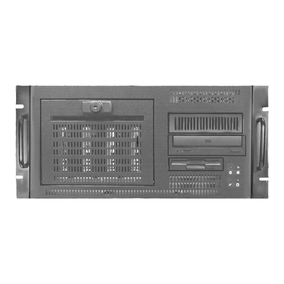
Floppy Disk Drive CD-ROM Drive Using the CD-ROM Drive The system’s CD-ROM drive occupies a 5.25-inch external peripheral device bay, and is accessible through a tray or a slot at the front of the base unit. The drive supports software ejection of discs and has an external amplified headphone jack. -
Page 52: Understanding Removable Disk Drive Leds
Understanding Removable Disk Drive LEDs Light-emitting diodes (LEDs) visible behind the disk drive bay door help you determine removable disk drive activity and status at a glance. There are two LEDs for each disk drive, for a total of eight removable disk drive LEDs. Removable Disk Drive LEDs The right LED above each removable disk drive flashes to show disk activity. -
Page 53: Using Intersite Programs
The system has security features designed to help prevent unauthorized tampering with the internal components. A tamper-indicating Intergraph Computer Systems Factory Quality Seal is affixed to the base unit, overlapping the top cover and the back of the unit. The seal is your assurance that the unit has not been opened since it left the factory. -
Page 54: Finding Part And Serial Numbers
Finding Part and Serial Numbers The system’s part number is on a label affixed to the back of the chassis. The system’s serial number is on one label affixed to the back of the chassis, and on another label affixed to the system’s top cover. -
Page 55: Configuring The Bios
Configuring the BIOS The BIOS Setup program is used to configure the system’s basic input/output system (BIOS). The BIOS is used to configure the system board and CPU, and to provide hardware information to the operating system. BIOS Overview ..........................46 Starting BIOS Setup ........................ -
Page 56: Bios Overview
The BIOS Setup program can also be accessed by the user during the system’s power-on self-test (POST). Starting BIOS Setup To start BIOS Setup: Restart the system. When the system is started, an Intergraph Computer Systems logo displays. Press the key to start Phoenix BIOS Setup. -
Page 57: Main Screen
BIOS Setup has five primary configuration screens (listed across the top of the screen): Main Advanced Boot Security Exit Each of these screens is described in the remaining sections of this chapter. Main Screen To access the Main screen, use the arrow keys to highlight Main on the BIOS Setup main menu. The Main screen displays. -
Page 58: Legacy Diskette A Or B
Legacy Diskette A or B To configure a floppy disk drive that has been added to or removed from your computer, highlight the desired drive. Use the plus or minus keys to change the setting until it matches the installed floppy drive. -
Page 59: Ps/2 Mouse
PS/2 Mouse When disabled, this option prevents an installed PS/2 mouse from functioning, and releases IRQ 12. Set this parameter to Auto-Detect (default) to allow the system to determine whether or not to enable or disable the mouse. System Memory This option displays the amount of memory in the system. -
Page 60: Advanced Screen
Cache A000 - AFFF, Cache B000 - BFFF These options determine how to configure the specified block of memory. The default setting is Disabled. Cache C xxx - E xxx These options control the caching of shadow memory in the specified region. The default setting is Disabled. -
Page 61: Memory Options
AGP Grant Pipelining When this option is disabled, the AGP Arbiter will not perform any pipelining of AGP write grants. The default setting is Enabled. Memory Synch CPU-to-AGP Writes This option causes the chipset to flush the memory write buffers for writes to AGP non- prefetchable regions. -
Page 62: System Error Options
System Error Options This option displays a submenu that allows you to configure how system errors are handled. Press to display the submenu. ENTER System Error Signal This option causes system errors to halt the operating system. The default setting is Enabled. Report Received Master Aborts When this option is enabled, a system error is generated on receiving a Master Abort on the PCI bus. -
Page 63: L2 Cache Ecc Mode
Parity Error Signal When this option is enabled, parity errors halt the operating system. The default setting is Enabled. Report Receive Data Parity Errors Enable this option to cause the system to generate parity errors when bad receive data parity is detected. - Page 64 PCI Device, Embedded SCSI B This option displays choices for configuring the features of embedded SCSI device B. Entry Description Onboard Ultra SCSI Controls whether or not the system activates the embedded PCI Controller device. The default setting is Enabled. Option ROM Scan Initializes device expansion ROM.
- Page 65 PCI Device, Embedded Audio This option displays choices for configuring the features of the embedded Audio device. Entry Description Onboard Sound Controls whether or not the system activates the embedded PCI Controller device. The default setting is Enabled. Enable Master Enables the selected device as a PCI bus master.
-
Page 66: I/O Device Configuration
PCI Device, Slot x These options display additional options for configuring the features of the PCI slots. Entry Description Option ROM Scan Initializes device expansion ROM. The default setting is Enabled. Enable Master Enables the selected device as a PCI bus master. The default setting is Enabled. -
Page 67: Boot
Serial Port A/B These options configure the operation of the serial ports. Select Disable (to disable the selected port), Enable (to allow user configuration of the selected port), Auto (to enable BIOS or OS configuration) or OS Controlled (displayed when the operating system controls the configuration). The default setting is Auto. -
Page 68: Summary Screen
Summary Screen This option displays the current system configuration when the system boots. The default setting is Enabled. Boot Device Priority This option specifies the search order for the different types of boot devices. Select a device from the list, and press the plus or minus keys to move the device up or down in the list. The default order is: Removable, Hard Drive, ATAPI CD-ROM Drive, and Network Boot. -
Page 69: Set Supervisor Password
Set Supervisor Password This selection controls access to the BIOS Setup utility. Press the key to display the ENTER Supervisor Password submenu. Type the password, and press the key. Retype the ENTER password and press the key again. The password may be disabled by setting the new ENTER password to nothing (pressing the key without first typing a password). -
Page 70: Updating The System Bios
The system’s BIOS can be reprogrammed using a BIOS file. You can update the BIOS by following the steps below: Download the appropriate BIOS file from Intergraph’s BBS, or from the Support pages on the World Wide Web (http://www.intergraph.com/ics/). Extract the BIOS file to a bootable MS-DOS 6.X diskette. -
Page 71: Troubleshooting
Troubleshooting Use this chapter to identify and resolve common basic system problems. Checking the System ........................62 System Power ..........................62 System Boot............................ 63 Video .............................. 65 Audio .............................. 66 Network ............................66 Peripheral Drive Errors ........................66 Miscellaneous Hardware ........................ 67... -
Page 72: Checking The System
RAID disk drives, external RAID disk arrays, or other connected peripheral devices. If you cannot resolve the problem or if the instructions direct you to the Intergraph Computer Systems Customer Response Center. See the Preface of this document for other information about contacting Intergraph Computer Systems. -
Page 73: System Boot
System Boot Does not boot from the expected boot device Reason Solution Boot sequence not correctly set. Change the boot sequence. See Chapter 5. Operating system not on the system drive. Install the operating system as described in Chapter Series of beeps and error messages display Message Explanation and Solution Refresh Failure... - Page 74 Does not boot from drive A: (floppy disk drive) or other expected boot device Reason Solution Corrupt boot disk, or boot disk does not have Replace the bootable diskette with a known correct boot utilities. working diskette. The boot sequence may be set to C, A, in which Change the boot sequence.
-
Page 75: Video
CD-ROM drive is not recognized Reason Solution CD-ROM drive power cable not attached. Open the base unit and ensure power cable is properly attached. See the System Reference. CD-ROM EIDE drive cable not attached. Open the base unit and ensure cable is properly attached. -
Page 76: Audio
Audio No sound can be heard Reason Solution Volume of speakers is low or off. Adjust volume up. Speaker cable is not properly connected. Verify cable connection. Volume is turned off in the Volume Control Double-click the speaker icon in the taskbar tray program. -
Page 77: Miscellaneous Hardware
Floppy disk drive LED does not light when system power is on Reason Solution The drive’s power cable or data cable is not Open the base unit and ensure power cable and attached. data cable are properly attached. Miscellaneous Hardware “Battery voltage low”... -
Page 79: Reinstalling System Software
Reinstalling System Software Follow the instructions in this chapter only if you need to reinstall the operating system and associated system software on your GT RAX system. Before you reinstall the software, ensure that you read and understand this entire chapter. Before You Begin....................... -
Page 80: Before You Begin
You should be able to find most of these products on the Intergraph System CD. If a product is not available there, it is delivered on the operating system software CD-ROM, with an expansion card or an additional peripheral device, or on Intergraph... - Page 81 NOTE See the StudioZ GT for SOFTIMAGE|DS System Guide for information on reinstalling system software products on a StudioZ GT for SOFTIMAGE|DS system. All system software for these systems can be installed from a CD delivered with these systems. NOTE 1, and are not delivered on StudioZ GT for SOFTIMAGE|DS HWMON...
-
Page 82: Installing Windows Nt Workstation 4.0
Product Description Delivery System Utilities Diskette SYSUTIL BIOS and Flash Program Utility Online services FLASHPROG Installing Windows NT Workstation 4.0 Depending on your system’s configuration, you will need some or all of the following system software during the installation process: SCSI driver Fibre Channel host bus adapter driver or RAID controller driver Graphics driver... -
Page 83: Configuring The Sound Driver
If is not on your copy of the Intergraph System CD-ROM, you can get it from the Support pages on the World Wide Web (http://www.intergraph.com/ics). See the file delivered with README more information. -
Page 84: Updating The Operating System
You can obtain them from Microsoft’s World Wide Web and FTP sites free of charge. CAUTION If Intergraph provides a Service Pack or Service Release through the IBBS or with a product or system, it has been certified against Intergraph hardware as described in the announcement of its availability. -
Page 85: Returned Goods Authorization (Rga) Form
Phone Mail Address Reason for Return NOTE All returned equipment MUST be shipped in original Intergraph packaging to obtain warranty service. WARNING Back up disk drives before returning equipment. Intergraph is not responsible for data lost in shipping or repair process. - Page 86 Warranty Procedure Some malfunctioning equipment cannot be repaired in the field, and you must return it to Intergraph for repair. Follow these steps to obtain a Returned Goods Authorization (RGA) log number and return the malfunctioning equipment. Determine the serial number of the system. The serial number is located on the white bar code identification label on the back of the base unit.
- Page 87 Repair Depot RGA No. ________________________ Intergraph Corporation 9805 Kellner Road Huntsville AL 35894 Repair Depot RGA No. ________________________ Intergraph Corporation 9805 Kellner Road Huntsville AL 35894 Repair Depot RGA No. ________________________ Intergraph Corporation 9805 Kellner Road Huntsville AL 35894...
Need help?
Do you have a question about the StudioZ GT RAX and is the answer not in the manual?
Questions and answers