Table of Contents
Advertisement
Quick Links
Advertisement
Table of Contents

Related Manuals for Honeywell DCP301


Summary of Contents for Honeywell DCP301
- Page 1 DCP301 Digital Program Controller User’s Manual EN1I-6197 Issue 7 (02/04)
- Page 2 WARRANTY The Honeywell device described herein has been manufactured and tested for corrent operation and is warranted for a period of one year. TECHNICAL ASSISTANCE If you encounter a problem with your unit, please review all the configuration data to verify that your selections are consistent with your application;...
-
Page 3: Safety Precautions
SAFETY PRECAUTIONS About Icons Safety precautions are for ensuring safe and correct use of this product, and for preventing injury to the operator and other people or damage to property. You must observe these safety precautions. The safety precautions described in this manual are indicated by various icons. - Page 4 WARNING Before connecting the DCP301 to the measurement target or external con- trol circuits, make sure that the FG terminal is properly grounded (100 max.). Failure to do so might cause electric shock or fire. Before wiring, or removing/mounting the DCP301, be sure to turn the power OFF.
- Page 5 Batteries are small and are easy to swallow. If a child swallows a battery, consult a physician immediately. Return used batteries to Honeywell sales/service office or your dealer. When disposing of used batteries at the user site, observe local by laws.
- Page 6 Unpacking Check the following when removing the DCP301 from its package. 1. Check the model No. to make sure that you have received the product that you ordered. 2. Check the DCP301 for any apparent physical damage. 3. Check the contents of the package against the Package List to make sure that all accessories are included in the package.
- Page 7 Organization of This User’s Manual This manual is organized as follows. Chapter 1. GENERAL This chapter describes DCP301 applications, features and basic function blocks. It also gives a list of model numbers. Chapter 2. NAMES & FUNCTIONS OF PARTS This chapter describes the names and functions of DCP301 parts, input types and range Nos.
-
Page 8: Table Of Contents
Contents Safety Precautions Unpacking Request Organization of the Product Manual Conventions Used in This Manual Chapter 1. GENERAL 1-1 Features ............1-1 1-2 Basic Function Blocks . - Page 9 4-7 Connecting Inputs (analog inputs) ....... . . 4-8 Connecting input 1 ......... . . 4-8 4-8 Connecting control outputs (outputs 1, 2) .
- Page 10 Display in program operation mode ......6-3 Display in constant-value operation mode ..... . . 6-5 6-3 Program Selection .
- Page 11 8-2 Copying Programs ..........8-14 Operation.
- Page 12 Items cannot be changed by pressing in program setup state ............9-6 Event items cannot be changed by repeatedly pressing program setup state .
-
Page 13: Conventions Used In This Manual
Conventions Used in This Manual The following conventions are used in this manual. Handling Precautions Handling Precautions indicate items that the user should pay attention to when handling the DCP301. Note : Notes indicate useful information that the user might benefit by knowing. -
Page 14: Chapter 1. General
Chapter 1. GENERAL Chapter 1. GENERAL Features The DCP301 is a general-purpose single-loop program controller for controlling temperature, pressure, flow rate and other inputs. High accuracy achieved by multi-range input Multi-range input allows you to choose between the following input types: thermocouple, resistance temperature detector (RTD), dc voltage and dc current. -
Page 15: Basic Function Blocks
Chapter 1. GENERAL Basic Function Blocks Input Outputs Control Operation Block • Square root • Output change extraction • Thermocouple • Current • Mode transition limitter • Lineariza- • Resistance • Relay • Upper/lower tion table temperature detector • Voltage •... -
Page 16: Data Structure
Chapter 1. GENERAL Data Structure Data is made up of “parameters” that are used mainly for setting controller functions and “programs” that are used for setting operation during program operation of the controller. • Total of 19 program patterns Program No.=19 Number of segments=8 Program No.=3 Number of segments=15 (12) Program No.=2 Number of segments=19... -
Page 17: System Configuration
Chapter 1. GENERAL System Configuration System configuration by CPL communications On DCP301 models supporting RS-485 communications (optional), controllers can be connected as slave stations on a communications network. Personal computer (master station) RS-232C RS-232C/RS-485 converter RS-485 DCP301 (slave station) -
Page 18: Model Numbers
Chapter 1. GENERAL Model Numbers Model selection guide Basic Model Output Function Power Option Option Additions Description P301 Digital Program Controller (single- loop model) Relay outputs (on-off, or time- proportional) Position-proportional output Current output (controller/programmer selectable) (changeable to 6D output) Voltage output (current value adjustment function supported, on- off, or time-proportional) -
Page 19: Chapter 2. Names & Functions Of Parts
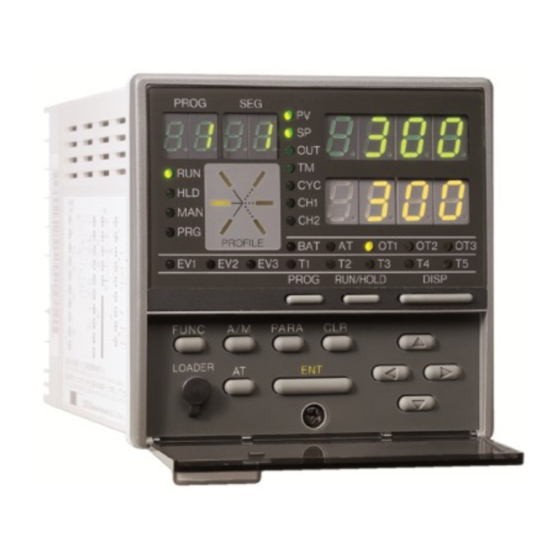
Chapter 2. NAMES & FUNCTIONS OF PARTS Chapter 2. NAMES & FUNCTIONS OF PARTS Structure This controller comprises a body, console, case, standard terminal base and add-on terminal base. Console Contains 7-segment display, LEDs, Case operation keys and loader connector. Body Contains console and electrical circuits. -
Page 20: Console
Chapter 2. NAMES & FUNCTIONS OF PARTS Console The console comprises keys for operating the controller, displays and LEDs. Basic display state The “basic display state” is the state in which the controller operating state is displayed on the console. When the power is turned ON, the controller is in this state. - Page 21 Chapter 2. NAMES & FUNCTIONS OF PARTS • Mode indicator LEDs RUN, HLD : Display the READY, RUN, HOLD, FAST and END modes. (See follow- ing table.) Mode READY HOLD FAST Blinking Blinking : Lights in the MANUAL mode, and goes out in the AUTO mode. : Lights in the program setup state.
-
Page 22: Keys
Chapter 2. NAMES & FUNCTIONS OF PARTS Keys PROG DISP : Program key : Display key FUNC : Function key : Left arrow key, right arrow key : Up arrow key, down arrow key Loader jack : Auto/Manual key RUN/HOLD : Run/Hold key : Auto-tuning key : Clear key... - Page 23 Chapter 2. NAMES & FUNCTIONS OF PARTS Category Function Key operation Starts parameter setup. So the controller enters se- FUNC Parameter setup PARA lection of setup group (major item). (in basic display state) PARA To change the setup group (major item) To fix the setup group To moves between individual items (minor items) To start changing individual item setting values...
- Page 24 Chapter 2. NAMES & FUNCTIONS OF PARTS Category Function Key operation PROG Program copy To start program copy (in basic display state) To change the copy destination program No. To execute program copy (while setting value is blinking) DISP To end program copy DISP General reset FUNC...
-
Page 25: Functions Using Two Or More Keys
Chapter 2. NAMES & FUNCTIONS OF PARTS Functions using two or more keys : Reset keys PROG RUN/HOLD RUN/HOLD PROG Press with held down in the basic display state to reset the controller. The controller enters the READY mode in the RUN, HOLD, FAST or END modes. The controller cannot be reset in the READY mode by key operation. -
Page 26: Input Type And Range No
Chapter 2. NAMES & FUNCTIONS OF PARTS Input Type and Range No. Inputs Thermocouple Input Format Range No. Code Temp. Range ( C) Temp. Range ( F) K (CA) 0 to 1200 0 to 2400 K (CA) 0.0 to 800.0 0 to 1600 K (CA) 0.0 to 400.0... - Page 27 Chapter 2. NAMES & FUNCTIONS OF PARTS dc current, dc voltage Input Format Range No. Code Range (programmable) 4 to 20mA 0 to 20mA 0 to 10mA -10 to +10mV 0 to 100mV -1999 to 9999 0 to 1V -1 to +1V 1 to 5V 0 to 5V 0 to 10V...
-
Page 28: Chapter 3. Mounting
Chapter 3. MOUNTING Chapter 3. MOUNTING External Dimensions Unit: mm (18) 159.5 Mounting bracket 81405411-001 Soft dust-proof cover set (sold separately) 81446087-001 Hard dust-proof cover set (sold separately) 81446083-001 Terminal cover set (sold separately) 81446084-001 Terminal screw 78.4 Back plate Add-on terminal base... -
Page 29: Panel Cutout Dimensions
Chapter 3. MOUNTING Panel Cutout Dimensions Use a steel panel of at least 2mm in thickness for mounting the controller. Unit: mm Panel cutout dimensions Panel cutout dimensions during multiple mounted (recommended) 92 +0.8 96 x (N - 1) 96 x N - 4 N=number of units installed Panel cutout dimensions when mounting units horizontally and vertically (recommended) 99 min. -
Page 30: Mounting
Chapter 3. MOUNTING Mounting WARNING Before wiring, or removing/mounting the DCP301, be sure to turn the power OFF. Failure to do so might cause electric shock. Do not disassemble the DCP301. Doing so might cause electric shock or faulty operation. CAUTION Use the DCP301 within the operating ranges recommended in the specifi- cations (temperature, humidity, voltage, vibration, shock, mounting direc-... -
Page 31: Noise Generating Sources And Countermeasures
Chapter 3. MOUNTING Noise generating sources and countermeasures • Generally, the following generate electrical noise: (1) Relays and contacts (2) Solenoid coils, solenoid valves (3) Power lines (in particular, 90Vac min.) (4) Induction loads (5) Inverters (6) Motor commutators (7) Phase angle control SCR (8) Wireless communications equipment (9) Welding equipment (10) High-voltage ignition equipment... -
Page 32: Mounting Method
Chapter 3. MOUNTING Mounting method Panel Mounting bracket 81405411-001 Mounting bracket • Firmly secure the top and bottom of the controller by the mounting brackets. • When mounting the controller, secure by lower mounting bracket (1) first. Mounting bracket Panel Panel Handling Precautions To secure the controller, tighten the screw on the mounting bracket (supplied) -
Page 33: Chapter 4. Wiring
Chapter 4. WIRING Chapter 4. WIRING Wiring Precautions WARNING Before connecting the DCP301 to the measurement target or external con- trol circuits, make sure that the FG terminal is properly grounded (100 max.). Failure to do so might cause electric shock or fire. Before wiring, or removing/mounting the DCP301, be sure to turn the power OFF. - Page 34 Handling Precautions • Before wiring the DCP301, check the controller catalog No. and terminal Nos. on the label on the rear of the body. After wiring the DCP301, be sure to check the wiring for any mistakes. • Maintain a distance of at least 50cm between I/O leads or communications leads and the power lead.
-
Page 35: Compensating Lead
Chapter 4. WIRING Compensating Lead In the case of thermocouple input, connect the bare thermocouple lead to the terminal. If the thermocouple is located a long way from the DCP301 or the thermocouple is connected to a terminal, extend the connection using a compen- sating lead and then connect to the terminal. -
Page 36: Terminal Connections
Chapter 4. WIRING Terminal Connections Use crimped terminals that fit onto M3.5 screws. Unit: mm 3.7dia. Handling Precautions • When installing the DCP301 in locations subject to vibration or impact, be sure to use round crimped terminals to prevent the lead from coming loose from the terminal. -
Page 37: Layout Of Terminals And Recommended Lead Draw-Out Direction
Chapter 4. WIRING Layout of Terminals and Recommended Lead Draw-out Direction Wiring is carried out on the standard terminal base or add-on terminal base. The following diagram shows the recom- mended draw-out directions for the leads on the standard terminal base. The lead draw-out directions are the same when using the add-on terminal base. -
Page 38: Connecting The Ground And Power Supply
Chapter 4. WIRING Connecting the Ground and Power Supply Power supply Connect the DCP301 to a single-phase power supply for controllers, and take measures to prevent the influence of electrical noise. 200/200V, Recommended 100/100V line filter insulated transformer DCP301 Instrument 81446364-001 power supply Other circuits... -
Page 39: Wiring Of Standard And Add-On Terminal Base
Chapter 4. WIRING Wiring of Standard and Add-on Terminal Base Standard terminal layout 5G output Instrument 6D output power supply External switch input (RSW) OD output 5K output 2G output 3D output Auxiliary output 90 to 264Vac RSW1 50/60Hz RSW2 FG (Frame GND) 4 to 20mA RSW3... -
Page 40: Connecting Inputs (Analog Inputs)
Chapter 4. WIRING Connecting Inputs (analog inputs) Connecting input 1 Multiple input 1 supports various sensor inputs. Connect as follows according to the sensor being used. • Thermocouple input • RTD input • dc voltage input • dc current input V, mV Handling Precautions •... -
Page 41: Connecting Control Outputs (Outputs 1, 2)
Chapter 4. WIRING Connecting control outputs (outputs 1, 2) WARNING Before wiring, or removing/mounting the DCP301, be sure to turn the power OFF. Failure to do so might cause electric shock. Relay output (0D) Connect as follows. Contact rating, resistive load Load 5A (30Vdc/120Vac) 4A (240Vac) -
Page 42: Voltage Output (6D)
Chapter 4. WIRING Voltage output (6D) Connect as follows. 2 to 22mAdc With current adjustment function (setup: C 7 8 ) Handling Precautions Voltage output is reliant on an internal fixed-current circuit. Set the current value in the setup data so that the optimum voltage is obtained matched to the conditions of the SSR in use and load. -
Page 43: Connecting Auxiliary Outputs (Outputs 2, 3)
Chapter 4. WIRING Connecting auxiliary outputs (outputs 2, 3) Optional auxiliary outputs can be added on. WARNING Before wiring, or removing/mounting the DCP301, be sure to turn the power OFF. Failure to do so might cause electric shock. 0D, 5G, 6D auxiliary outputs Auxiliary output 1 Receiver (output 2) -
Page 44: Connecting Event Output (Relay Output)
Chapter 4. WIRING 4-10 Connecting Event Output (relay output) Event outputs EV1 and EV2 are 1a contact, and event output EV3 is 1a1b. Event outputs are connected on the standard terminal base. Standard terminal base Contact rating, resistive load EV1 1a Load 1A (30/250Vdc) Power supply... -
Page 45: Connecting Time Event Output (Open-Collector)
Chapter 4. WIRING 4-11 Connecting Time Event Output (open-collector) Optional time event outputs T1 to T5 (open-collector outputs) can be added on. Time event outputs are connected on the add-on terminal base. Add-on terminal base Load Maximum load current: 70mA/load OFF leakage current: 0.1mA max. -
Page 46: 4-12 Connecting External Switch (Rsw) Input
Chapter 4. WIRING 4-12 Connecting External Switch (RSW) Input The DCP301 is provided with four external switch inputs as standard (eight optional). The optional eight inputs are located on the add-on terminal base. Wire the external switch inputs across the standard and add-on terminal bases. Standard terminal base RSW1 Contact... - Page 47 Chapter 4. WIRING Internal circuit for controller components for connecting external switch inputs Standard terminal base Add-on terminal base 12Vdc 12Vdc 12Vdc 12Vdc External External switch switch input input Internal circuit Internal circuit 4-15...
-
Page 48: 4-13 Connecting For Communications
Chapter 4. WIRING 4-13 Connecting for Communications Some controller models support the RS-485 communications interface. Select the RS-485 communications models by selected the required catalog No. Connect as follows. Handling Precautions The DCP301 operates as a slave station. RS-485 interface Add-on terminal base Handling Precautions •... - Page 49 Chapter 4. WIRING 5-wire system RS-485 mutual connection Terminating resistor Slave station DCP301 Terminating resistor Shielded cable Master station Slave station DCP301 Shielded cable Handling Precautions Be sure to connect SG terminals each others. Failure to do so might cause unstable communications.
- Page 50 Chapter 4. WIRING 3-wire system RS-485 mutual connection Terminating resistor Slave station DCP301 Master station Shielded cable Slave station DCP301 Shielded cable Handling Precautions Be sure to connect SG terminals each others. Failure to do so might cause unstable communications. Shielded cable Slave station DCP301 Terminating resistor...
-
Page 51: 4-14 Isolating Inputs And Outputs
Chapter 4. WIRING 4-14 Isolating Inputs and Outputs The following figures show isolation between inputs and outputs. Solid lines show isolated items, and dotted lines show non-isolated items. Control outputs 0D, 5G, 6D, 3D, 5K Input 1 Output 1 (full multiple-input PV (relay, current, voltage output) supported) Output 2... -
Page 52: Chapter 5. Functions
Chapter 5. FUNCTIONS Chapter 5. FUNCTIONS Data Data types The DCP301 supports the following data types. For further details, see Chapter 7, Parameter Setup and Chapter 8, Program Setup. Data that can be changed even in RUN mode Data Parameters Variable parameters Event configuration data Data (e.g. -
Page 53: Program Patterns
Chapter 5. FUNCTIONS Program Patterns Patterns SP and time comprise the settings for a single segment in a pattern. Up to 30 segments can be linked to create a broken-line whose vertical axis is SP and horizontal axis is time. This system is called the “RAMP-X”... -
Page 54: Events 1 To 3
Chapter 5. FUNCTIONS Events 1 to 3 Events 1 to 3 are event configuration data. These are used after setting the event type, event standby, hysteresis and ON delay time. A total of three event types are available: PV type events, controller status events, and time events. - Page 55 Chapter 5. FUNCTIONS PV reverse Deviation direct Deviation reverse SP+EV SP+EV Absolute value deviation direct Absolute value deviation reverse SP direct SP reverse MV direct MV reverse MFB direct MFB reverse...
- Page 56 Chapter 5. FUNCTIONS Controller status events Controller status events are turned ON and OFF according to the controller mode, alarm status and other statuses. Though the event standby function does not function, the ON delay function does. Event setting values (operating point), hysteresis and event standby are not set. •...
-
Page 57: Time Events 1 To 5
Chapter 5. FUNCTIONS Time events 1 to 5 Either of time events or segment No. events can be selected by the time event type item in the event configuration data setup. Time events The ON and OFF times or only the ON time can Segment be set for each event No. - Page 58 Chapter 5. FUNCTIONS • If the ON time is set to 0 in the case of G.Soak Segment standby, output becomes ON from the G.Soak standby state, and the ON time is started at G.Soak standby Segment 8 time start ON time When 0N = 0, output turns completion of the G.Soak standby time.
-
Page 59: Pid Set Selection
Chapter 5. FUNCTIONS PID set selection • Eight sets of PID parameters, PID1 to PID8, are used for control operation. When the PID set No. is set to each seg- ment by designating the PID set segment, control output is calculated by each of the PID parameters. -
Page 60: Pv Start
Chapter 5. FUNCTIONS PV start SP pattern If PV start is set in the program setup, PV is started by regular RUN operation. The first point where PV matches the SP in the program Current Start point pattern (including bias for both PV and SP) is searched PV value for, and operation is started from that point. -
Page 61: Pattern Link
Chapter 5. FUNCTIONS Pattern link Program No.2 pattern-linked to program No.1 “pattern link” is a function for linking patterns together. The link destination program No. is set by the pattern link item. Program No.1 When the pattern link item is set to 0 (initial setting), patterns are not linked. -
Page 62: Modes
Chapter 5. FUNCTIONS Modes Mode types The following modes are available on the DCP301. Mode Program operation READY AUTO MANUAL AUTO MANUAL HOLD AUTO MANUAL FAST AUTO MANUAL AUTO MANUAL Constant-value operation READY AUTO MANUAL AUTO MANUAL Program operation Operation is carried out according to SP, times, events, etc. set to program patterns No.1 to 19. - Page 63 Chapter 5. FUNCTIONS In this mode, the program is running. MV outputs are active in PID control or ON-OFF control, and events and time events are active. In the program operation mode, program operation progresses according to the elapsed time. However, note that progress of program operation stops in the same way as the HOLD mode when the controller is in the G.Soak (Guarantee Soak) standby state.
-
Page 64: Mode Transition
Chapter 5. FUNCTIONS Mode transition During program operation The solid lines in the following diagram show mode transition operations. The broken lines show end of operation. RESET RESET HOLD END AUTO READY AUTO RUN AUTO HOLD AUTO RESET END MANUAL READY MANUAL RUN MANUAL HOLD MANUAL... -
Page 65: Mode Transition Operations
Chapter 5. FUNCTIONS Mode transition operations The following describes mode transition operations. Though “program end” is not an operation, it is described below as it is a factor in mode transition. This operation involves shifting to the RUN mode from the READY, HOLD or FAST modes. -
Page 66: Mode Transition Limitations
Chapter 5. FUNCTIONS Mode transition limitations Mode transition can be carried out operating the console keys, external switching input and communications. The following table shows which operations are enabled in each of the modes. Operation HOLD RESET ADV * FAST (to RUN mode) (to HOLD mode) (to READY mode) (to FAST mode) -
Page 67: Controller And Programmer
Chapter 5. FUNCTIONS Controller and Programmer On 5G output models (output catalog No. appended with 5G), you can choose between use as a controller or a programmer. Set this in setup data C 1 8. You can also choose between controller or programmer functions even if the DCP301 is used for program operation or constant-value operation. -
Page 68: Input Processing Functions
Chapter 5. FUNCTIONS Input Processing Functions Input processing is carried out in the order shown below. Analog input 1 Setting: Setup data C03 Input range type A/D conversion Wiring resistance compensation (resistance temperature detector) (thermocouple) Cold junction compensation Setting: Setup data C72 (DC current and voltage) Square-root extraction Setting: Setup data C07... -
Page 69: Output Processing Functions
Chapter 5. FUNCTIONS Output Processing Functions Three outputs are provided as output processing functions: control output, SP output and auxiliary output. Control output When the DCP301 is selected for use as a controller, control output is operational. How outputs are processed varies according to the output type supported on the model. 5G output Initialization of PID control Setting: Variable parameters 1 OUT/rpi d... - Page 70 Chapter 5. FUNCTIONS 0D, 6D output Setting: Variable parameters 1 OUT/rpi d Initialization of PID control operation Setting: PID parameters p/ 1 / d/RE PID control operation PID parameters dP/di /dd PID parameters br Setting: Variable parameters OTL Output change limitter Setting: PID parameters OL/OH Output upper/lower limit limitter Setting: Variable parameter DI FF...
- Page 71 Chapter 5. FUNCTIONS 2G output Initialization of PID control operation Setting: Variable parameters 1 OUT/rpi d Setting: PID parameters p/ 1 / d/RE PID control operation PID parameters dP/di /dd PID parameters br Output change limitter Setting: Variable parameters OTL Setting: Variable parameter AT AT operation AT execution...
- Page 72 Chapter 5. FUNCTIONS 3D, 5K outputs Initialization of PID control operation Setting: Variable parameters 1 OUT/rpi d PID control operation Setting: PID parameters p/ 1 / d/RE Output change limitter Setting: Variable parameters OTL Setting: Setup data C 12/C 13 MV at over-range Over-range READY mode...
-
Page 73: Sp Output
Chapter 5. FUNCTIONS SP output When the DCP301 is selected for use as a programmer, control output is operational. On 5G output models, SP output is processed is as follows. Main output types Setting: Setup data C 18 Upper/lower limit scaling Setting: Setup data C 19/C20 Setting: Setup data C 16 MV in READY mode... -
Page 74: Chapter 6. Operation
Chapter 6. OPERATION Chapter 6. OPERATION Turning the Power ON The DCP301 is not equipped with a power switch or protective fuses. If necessary, prepare these externally. When a voltage of 90 to 264Vac is applied across terminals (1) and (2) on the DCP301, display appears for about 10s after which control and other operations are started. -
Page 75: Switching The Basic Display
Chapter 6. OPERATION Switching the Basic Display The “basic display state” of the controller collectively refers to the display state of the program No. display, segment No. display, upper display, lower display, basic indicator LED lamps and event LEDs. DISP Each press of successively switches the basic display state. -
Page 76: Display In Program Operation Mode
Chapter 6. OPERATION Display in program operation mode DISP functions Output Model No. Display 0D, 5G, 6D Display 1 Display 2 Display 5 Display 6 Display 7 Display 1 (repeated) Display 1 Display 2 Display 3 Display 5 Display 6 Display 7 Display 1 (repeated) 3D, 5K... - Page 77 Chapter 6. OPERATION Display 4 Program No. Segment No. Heat-side output (%) Pattern Cool-side output (%) tendency Output states of events 1 to 3, time events 1 to 5 This display is exclusive to heat/cool output models (output catalog No. appended with 3D or 5K).
-
Page 78: Display In Constant-Value Operation Mode
Chapter 6. OPERATION Display 7 Program No. Segment No. Pattern Time tendency Output states of events 1 to 3, time events 1 to 5 The digit to which SP values can be entered blinks in the MANUAL mode when pro- grammer functions are selected. - Page 79 Chapter 6. OPERATION Display 3 Motor valve opening (%) Output state of events 1 to 3 This display is exclusive to 2G output models (output catalog No. appended with 2G). Display 4 Heat-side output (%) Cool-side output (%) Output state of events 1 to 3 This display is exclusive to heat/cool output models (output catalog No.
-
Page 80: Program Selection
Chapter 6. OPERATION Program Selection The program No. can be selected on the console within the range 1 to 19. How to select the program No. When the controller is in the basic display state in the program operation READY mode: Program No.1 PROG •... -
Page 81: External Switch (Rsw) Operations
Chapter 6. OPERATION External Switch (RSW) Operations External switch (RSW) inputs In all, the DCP301 is provided with 12 external switch inputs. Each of these inputs are differentiated by RSW1, RSW2 and so forth to RSW12. On models whose option 2 cata- log No. -
Page 82: Program Selection
Chapter 6. OPERATION Program selection The program can be selected in the program operation READY mode. The table below shows program selection by external switch inputs. Two external switch states are pro- vided for selection of programs 10 to 15. When program selection by external switch inputs is set to “0”, the program can be selected by the console keys and by communica- tion with a personal computer. -
Page 83: Read Timing
Chapter 6. OPERATION Read timing Timing of RSW1 to 7 Inputs RSW1 to RSW7 are read according to the following timing. (1) When input changes state from OFF to ON, the time from the change up to reading is 0.2s max. (2) When input changes state from ON to OFF, the time from the change up to reading is 0.2s max. -
Page 84: Manual Operation And Auto-Tuning
Chapter 6. OPERATION Manual Operation and Auto-tuning Manual operation In the MANUAL mode, controller outputs can be manipulated by on the con- sole. Controller functions When outputs are displayed in the basic display state, only one digit in the output value blinks. - Page 85 Chapter 6. OPERATION • Auto-tuning in all instances involves calculating the downtime and critical sensitivity of the line according to two limit cycles and PID values according to suitable charac- teristic equations for each, and automatically writing these PID values. •...
-
Page 86: Chapter 7. Parameter Setup
Chapter 7. PARAMETER SETUP Chapter 7. PARAMETER SETUP Parameter Setup Parameters can be set up when the DCP301 is in the basic display state. DISP If the DCP301 is not in the basic display state, press to set the controller to the basic display state. Selecting the setting group in the parameter setup Parameter setup is divided into two stages: setting group (major item) and individual item (minor item). -
Page 87: Moving Individual Items In The Parameter Setup
Chapter 7. PARAMETER SETUP Moving individual items in the parameter setup With individual items, item codes are displayed in the upper display and setting values are displayed in the lower display. The program No. display goes out, and the item No. is displayed in the segment No. display. - Page 88 Chapter 7. PARAMETER SETUP • Example of individual item matrix (setup date) C 0 0 C 9 1 C 0 1 C 1 1 C 8 1 C 9 1 C 0 1 C 9 2 C 0 2 C 1 2 C 8 2 C 9 2 C 0 2...
-
Page 89: How To Use
Chapter 7. PARAMETER SETUP PARA How to Use PARA for calling up individual items in frequently changed parameters. How to register functions to keys PARA Up to eight individual items in the parameter setup can be assigned to each key. The assignment item must be registered to use this feature. - Page 90 Chapter 7. PARAMETER SETUP Example PARA PARA Let’s register four individual items to . If you press in the basic display state, the 1st to 4th individual items in the table below are displayed successively. In this ex- ample, let’s change the setting values. PARA Order Item to Call by...
- Page 91 Chapter 7. PARAMETER SETUP DISP DISP Display item by Display item by PARA Basic Display PARA PARA key assign- key assign- State ment item 1 ment item 1 (blinking) (normally lit) PARA PARA Display item by Display item by DISP PARA PARA key assign-...
-
Page 92: Parameter Setup List
Chapter 7. PARAMETER SETUP Parameter Setup List Note “U” and “%FS” used in the “Factory Setting” and “Setting” columns in the table mean the following: The decimal point changes according to the input range type setting. For example, when one digit past the decimal point is allowed, -1999U becomes 199.9, and 9999U becomes 999.9. - Page 93 Chapter 7. PARAMETER SETUP Item Code Item Factory User Setting Setting Setting G 5 .T G.Soak time (CH1) 0.1 to 60.0s C P . 1 1 -1999 to 9999U PID auto-switching [Note] point 1-1 C P . 1 2 C 1 1 200U PID auto-switching When setup data...
- Page 94 Chapter 7. PARAMETER SETUP Item Code Item Factory User Setting Setting Setting M .-C Motor control 0: MFB control (conventional) + estimated position control method selection 1: MFB control (conventional) only 2: Estimated position control only [Note] On models other than 2G output models, “– – – –” is displayed and setting is not possible.
-
Page 95: Description Of Variable Parameter Settings
Chapter 7. PARAMETER SETUP Description of variable parameter settings L O C (key lock) 0: Key lock disabled 1: Display of setup data settings disabled 2: Display of parameter settings and program settings disabled 3: Use of operation keys disabled 4: Display of parameter settings and program settings displayed, and use of operation keys disabled •... - Page 96 Chapter 7. PARAMETER SETUP O T L (MV change limit) The MV is increased or decreased by the same value so that the output change is taken as the limit setting value when the output change (%) after PID operation is greater than this limit setting.
- Page 97 Chapter 7. PARAMETER SETUP S t (smart-tuning method selection) 0: Smart-tuning is disabled. 1: The brake value is fixed to inhibit overshoot. 2: Overshoot is inhibited while automatically reviewing the brake value. • When the control direction is set to reverse action, overshoot is inhibited. When set to direct action, undershoot is inhibited.
- Page 98 Chapter 7. PARAMETER SETUP D I F F • ON-OFF control differential When P is set to 0.0 on both 0D and 6D output models, control is set to ON-OFF control, and operational period at that time is set. Reverse action Direct action Differential Differential...
- Page 99 Chapter 7. PARAMETER SETUP Note 1) On heat/cool models, this sets how the relationship between heat-side output and cool-side output should be processed with respect to the MV resulting from PID operation. Dead zone<0 Dead zone=0 100% 100% Dead zone Control output values Output...
- Page 100 Chapter 7. PARAMETER SETUP D v -L (3-position control deviation lower limit) D v -H (3-position control deviation upper limit) H Y -L (3-position control lower limit hysteresis) H Y -H (3-position control upper limit hysteresis) In 3-position control, control is carried out in the following three states in the RUN, HOLD, FAST and END modes.
- Page 101 Chapter 7. PARAMETER SETUP M .-C (motor control method selection) 0: MFB control (conventional) + estimated position control 1: MFB control (conventional) only 2: Estimated position control only • 0: MFB control (conventional) + estimated position control • When MFB (Motor Feed Back) input is normal, the motor position is controlled by the actually measured MFB.
- Page 102 Chapter 7. PARAMETER SETUP M .-A t (motor valve opening automatic adjustment) 0: Adjustment disabled 1: Adjustment enabled This parameter automatically measures the motor fully closed position, fully open posi- tion, and close-open times. The results of calculation are automatically written to M .-C L, M .-O P and M .-t.
-
Page 103: Event Configuration Data Settings "E V
Chapter 7. PARAMETER SETUP Event configuration data settings “E v” Item Code Item Factory User Setting Setting Setting E T 1 Event 1 type PV type events 0: PV direct 1: PV reverse 2: Deviation direct 3: Deviation reverse 4: Absolute value deviation1 direct 5: Absolute value deviation1 reverse 6: SP direct 7: SP reverse... - Page 104 Chapter 7. PARAMETER SETUP Item Code Item Factory User Setting Setting Setting E T 2 Event 2 type PV type events 0: PV direct 1: PV reverse 2: Deviation direct 3: Deviation reverse 4: Absolute value deviation1 direct 5: Absolute value deviation1 reverse 6: SP direct 7: SP reverse 8: MV direct...
- Page 105 Chapter 7. PARAMETER SETUP Item Code Item Factory User Setting Setting Setting E T 3 Event 3 type PV type events 0: PV direct 1: PV reverse 2: Deviation direct 3: Deviation reverse 4: Absolute value deviation1 direct 5: Absolute value deviation1 reverse 6: SP direct 7: SP reverse 8: MV direct...
- Page 106 Chapter 7. PARAMETER SETUP Item Code Item Factory User Setting Setting Setting Time event type 0: T1 to T5 are all time events. 1: T1 is a segment No. event. T2 to T5 are time events. 2: T1 and T2 are segment No. events. T3 to T5 are time events.
-
Page 107: Description Of Event Configuration Data
Chapter 7. PARAMETER SETUP Description of event configuration data E D 1 (event 1 standby) E D 2 (event 2 standby) E D 3 (event 3 standby) 0: Standby OFF 1: Standby ON • When set to standby ON, event output becomes OFF if the controller is in the standby state even if the condition for turning event output ON is satisfied. -
Page 108: Pid Parameter Settings "P I D
Chapter 7. PARAMETER SETUP PID parameter settings “P I d” Item Code Item Factory User Setting Setting Setting P -1 100.0 : 0.0 to 999.9% (0D, 6D output models) Proportional band (PID set 1) 0.0 enables ON-OFF control. 1 -1 Reset time 0.1 to 999.9% (models other than 0D and 6D output models) - Page 109 Chapter 7. PARAMETER SETUP Item Code Item Factory User Setting Setting Setting P -3 2 P 1 D Proportional band 100.0 • When variable parameter setting is 1 (2 (PID set 3) degrees of freedom PID enabled), the parameter ( 1 -3 Reset time ) ideal for control when SP changes and the param-...
- Page 110 Chapter 7. PARAMETER SETUP Item Code Item Factory User Setting Setting Setting P -5 Proportional band 100.0 (PID set 5) 1 -5 Reset time (PID set 5) D -5 Rate time (PID set 5) O L -5 MV lower limit (PID set 5) O H -5 100.0...
- Page 111 Chapter 7. PARAMETER SETUP Item Code Item Factory User Setting Setting Setting P -7 Proportional band 100.0 (PID set 7) 1 -7 Reset time (PID set 7) D -7 Rate time (PID set 7) O L -7 MV lower limit (PID set 7) O H -7 100.0...
-
Page 112: Setup Data Settings "S E T
Chapter 7. PARAMETER SETUP Setup data settings “S E t” Item Code Item Factory User Setting Setting Setting C 0 1 Control action (CH1) 0: Reverse action (heat) 1: Direct action (cool) [Note] On heat/cool models, “– – – –” is displayed and setting is not possible. - Page 113 Chapter 7. PARAMETER SETUP Item Code Item Factory User Setting Setting Setting C 1 1 PID set auto- 0: OFF (PID set segment designation) switching (CH1) 1: ON [Note] When set to 1, the PID set items in the program are invalid.
- Page 114 Chapter 7. PARAMETER SETUP Item Code Item Factory User Setting Setting Setting C 3 1 Unused – [Note] C 3 2 – Unused “– – – –” is displayed and setting is not possible. C 3 3 – Unused C 3 4 Unused –...
- Page 115 Chapter 7. PARAMETER SETUP Item Code Item Factory User Setting Setting Setting C 5 0 Auxiliary output 2 -1999 to 9999U -199.9 to 999.9% lower limit (4mA) C 5 1 [Note] Auxiliary output 2 1000 lower limit (20mA) When the auxiliary output type is MV or MFB, the unit is %.
- Page 116 Chapter 7. PARAMETER SETUP Item Code Item Factory User Setting Setting Setting C 6 7 Alarm display 0: Display ON 1: Display OFF [Note] Even when set to 1, alarm-related events do not operate. C 6 8 0: Display ON Programming item: 1: Display OFF Events 1 to 3...
- Page 117 Chapter 7. PARAMETER SETUP Item Code Item Factory User Setting Setting Setting C 8 2 Expansion setting 2 0: Expansion disabled 1: Expansion enabled [Note] This setting is for service use only. C 8 3 Unused — [Note] “– – – –” is displayed and setting is not possible. C 8 4 Station address 0 to 127...
-
Page 118: Description Of Setup Data Settings
Chapter 7. PARAMETER SETUP Description of setup data settings C 0 7 (input 1 square root extraction dropout) • Generally, the differential pressure detected by an orifice on a differential pressure type flowmeter, is proportional to the square of the flowrate. For this reason, square root extraction is carried out when uniform signals are required. - Page 119 Chapter 7. PARAMETER SETUP C 6 5 (time display) 0: Remaining segment time 1: Total operation time • This selects the time display in the basic display state in the program operation mode. • When set to 0, in the READY mode, the time setting value of the currently selected segment is displayed.
- Page 120 Chapter 7. PARAMETER SETUP C 7 8 (voltage output 1 adjustment) C 7 q (voltage output 2 adjustment) When driving an SSR by voltage time-proportional output, the output voltage of the controller must be within the input rated voltage (optimum ignition voltage) of the SSR. On the DCP301, a newly developed variable output system is utilized that enables output of the optimum ignition voltage even when driving two or more SSRs.
- Page 121 Chapter 7. PARAMETER SETUP (3) Equivalent circuit when N number of SSRs are connected in series DCP301 SSR 1 SSR' – – SSR N SSR' – Formulas (3) and (4) formulas must be satisfied. (3) formula V x Z + V SSR/MIN (4) formula V SSR'...
- Page 122 Chapter 7. PARAMETER SETUP (5) Example: Using Yamatake Corporation’s PGM : 3 to 6V : 260 : 0.8 to 1.3V • What value should I be set to when connecting one PGM? As shown in the figure on the right, a fixed-current system is used for the voltage output of this controller.
- Page 123 Chapter 7. PARAMETER SETUP C q 1 (Input 1 Zener barrier adjustment) The following adjustment must be made when using a Zener barrier. (1) Turn the DCP301 OFF. When you have finished mounting and wiring the DCP301, short-circuit across A and B on the terminals of the RTD. DCP301 Zener barrier Zener barrier...
- Page 124 Chapter 7. PARAMETER SETUP C 9 3 (CPL communications port selection) • When set to 0, CPL communications from the loader jack is not possible. In this case, CPL communications is possible from the addon terminal under setup C 8 4 and C 8 5 communications conditions if the controller model supports CPL communications.
-
Page 125: Table Data Settings "T B L"
Chapter 7. PARAMETER SETUP Table data settings “T B L” Item Code Item Factory User Setting Setting Setting T -A . 1 -1999 to 9999U Input linearization table approximation A1 [Note] C 0 8 T -A . 2 When setup data setting is 0, “–... -
Page 126: Description Of Table Data Settings
Chapter 7. PARAMETER SETUP Description of table data settings t -A . 1 to t -A . b t -b . 1 to t -b . b • These settings are for the A-axis (input) and B-axis (output) settings of input 1 linear- ization table approximation. -
Page 127: Constant-Value Operation Data Settings "C N S T
Chapter 7. PARAMETER SETUP Constant-value operation data settings “C N S t” Item Code Item Factory User Setting Setting Setting M .O D E 0: Program operation Operation mode 1: Constant-value operation [Note] This setting can be changed only in the READY mode. This setting can be set in the SP1 lower to upper limit C 0 q C 1 0... -
Page 128: Chapter 8. Program Setup
Chapter 8. PROGRAM SETUP Chapter 8. PROGRAM SETUP Program Setup Programs can be set up when the DCP301 is in the basic display state. This is sometimes referred to as “program- ming” in this manual. If the DCP301 is not in the basic display state, press DISP to set the controller to the basic display state. -
Page 129: Mode Transition
Chapter 8. PROGRAM SETUP Selecting the program No. after entering program setup (continued) When you select the program No. by this method, the display changes to segment No.1 and the pattern item on the programming map. This method can be used, for example, to select a program No. to set up a program other than the No. - Page 130 Chapter 8. PROGRAM SETUP Description of mode transition states (see page 8-2.) (1) Program setup is entered. (2) Setup item on programming map is moved. (3) Segment on programming map is moved. (4) Entry of the No.1 setup is started. (5) No.1 setting value incremented/decremented, and blinking digit is moved.
-
Page 131: Programming Map
Chapter 8. PROGRAM SETUP Programming map As shown in the figure below, the programming map is arranged in a matrix with the segment Nos. aligned along the horizontal axis and program setup items arranged along the vertical axis. The area surrounded by thick black lines indicates the items that can be designated by segment No. -
Page 132: Display Details
Chapter 8. PROGRAM SETUP Display details The following figure shows the conventions used for displays in this manual. Program/Segment No. Display Displays program/segment No. currently being set up. Decimal point blinks in program setup state. Basic indicator LED lamps : LED lit Program No. -
Page 133: Setting Up Events 1 To 3 Items
Chapter 8. PROGRAM SETUP Setting up events 1 to 3 items When event type is PV type event (1) In the setting display state, move to the event 1 to 3 items of the segment to be set up on the programming map. (2) If you press , the upper display starts blinking to indicate start of entry to the No.1 setup. - Page 134 Chapter 8. PROGRAM SETUP When event type is time event (1) In the setting display state, move to the event 1 to 3 items of the segment to be set up on the programming map. (2) If you press , the upper display starts blinking to indicate start of entry to the No.1 setup.
-
Page 135: Setting Up Time Events 1 To 5
Chapter 8. PROGRAM SETUP Setting up time events 1 to 5 (1) In the setting display state, move to the event 1 to 5 items of the segment to be set up on the programming map. (2) If you press , the upper display starts blinking to indicate start of entry to the No.1 setup. -
Page 136: Setting Up Pid Set No. Items
Chapter 8. PROGRAM SETUP Setting up PID set No. items (1) In the setting display state, move to the PID set No. items of the segment to be set up on the programming map. (2) If you press , the lower display starts blinking to indicate start of entry to the No.1 setup. -
Page 137: Setting Up G.soak (Guarantee Soak) Items
Chapter 8. PROGRAM SETUP Setting up G.Soak (guarantee soak) items (1) In the setting display state, move to the G.Soak item of the segment to be set up on the programming map. (2) If you press , the lower display starts blinking to indicate start of entry to the No.1 setup. -
Page 138: Setting Up Pv Start Items
Chapter 8. PROGRAM SETUP Setting up PV start items (1) In the setting display state, move to the PV start items on the programming map. (The settings are common to all segments as the PV start items are setting items provided for each program.) (2) If you press , the lower display starts blinking to indicate start of entry to the... -
Page 139: Setting Up Pattern Link Items
Chapter 8. PROGRAM SETUP Setting up pattern link items (1) In the setting display state, move to the pattern link items on the programming map. (The settings are common to all segments as the pattern link items are setting items provided for each program.) (2) If you press , the lower display starts blinking to indicate start of entry to the... -
Page 140: Inserting And Deleting Segments
Chapter 8. PROGRAM SETUP Inserting and deleting segments (1) In the setting display state, move to the pattern item of the segment where the seg- ment is to be inserted or deleted on the programming map. FUNC (2) If you press , the display changes to confirm insertion of the segment, and “I N S .”... -
Page 141: Copying Programs
Chapter 8. PROGRAM SETUP Copying Programs The DCP301 can be set for copying programs in the program operation READY mode in the basic display state. If the DISP DCP301 is not in the basic display state, press Operation (1) Set the DCP301 to the program operation READY mode. Set variable parameter L O C to either of 0, 1 or 3, and variable parameter P R T C to 0. -
Page 142: General Reset
Chapter 8. PROGRAM SETUP General Reset A general reset can be executed when the DCP301 is in the READY AUTO mode in the basic display state. If the DISP DCP301 is not in the basic display state, press A “general reset” involves the following operations: •... -
Page 143: Chapter 9. Troubleshooting
Chapter 9. TROUBLESHOOTING Chapter 9. TROUBLESHOOTING Self-diagnostics and Alarm Code Display Self-diagnostics functions are incorporated into the controller. The table on the following page shows the alarm codes that are displayed as a result of self-diagnostics. Self-diagnostics at power ON PROM error An error in the system program stored to PROM has been detected. -
Page 144: Self-Diagnostics Only When Certain Functions Are Operating
Chapter 9. TROUBLESHOOTING Self-diagnostics only when certain functions are operating MFB (motor feedback) adjustment error This error is detected when MFB automatic adjustment is not going smoothly on 2G output models. The corresponding alarm code is displayed when this error is detected. To clear this alarm, either execute automatic adjustment again or turn the power OFF then back ON again. -
Page 145: Trouble During Key Entry
Chapter 9. TROUBLESHOOTING Trouble during Key Entry The program No. does not change by pressing in basic display state PROG Cause Remedy Program selection by external switch input not Set all external switch inputs RSW8 to 12 OFF. The controller is not in the READY mode. Reset the controller. -
Page 146: Prog + Run/Hold In The Basic
Chapter 9. TROUBLESHOOTING The program is not advanced by pressing in the basic display state PROG DISP Cause Remedy RUN/HOLD The controller is in the READY mode. Press to set the controller to the RUN mode. (The controller can be reset in case of external switch input or communications even in the READY mode.) PROG Press... -
Page 147: In The Basic Display
Chapter 9. TROUBLESHOOTING Auto-tuning (AT) is not canceled by pressing in the basic display state Cause Remedy L O C Key lock is enabled. Set variable parameter setting to 0 to 2. Setting group other than “P A R A” is not displayed by pressing by selecting PARA the setting group in parameter set state... -
Page 148: State
Chapter 9. TROUBLESHOOTING Items cannot be changed by pressing in program setup state Cause Remedy The pattern item has not been set. Set SP and time data. C 6 8 C 7 1 Programming items are set to “display OFF”. All setup data settings are “1”. -
Page 149: Program Deletion Cannot Be Confirmed By Pressing
Chapter 9. TROUBLESHOOTING FUNC Insertion/deletion of segments cannot be confirmed by pressing in pro- gram setup state Cause Remedy P R T C The program setup cannot be changed. Set program parameter setting to 0. Reset the controller. The program being set up is being operated (RUN. -
Page 150: Motor Adjustment Is Impossible
Chapter 9. TROUBLESHOOTING Motor Adjustment is Impossible There are two ways of wiring a motor to the DCP301: wiring for direct motor rotation and wiring for reverse motor rotation. When wired for direct motor rotation, the motor rotates in clockwise (CW ) direction when DCP301 output increases. -
Page 151: Normal Wiring For Direct Motor Rotation
Chapter 9. TROUBLESHOOTING Normal wiring for direct motor rotation Upper Display Lit LEDs Lower Display Motor Action Remarks C A .C L Readout decreases If the motor rotates CCW from 1000 to 500 and when OT2 lights, motor stabilizes. terminals 1 and 2 are C A .O P Readout increases wired for direct rotation. -
Page 152: Replacing The Battery
Batteries are small and are easy to swallow. If a child swallows a battery, consult a physician immediately. Return used batteries to Honeywell sales/service office or your dealer. When disposing of used batteries at the user site, observe local bylaws. -
Page 153: Replacement Procedure
Chapter 9. TROUBLESHOOTING Replacement procedure Handling Precautions • Replace with the lithium battery set (model No.: 81446431-001). The lithium battery set can be ordered from Yamatake Corporation. • When removing or mounting the RAM board or battery connectors, do not use metallic tools. - Page 154 Chapter 9. TROUBLESHOOTING (6) Place the body on its save on a desk or flat surface so that the side on which the battery is installed is facing up. (7) Remove the battery from its gray holder. (8) Remove the RAM board (approx. 3cm x 8cm) with the battery still connected to the board.
- Page 155 Chapter 9. TROUBLESHOOTING (12) Fit the battery into the gray holder so that the battery cable is above the RAM board. Gray holder (13) Insert the body into the case. Do not exert excessive force if the body cannot easily fit into the case. Also, make sure that the boards mounted on the body are not loose or twisted.
-
Page 156: Chapter 10. Specifications
Chapter 10. SPECIFICATIONS Chapter 10. SPECIFICATIONS 10-1 Specifications Item Specification Program Number of programs Number of segments 30 per program Segment setting system RAMP-X system: Set by set points (SP) and time. Segment time 0 to 99h 59min, or 0 to 99min 59s (time unit selectable) Basic time accuracy 0.01% (0.1s delay when segment time setting=0) Events (3) - Page 157 Chapter 10. SPECIFICATIONS Item Specification Input Over-range detection 110%FS min.: Upscaled threshold -10%FS max.: Downscaled (Note that F50 range is not downscaled. Lower readout limit of B18 range is 20 C, 68 F.) Cold junction compensa- 0.5 C (under standard conditions) tion accuracy Influence of surrounding 0.2 C (at 0 to 50 C range)
- Page 158 Chapter 10. SPECIFICATIONS Item Specification Mode Program operation mode READY: Ready to run program (control stop/program No. selectable) RUN: Program run HOLD: Program hold FAST: Program fast-forward END: Program end AUTO: Automatic operation MANUAL: Manual operation (output controlled on console) READY: Ready to run program (control stop) Constant-value operation...
- Page 159 Chapter 10. SPECIFICATIONS Item Specification Auxiliary output Control Type PV, SP, deviation, MV, MFB Scaling Supported Output resolution 1/10000 Output 0D output 1 Relay contact Contact type: 1a1b 3D outputs 1, 2 output Contact rating: 5A (30Vdc, resistive load) 5A (120Vac, resistive load) 4A (240Vdc, resistive load) Allowable contact voltage:250Vac, resistive load 125Vdc, resistive load...
- Page 160 Chapter 10. SPECIFICATIONS Item Specification Event/ Events 1, 2 Relay contact Contact type: Time output Contact rating: 1A (240Vac/30Vdc, resistive load) Event Life: 100,000 operations (at rating) Output Min. switching voltage, current: 10V, 10mA Event 3 Relay contact Contact type: 1a1b output Contact rating:...
- Page 161 Chapter 10. SPECIFICATIONS Item Specification Display characters 11bits/character Char. bit count Format 1 start bit, even parity, 1 stop bit; or 1 start bit, no parity, and 2 stop bits 8bits Data length Isolation All inputs and outputs are completely isolated. RS-485 communications can be performed by connecting to a computer equipped with an RS-485 interface.
-
Page 162: Accessories/Option List
Chapter 10. SPECIFICATIONS Item Specification General Transport/storage Ambient temperature -20 to +70°C range Specifica- conditions tions Ambient humidity range 10 to 95%RH (no condensation) Vibration resistance 0 to 4.90m/s (10 to 60 Hz for 2h each in X, Y and Z direc- tions) Impact resistance 0 to 490m/s... -
Page 163: External Dimensions
Chapter 10. SPECIFICATIONS 10-2 External Dimensions Unit: mm (18) 159.5 78.4 10-8... -
Page 164: Hard Dust-Proof Cover Set
Chapter 10. SPECIFICATIONS Soft dust-proof cover set (sold separately) Unit: mm (transparent silicon rubber) Model No.: 81446087-001 15.5 12.5 Hard dust-proof cover set (sold separately) (transparent polycarbonate) Model No.: 81446083-001 Packing 96.6 Terminal cover set (sold separately) (gray non-flammable, heat-resistant PVC) Can be attached to either of Model No.: 81446084-001 standard or add-on terminal base. -
Page 165: Chapter 11. Calibration
Chapter 11. CALIBRATION This chapter covers the field calibrations procedures for the inputs, outputs and various functions of the DCP301 and DCP302 controller after shipment from the factory. When calibration is made in the field, the original factory data is erased, and so the specified input/output accuracies of the controller cannot be assured. -
Page 166: 11-1 Quick Reference Table For Calibration Items
Chapter 11. CALIBRATION 11-1 Quick Reference Table for Calibration Items DCP301 and DCP302 controllers are numbered using the following format. Format items may require different cal- ibration procedures, as shown in Table 11-1. DCP30 * * * * ES * * * Model number: (1) Basic Model Number (2) Output Number... - Page 167 Chapter 11. CALIBRATION Table 11-2. Item and Sub Item Table for Calibration Item Sub Item Description Upper Display Shows Lower Display Shows 0.0.0.0. AdJS Item change code etc. Key test Display test Digital input test Output test (control) Output test (digital output) 1.0.1.1.
- Page 168 Chapter 11. CALIBRATION FUNC While pressing , press simultaneously. ENTER ENTER & & PROG PROG Function test PV input 0.0.0.0. 1.0.1.1. 0 1 0 0 calibration item A d J S A d J S SETUP SETUP PROG PROG Key test 0 0 0 0 0 Gain No.
- Page 169 Chapter 11. CALIBRATION ENTER & PROG PROG C/J sensor Current item 2.0.2.2. 4.0.4.4. 0 4 0 0 calibration item calibration item A d J S A d J S SETUP SETUP PROG PROG CJ zero input count Current output Current input OUT CH1 0 2 0 1 0 4 0 1...
-
Page 170: 11-2 Calibration Procedures
Chapter 11. CALIBRATION 11-2 Calibration Procedures Enter calibration mode LoC=0 PrtC=0 (1) Release keylock. (PARA (2) Press DISP key to permit ordinary indication condition. Change to READY (RUN and HLD are off) and AUTO (MAN off) modes. The following LEDs will illuminate after the above operations. RUN LED is OFF HLD LED is OFF MAN LED is OFF... -
Page 171: Function Test
Chapter 11. CALIBRATION Function test 0.0.0.0 keys to show ( ) on upper display, then press ENT key. Press , , , or 00-01 Key test ( 00-01 Press PARA key until the PROG/SEG display shows ( When you press each key, the data appears in the upper display (shown in Table 11-3). Table 11-3. - Page 172 Chapter 11. CALIBRATION 00-02 Display test ( Press PARA key until the display test starts. Then, each 7-segment LED, LED indicators and LCD illuminates at every 0.5 sec. This is to check if each LED/LCD illuminates. 00-03 Digital input test ( 00-03 Press PARA key until the PROG/SEG display shows ( When you turn on or off each remote switch, the upper display will show the data...
- Page 173 Chapter 11. CALIBRATION 00-04 Digital output test for control output ( 00-04 Press PARA key until the PROG/SEG display shows ( keys, the state of voltage When the digit of upper display is changed by , , , or pulse or relay control output is changed as shown in Table 11-5. Since the 6D hardware is of voltage pulse output (0D and 2G hardware is of relay) spec- ification, the ON/OFF check must be performed in meeting with the specification.
-
Page 174: Pv Calibration
Chapter 11. CALIBRATION PV calibration 1.0.1.1. keys to show ( ) on upper display, then press ENT Scroll , , , or key. Gain No. select Press PARA key until the PROG/SEG display shows (01-01). Connect calibration device (See Section “11-3 Set Up”). Input the gain number (See Table 11-9 and Table 11-10) by scrolling , , , or keys the upper display ( ENT key not required). - Page 175 Chapter 11. CALIBRATION Table 11-11. Range Table of CH1 TC Range Table of CH1 RTD Group Type Code Range No. Gain No. Group Type Code Range No. Gain No. K (CA) K (CA) K (CA) K (CA) JIS ’89 Pt100 (IEC Pt100 ) K (CA) K (CA)
-
Page 176: Cold Junction Sensor Calibration
Chapter 11. CALIBRATION Cold junction sensor calibration 2.0.2.2. keys to show ( ) on upper display, then press ENT Scroll , , , or key. The cold junction input 0% 02-01 (1) Press SETUP key until the PROG/SEG display shows ( (2) Press ENT key after display stabilizes, AD count is shown on lower display. - Page 177 Chapter 11. CALIBRATION 11-3 Set Up 34 33 28 29 34 33 30 29 28 Copper Copper leads leads Millivolt sources Millivolt sources Decade resistance box Decade resistance box Gain No. 0 to 7 Gain No. 16 to 17 Gain No. 9 to 10 Gain No.
- Page 178 Chapter 11. CALIBRATION 11 12 14 15 17 18 Copper leads Digital ammeter Figure 11-11. Current Outputs 11-14...
- Page 180 EN2I-6026 SAFETY REQUIREMENTS To reduce risk of electric shock which could cause personal injury, all safety notices in this documentation. This symbol warns the user of a potential shock hazard where hazardous live voltages may be accessible. If the equipment is used in a manner not specified by the manufacturer, the protection provided by the equipment must be impaired.
- Page 181 Index 2 degrees of freedom PID selection 7-12 Position-proportional output (2G) • • • • • • • • • • • • • 3-position control deviation lower limit 7-15 Relay output (0D) • • • • • • • • • 3-position control deviation upper limit 7-15 Voltage output (6D)
- Page 182 Ground • • • • • • • • • • • • • • • • • • • • • • • • • • • • • • • • • • • • • • • • ON-OFF control differential 7-13 •...
- Page 183 Segment No. display • • • • • • • • • • • • • • • • • • • • • • • • • • • Segment deletion 8-13 • • • • • • • • • • • • • • • • • • • • • • • • • • • • • Segment insertion 8-13 •...
-
Page 184: Revision History
Revision History Printed Manual Number Edition Revised pages Description Date 99-04 EN1I-6197 1st Edition 00-06 2nd Edition iv Instruction Manual.was changed to User's Manual SERVICE CENTERS Address of JAPAN was changed 00-08 3rd Edition 7-32 No. 84 and No. 85 Items was changed 11-10 PV Input 100% of Gain No. - Page 185 HONEYWELL SERVICE CENTERS NETHERLANDS NORWAY HONEYWELL BV HONEYWELL A/S Laaderhoogtweg 18 Askerveien 61 NL-1101 EA AMSTERDAM ZO PO Box 263 THE NETHERLANDS N-1371 ASKER Tel.:31 20 56 56 911 NORWAY Tel.:47 66 90 20 30 POLAND PORTUGAL HONEYWELL Ltd UI Augustowka 3...
- Page 186 A1020 VIENNA Tel.:61 2 353 7000 AUSTRIA BELGIUM Tel.:43 1 213 300 HONEYWELL S.A. BRAZIL Avenue de Schipol, 3 HONEYWELL DO BRAZIL AND CIA 1140 BRUSSELS Rua Jose Alves Da Chunha BELGIUM Lima 172 Tel.:32 2 728 27 11 BUTANTA CANADA...
- Page 187 No. CP-UM-5093E...
Need help?
Do you have a question about the DCP301 and is the answer not in the manual?
Questions and answers