Honeywell DC1000 Series Product Manual
Digital controller
Hide thumbs
Also See for DC1000 Series:
- Product manual (32 pages) ,
- Program configuration manual (3 pages) ,
- Product manual (64 pages)

Related Manuals for Honeywell DC1000 Series


Summary of Contents for Honeywell DC1000 Series
- Page 1 DC1000 Series Digital Controller Product Manual 51-52-25-113 August 2005 www.DataSheet4U.net Industrial Measurement and Control...
- Page 2 Contact your local sales office for warranty information. If warranted goods are returned to Honeywell during the period of coverage, Honeywell will repair or replace without charge those items it finds defective. The foregoing is Buyer's sole remedy and is in lieu of all other warranties, expressed or implied, including those of merchantability and fitness for a particular purpose.
- Page 3 This document provides descriptions and procedures for the Installation, Configuration, and Operation of your DC1000 Controller. Contacts World Wide Web The following lists Honeywell’s World Wide Web sites that will be of interest to our customers. Honeywell Organization WWW Address (URL) Corporate http://www.honeywell.com...
- Page 4 Introduction Symbol Definitions The following table lists those symbols used in this document to denote certain conditions. Symbol Definition This CAUTION symbol on the equipment refers the user to the Product Manual for additional information. This symbol appears next to required information in the manual. WARNING PERSONAL INJURY: Risk of electrical shock.
-
Page 5: Table Of Contents
Introduction Contents INTRODUCTION ....................1 Overview............................1 INSTALLATION..................... 3 Overview............................3 Condensed Specifications .......................4 Model Number Interpretation ......................6 Mounting............................8 2.4.1 Physical Considerations .......................8 2.4.2 Overall Dimensions......................8 2.4.3 Mounting Procedure......................10 Wiring ............................11 2.5.1 Electrical Considerations ....................11 Wiring Diagrams...........................12 2.6.1 Identify Your Wiring Requirements ..................12 2.6.2 Making Terminal Connections...................12 2.6.3... - Page 6 Introduction 4.3.5 System Alarm........................33 Function Lock ..........................34 Parameter Display Set (Hide or Display)..................35 4.5.1 Overview..........................35 4.5.2 Functions of SETs......................35 Input Codes ...........................37 4.6.1 Code Selection ........................37 PROGRAMMER (OPTIONAL) ................41 Overview............................41 5.1.1 Introduction........................41 Programmer Terminologies ......................41 Operating Key Functions ......................41 Program Functions ........................41 5.4.1 Program Running Alarm ....................41...
- Page 7 Introduction Tables Table 2-1 Condensed Specifications _____________________________________________________ 4 Table 3-1 Displays, LEDs, and Keys ____________________________________________________ 18 Table 3-2 Mode Change Instructions ____________________________________________________ 19 Table 3-3 Operation Mode Prompts _____________________________________________________ 20 Table 4-1 Configuration 1 Mode________________________________________________________ 24 Table 4-2 Configuration 2 Mode________________________________________________________ 26 Table 4-3 Alarm Function Selections ____________________________________________________ 29 Table 4-4 Functions of Sets____________________________________________________________ 35 Table 4-5 Thermocouple Inputs ________________________________________________________ 37...
- Page 8 Introduction Figures Figure 2-1 Model DC1010 Dimensions ___________________________________________________ 8 Figure 2-2 Model DC1020 Dimensions ___________________________________________________ 8 Figure 2-3 Model DC1030 Dimensions ___________________________________________________ 9 Figure 2-4 Model DC1040 Dimensions ___________________________________________________ 9 Figure 2-5 Mounting Procedure ________________________________________________________ 10 Figure 2-6 Model DC1010 Wiring ______________________________________________________ 13 Figure 2-7 Model DC1020, DC1025 Wiring ______________________________________________ 14 Figure 2-8 Model DC1030 Wiring ______________________________________________________ 15 Figure 2-9 Model DC1040 Wiring ______________________________________________________ 16...
-
Page 9: Introduction
Parameters can also be hidden to the user to prevent unauthorized configuration of the unit. Various Control Algorithms The DC1000 series of controllers provides several different algorithms: • PID or ON/OFF Control • Hear/Cool Algorithms with 2 different PID sets •... - Page 10 Introduction CE Conformity (Europe) This product is in conformity with the protection requirements of the following: European Council Directive; 73/23/EEC - the Low Voltage Directive, and 89/336/EEC - the EMC Directive. Conformity of this product with any other “CE Mark” Directive(s) shall not be assumed.
-
Page 11: Installation
Installation 2 Installation 2.1 Overview Introduction Installation of the DC1000 consists of mounting and wiring the controller according to the instructions given in this section. Read the pre-installation information, check the model number interpretation (Subsection 2.3), and become familiar with your model selections, then proceed with installation. -
Page 12: Condensed Specifications
Installation 2.2 Condensed Specifications Honeywell recommends that you review and adhere to the operating limits listed in Table 2-1 when you install your controller. Table 2-1 Condensed Specifications TECHNICAL DATA TC (K, J, R, S, B, E, N, T, W, PL II, U, L) Type of Input RTD (Pt100Ω, JPt100Ω, JPt50Ω) - Page 13 Installation INPUT ACTUATIONS 0.0~200.0, 400.0, 600, 800, 1000, 1200 °C 0.0~200.0, 400.0, 600, 800, 1000, 1200 °C 0.0~1600, 1769 °C 0.0~1600, 1769 °C 0.0~1820 °C 0.0~800, 1000 °C 0.0~1200,1300 °C 0.0~400.0, 200.0 °C, 0.0~350.0 °C 0.0~2000, 2320 °C 0.0~1300, 1390 °C PL II -199.9~600.0, 200.0 °C, 0.0~400.0 °C 0.0~400.0, 800.0 °C...
-
Page 14: Model Number Interpretation
Installation 2.3 Model Number Interpretation Introduction Write your controller’s model number in the spaces provided below and circle the corresponding items in each table. This information will also be useful when you wire your controller. Instructions Select the desired Key Number. The arrow to the right marks the selections available. Make one selection each from Tables I through III using the column below the proper arrow. - Page 15 Installation Availability DC10_ _ _ _ 10 20 30 40 Table II Selection Transmitter None 0 _ _ 4-20 mA 1 _ _ 0-20 mA 2 _ _ 0-5 V A _ _ 0-10 V B _ _ 1-5 V C _ _ 2-10 V D _ _...
-
Page 16: Mounting
Installation 2.4 Mounting 2.4.1 Physical Considerations The controller can be mounted on either a vertical or tilted panel using the mounting bracket supplied. Adequate access space must be available at the back of the panel for installation and servicing activities. •... -
Page 17: Figure 2-3 Model Dc1030 Dimensions
Installation Figure 2-3 Model DC1030 Dimensions Figure 2-4 Model DC1040 Dimensions 8/05 DC1010/1020/1030/1040 Product Manual... -
Page 18: Mounting Procedure
Installation 2.4.3 Mounting Procedure Before mounting the controller, refer to the nameplate on the outside of the case and make a note of the model number. It will help later when selecting the proper wiring configuration. 1. Put the mounting bracket in the rail on the top &... -
Page 19: Wiring
Installation 2.5 Wiring 2.5.1 Electrical Considerations Precautions The controller is considered “rack and panel mounted equipment” per EN61010-1, Safety Requirements for Electrical Equipment for Measurement, Control, and Laboratory Use, Part 1: General Requirements. Conformity with 72/23/EEC, the Low Voltage Directive requires the user to provide adequate protection against a shock hazard, The user shall install this controller in an enclosure that prevents the OPERATOR access to the rear terminals. -
Page 20: Wiring Diagrams
Installation 2.6 Wiring Diagrams 2.6.1 Identify Your Wiring Requirements To determine the appropriate diagrams for wiring your controller, refer to the model number interpretation in this section. The model number of the controller is on the outside of the case. Shielded twisted pair cable are required for all Analog I/O, Process Variable, RTD, Thermocouple, dc millivolt, low level signal, mA, Digital Output, and computer interface circuits. -
Page 21: Wiring Diagrams
Installation 2.6.3 Wiring Diagrams Noise POWER Filter AC 100 ~ 240V (50 / 60Hz) DC 15 ~ 50V (option) OUTPUT O U T2 O U T1=5 i near Vol t Li near Rel ay A, B, C , D O U T1 Rel ay Vol t Li near ALARM A, B, C , D... -
Page 22: Figure 2-7 Model Dc1020, Dc1025 Wiring
Installation Noise POWER Filter AC 100 ~ 240V (50 / 60Hz) DC 15 ~ 50V (option) OUTPUT i near OUT2 R el ay Vol t Li near A, B , C , D OUT1 R el ay Vol t Li near ALARM AUX. -
Page 23: Figure 2-8 Model Dc1030 Wiring
Installation Noise POWER Filter AC 100 ~ 240V (50 / 60Hz) DC 15 ~ 50V (option) OUTPUT i near O U T2 O U T1=5 Rel ay Vol t Li near A, B, C , D O U T1 Rel ay Vol t Li near PRO T ALARM AUX. -
Page 24: Figure 2-9 Model Dc1040 Wiring
Installation COMM. Noise POWER COMM COMM Filter RS232 RS485 AC 100 ~ 240V (50 / 60Hz) DC 15 ~ 50V (option) AUX. OUT OUTPUT INPUT OUT2 OUT1=6 OUT1=5 inear Relay Volt Linear A,B,C,D OUT1 Relay Volt Linear PROT ALARM OUT1=9 PROT A,B,C,D OUT1=8... -
Page 25: Operation
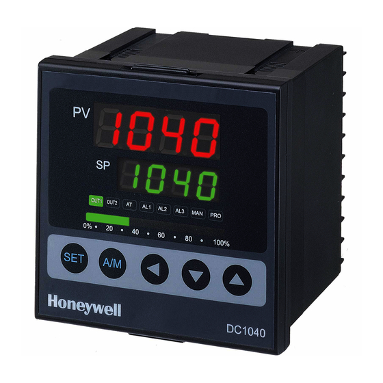
Operation 3 Operation 3.1 Overview This section gives you all the information necessary to help you monitor and operate your controller including an Operator Interface overview, an explanation of the Displays, keys, and LEDs, and Mode access, and Operation Modes. 3.2 Operator Interface Overview Figure 3-1 is a view of the operator interface. -
Page 26: Displays, Leds, And Keys
Operation 3.2.1 Displays, LEDs, and Keys Table 3-1 Displays, LEDs, and Keys Displays Upper Display 4 digits dedicated to display the PV. In configuration mode, this display indicates the name of a parameter. Lower Display 4 digits dedicated to display the SP. In configuration mode, this display indicates the value of a parameter or the status of the parameter selected Bargraph A 10 green LEDs’... -
Page 27: Mode Access
Operation 3.3 Mode Access Operation Operation Configuration 1 Configuration 1 Program Program Configuration 2 Configuration 2 Set Up Set Up Figure 3-2 Mode Access Diagram 3.3.1 How to move from one mode to another Refer to Figure 3-2 and Table 3-2 for instructions. Table 3-2 Mode Change Instructions Step Action... -
Page 28: Operation Mode
Operation 3.4 Operation Mode 3.4.1 Key Functions 3.4.1.1 Changing Parameter Value Press the SHIFT KEY to change the parameters. If the SHIFT KEY is pressed, the first digit begins blinking. Press the UP KEY or DOWN KEY to increase or decrease the value of this digit, and then press the SHIFT KEY again to go to the next digit. -
Page 29: Control Types
Operation 3.4.3 Control Types 3.4.3.1 Manual Operation In the manual mode, the operator directly controls the controller output level. Press the “A/M”key until you see “OUTL” in the upper display and a fixed control output value in the lower display. To change the value of the Output (%), refer to Paragraph 3.4.1.1 Changing Parameter Value. -
Page 30: Set Point
Operation Example : SV=200ºC, ATVL=5, Auto tuning point is at 195ºC During auto tuning the PV value will oscillate around 195ºC. Hence the PV will not go over 200ºC. Note: In programmable model, ATVL means Auto-tuning point Auto tuning failure Possible cause 1: ATVL is too big. -
Page 31: Alarm Functions And Associated Prompts
Operation 3.4.5 Alarm Functions and Associated Prompts Make sure each alarm is set properly. • See “Configuration 2” Mode (Table 4-2). Set the required Alarm Code in prompts “Ald1”, “Ald2”, and “Ald3”. Alarm Code: 00 to 19 (Table 4-3 Alarm Function Selections) •... -
Page 32: Configuration
Configuration 4 Configuration 4.1 Introduction Configuration is a dedicated operation where you use straightforward keystroke sequences to select and establish (configure) pertinent control data best suited for your application. To assist you in the configuration process, there are prompts that appear in the upper and lower displays. - Page 33 Configuration Displays Parameter Description Default Value Shown Main Control (OUT 1) Output Type (SSR → 1, 4-20mA → 0, Relay → 10) Cycle of Control Output Range: 0 to 150 seconds Main Control (OUT 1) For On/Off Control (P1=0) (Range 0-1000) Actuation of Hysteresis ON: PV<= (SP –...
-
Page 34: Table 4-2 Configuration 2 Mode
Configuration 4.2.1 Configuration 2 To access ‘Configuration 2’ mode, press the ‘ SHIFT ’ key for 5 seconds WHILE pressing ‘SET’ key FIRST when in ‘Operation’ or ‘Configuration 1’ mode. Table 4-2 Configuration 2 Mode Displays Parameter Description Default Value shown except for examples Input 1 (INP1) - Page 35 Configuration Displays Parameter Description Default Value shown except for examples Time set for Alarm 2 * Range: 0-99 min, 59 seconds 0= flickering alarm, 99:59= continual alarm Other = Time delay for alarm Alarm Code for Alarm 3 * Refer to Table 4-3 for Alarm Codes. Time set for Alarm 3 * Range: 0-99 min, 59 seconds 0= flickering alarm, 99:59= continual alarm...
- Page 36 Configuration Displays Parameter Description Default Value shown except for examples Wait Function To set “WAIT” for program operation Extra Set DO NOT change the value of this parameter ID Number Communication ID Number Baud Rate DO NOT change the value of this parameter SP Compensation Range: -1000 to 1000 PV Compensation...
-
Page 37: Alarms Configuration
Configuration 4.3 ALARMS CONFIGURATION 4.3.1 Alarm Function Selections These Alarm Function Selections are entered in “Configuration 2”. See Section 4.2.1. Table 4-3 Alarm Function Selections Code Description Hold-ON Refer to 00 / 10 None Deviation high alarm Figure 4-2 Deviation high alarm Figure 4-3 Deviation low alarm Figure 4-4... -
Page 38: Deviation Alarm Overview
Configuration 4.3.2 Deviation Alarm Overview The Alarm SP (Set Point) is to be changed as the SP moves. In this case, the Alarm SP preserves a certain deviation value with the SP. When an alarm is set, a certain deviation value with the preset SP should be defined. -
Page 39: Figure 4-4 Lower Limit Deviation Alarm
Configuration Figure 4-4 Lower Limit Deviation Alarm (Alarm Code 02, Alarm release in the first alarming situation) Figure 4-5 Lower Limit Deviation Alarm (Alarm Code 12, No alarm release in the first alarming situation) Figure 4-6 Dev. Band Breakaway Alarm [Hold On = Yes] (Alarm Code 03, Alarm release in the first alarming situation) Figure 4-7 Dev. -
Page 40: Absolute Value Alarm Overview
Configuration 4.3.3 Absolute Value Alarm Overview The Alarm SP (Set Point) is to be fixed even though the SP moves. When an alarm is set, the absolute value of the Alarm SP should be defined. Alarm Set Point (Fixed) Figure 4-10 Absolute Value Alarm 4.3.3.1 Types of Absolute Value Alarms Figure 4-11 Absolute Upper Limit Alarm [Hold On = Yes]... -
Page 41: Program Alarm
Configuration 4.3.4 Program Alarm 4.3.4.1 Segment End Alarm (Alarm Code 07) Once the selected segment is completed, the alarm becomes activated - ALD1 – ALD3 Set the Alarm Code 07 - AL1 – AL3 Enter Segment No.for alarms - ALT1 – ALT3 Define the alarm timing (0= Flickering, 99.59 = Continuous, Others = Time Delay*) * If ALD1-ALD3 is "07"... -
Page 42: Function Lock
Configuration 4.4 Function Lock According to the status of the parameter “LCK” in ‘Configuration 1’ mode, ‘access to modes’ and ‘change of values’ can be prohibited. LCK=0000 MODE ACCESS-Access to ‘Operation’, Configuration1 & 2’ modes allowed (* Default) LCK=0100 MODE ACCESS-Access to ‘Operation’ & ‘Configuration 1’ mode allowed VALUE CHANGE-Every value change in each mode allowed LCK=0110... -
Page 43: Parameter Display Set (Hide Or Display)
Configuration 4.5 Parameter Display Set (Hide or Display) 4.5.1 Overview You can choose to hide or display some parameters by selecting the set mode of each. See Figure 4-18 Display Status for an interpretation of the Status of the Sets. Refer to Table 4-4 for Functions of the Sets. - Page 44 Configuration Function Remarks Number 0 = Not repeat 1 = Program repeat Programmer Model Only 0 = No power failure option See Section 5. 1 = With power failure option 0 = Program starts at 0 (Note 1) 1 = Program starts from PV DO NOT USE SET 8.4.
-
Page 45: Input Codes
Configuration 4.6 Input Codes 4.6.1 Code Selection It requires that the Input Code in ‘Configuration 2’ mode be selected properly before the operation starts. See Section 4.2.1 [Parameters Input 1 (INP1) and Input 2 (INP2)] Table 4-5 Thermocouple Inputs TYPE CODE RANGE 0.0~200.0°C... -
Page 46: Table 4-6 Rtd Inputs
Configuration TYPE CODE RANGE -199.9~200.0°C -199.9~392.0°F 0.0~400.0°C 0.0~752.0°F 0~400°C 0~752°F 0~800°C 0~1472°F Table 4-6 RTD Inputs TYPE CODE RANGE -199.9~600.0°C -199.9~999.9°F -199.9~400.0°C -199.9~752.0°F -199.9~200.0°C -199.9~392.0°F Pt100 0~200°C 0~392°F 0~400°C 0~752°F 0~600°C 0~1112°F -199.9~600.0°C -199.9~999.9°F -199.9~400.0°C -199.9~752.0°F -199.9~200.0°C -199.9~392.0°F Pt100 0~200°C 0~392°F 0~400°C 0~752°F... -
Page 47: Table 4-7 Linear Inputs
Configuration Table 4-7 Linear Inputs CODE SIGNAL INPUT TYPE RANGE 0-20mA, 0-1V, 0-5V, 0- 0 - 50mV -1999~9999 10 - 50mV 4-20mA, 1-5V, 2-10V -1999~9999 *The default of Input Code is ‘AN5’ (4-20mA) for the model of linear input type. (DC10X0X L -XXX-XXX-X) * DO NOT change the input type without technical assistance because it requires some hardware changes on the input board in order to select a certain linear input type. - Page 48 Configuration DC1010/1020/1030/1040 Product Manual 8/05...
-
Page 49: Programmer (Optional)
Programmer (Optional) 5 Programmer (Optional) 5.1 Overview 5.1.1 Introduction The program function of DC1000 has 2 program patterns, and each program has Max. 8 segments. The programs can be linked for a continuous 16 segments. The term “programming” is used here to identify the process for selecting and entering the individual ramp and soak segment data needed to generate the required setpoint versus time profile (also called a program). -
Page 50: Segment Completion Alarm
Programmer (Optional) Alarm Operation: During the program running, Alarm 1 will become actuated 5.4.2 Segment Completion Alarm ALD1 (Alarm Code for Alarm 1)= 07 (Segment End Alarm) AL1 (Alarm Condition)= 2 (‘2’ means Segment No.) When segment 2 ends, AL1 will act. -
Page 51: Other Functions
Programmer (Optional) 5.4 Program Functions (continued) 5.4.6 Other Functions These other functions [Program Repeat, Power Failure Option, and Program Start from PV] are set through the SETS function (Refer to Table 4-4 Functions of Sets). Table 5-2 Associated Program Functions Function Remarks 0 = No Program Repeat... -
Page 52: Program Configuration Prompts
Programmer (Optional) Program Configuration Prompts 5.5.1 Overview The prompts to configure the programs will appear after the operation mode prompts. See Table 3-3. Also see Table 5-2 for Associated program functions. 5.5.2 Configuration Table 5-3 Program Configuration Prompts Displays Parameter Description Start from Operation Mode –... - Page 53 Programmer (Optional) Displays Parameter Description Setpoint for Segment 2 Range: LSPL (Lower Setpoint Limit) to USPL (Upper Setpoint Limit) See Table 4-2 for Limit settings Time Setting for Segment 2 Range: 0-99 hrs:59 minutes Ramp segment* = Changing Setpoint time Soak segment** = Fixed Setpoint time Output Limit for Segment 2 Range: 0 to 100%...
- Page 54 Programmer (Optional) Displays Parameter Description Output Limit for Segment 5 Range: 0 to 100% If OUT = 0, program will end Setpoint for Segment 6 Range: LSPL (Lower Setpoint Limit) to USPL (Upper Setpoint Limit) See Table 4-2 for Limit settings Time Setting for Segment 6 Range: 0-99 hrs:59 minutes Ramp segment* = Changing Setpoint time...
-
Page 55: Program Example
Programmer (Optional) 5.5.3 Program Example Profile Segment Setpoint Time Settings Number Values SP 1 = 20 T 1 = 00:01 SP 2 = 50 T 2 = 09:00 SP 3 = 50 T 3 = 00:02 SP 4 = 90 T 4 = 00:02 SP 5 = 90 T 5 = 00:02... -
Page 56: Error Codes
Error Codes 6 Error Codes Overview Introduction Instrument performance can be adversely affected by installation and application problems as well as by hardware problems. We recommend that you investigate the problems in the following order: Table 6-1 Error Codes ERROR CODE DESCRIPTION SOLUTION Open the circuit of ‘INPUT 1’... -
Page 57: Index
7 Index Hysteresis .............. 25 Absolute Value Alarm Overview ......32 Hysteresis for alarms ..........27 Alarm 1..............20 Alarm 2..............20 Input 1..............26 Alarm 3..............20 Input 2..............26 Alarm Code for Alarm 1........26 Input Codes............37 Alarm Code for Alarm 2........ - Page 58 Parameter Display Set (Hide or Display) ....35 Segment Completion Alarm ........42 Physical Considerations........... 8 Segment End Alarm..........33 PID Control ............21 Set Point ..............22 Power Failure Option ..........43 Setpoint for Segment ..........44 Pre-installation Information........3 Setpoint Limit............
- Page 60 Industrial Measurement and Control Honeywell Korea 191 HanGangRo 2ga, YongSanGu Seoul, Korea 51-52-25-113 Rev. 1 0805 Printed in Korea...
Need help?
Do you have a question about the DC1000 Series and is the answer not in the manual?
Questions and answers