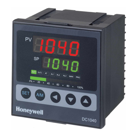
Honeywell DC1010 Instruction Manual
Hide thumbs
Also See for DC1010:
- Product manual (29 pages) ,
- Wiring diagram (4 pages) ,
- Product manual (60 pages)
Table of Contents
Advertisement
Advertisement
Table of Contents

Related Manuals for Honeywell DC1010


Summary of Contents for Honeywell DC1010
- Page 1 Instruction Manual (Input Conversion) DC1010/1020 1030/1040 Rev 4...
-
Page 2: Table Of Contents
Contents 1. Input Change (TC & Linear RTD) ..................3 2. Wiring Distinction between TC& Linear ..................4 3. Linear Input H/W Setting ......................5 4. To view the ANL1, ANH1 parameters..................7 4-1. Unlock the protection.....................7 4-2. Show the parameters.....................7 4-3. Calibration ........................8 4-4. -
Page 3: Input Change (Tc & Linear Rtd)
To change the input type from TC to RTD or RTD to TC,Move a jumper. For Linear type, it’s same as that of TC. 1) DC1010 2) DC1020/DC1030/1040 * No Calibration or Adjustment Required While Input Conversion between TC & RTD. -
Page 4: Wiring Distinction Between Tc& Linear
2. Wiring Distinction between TC& Linear 1) DC1010 Input Wiring Linear Set Input Code in Level 3 for TC or Linear Input after Profer Wiring 2) DC1030 Input Wiring Linear Set Input Code in Level 3 for TC or Linear Input after Profer Wiring... -
Page 5: Linear Input H/W Setting
3. Linear Input H/W Setting For jumper, please see ‘1. Input Changes’ section. 1) DC1010 Input Code S1 to S5 Input Type R1 to R5 AN 4 AN 5 Jumper Status 0~20 mA R3 = 100 R5 = 2.4 ... - Page 6 3) DC1020/1040 Input Code S1 to S5 Input Type R1 to R5 AN 4 AN 5 Jumper Status 0~20 mA R3 = 100 R5 = 2.4 S3 & S5 Short 4~20 mA 0~1 V R1 = 2 K S1 &...
-
Page 7: To View The Anl1, Anh1 Parameters
4. Calibration Procedure Check if it shows the ANL1 and ANH1 on CONFIGURATION2. (Go to step 4-3.) If the parameters are not shown, go to below steps. 4-1. Unlock the protection Go to ‘LCK’ parameter on CONFIGURATION 1. (1-1) Press the SET key for 5 seconds. It will show P1 on CONFIGURATION 1. 5seconds 5seconds Step (1-4) - Page 8 In case of RSP(Input2), SET2.4=1.(It shows ANL2, ANH2.) (2-3) Press the SET and shift key for 5 seconds and return to OPERATION. 4-3. How to Calibrate (3-1) Preparation of sources - DC Current source : DC 0~20mA or 4~20mA - DC voltage source : DC 0~1V, 0~5V, 0~10V, 1~5V, 2~10V (3-2) Press the SET and shift key for 5 seconds, it will show ‘INP1’...
-
Page 9: Procedure Of Calibration
4-4. Procedure of Calibration (Range of PV : 0~3000, Input : 4~20mA) Set INP1(Level 3), 4~20mA : AN5 Set ‘INP1 = AN5’ (Refer to ‘3. Linear Input H/W Setting’) In case of Linear input model, ‘SET 2.2 = 1’ The default is ‘SET2.2 = 1’ (To activate the steps of ANL1 &...
Need help?
Do you have a question about the DC1010 and is the answer not in the manual?
Questions and answers