Honeywell DC1000 SERIES Product Manual
Digital controller
Hide thumbs
Also See for DC1000 SERIES:
- Product manual (60 pages) ,
- Program configuration manual (3 pages) ,
- Product manual (64 pages)
Table of Contents
Advertisement
Quick Links
Advertisement
Table of Contents

Related Manuals for Honeywell DC1000 SERIES


Summary of Contents for Honeywell DC1000 SERIES
- Page 1 DC1000 SERIES DIGITAL CONTROLLER PRODUCT MANUAL Industrial Measurement & Control...
- Page 2 51-52-25-113 Issue1 March 2004 DC1010/1020/1030/1040 Product Manual...
- Page 3 Contact your local sales office for warranty information. If warranted goods are returned to Honeywell during the period of coverage, Honeywell will repair or replace without charge those items it finds defective. The foregoing is Buyer’s sole remedy and is in lieu of all other warranties, expressed or implied, including those of merchantability and fitness for a particular purpose.
- Page 4 Contacts World Wide Web The following lists Honeywell’s World Wide Web sites that will be of interest to our customers Corporate http://content.honeywell.com/ Automation & Control Solutions http://www.acs.honeywell.com/ichome/Rooms/DisplayPages/LayoutInitial Industrial Measurement & Control http://content.honeywell.com/imc/ Telephone Contact us by telephone at the numbers listed below...
- Page 5 Symbol Definitions The following advisory convention is used in this document to denote certain conditions. Symbol Definition CAUTION This CAUTION symbol on the equipment refers the user to the Product Manual for additional information. In this manual, this symbol appears next to required information. Failure to comply with these instructions may result in product damage.
-
Page 6: Table Of Contents
Contents Overview ..........................1 Introduction..........................1 Installation ......................... 2 Model Number Interpretation....................2 Specification ...........................3 Mounting..........................4 External Dimension ........................4 2.4.1 DC1010...........................4 2.4.2 DC1020...........................5 2.4.3 DC1030...........................5 2.4.4 DC1040...........................5 Wiring Diagrams........................6 2.5.1 DC1010...........................7 2.5.2 DC1020...........................8 2.5.3 DC1030...........................9 2.5.4 DC1040.........................10 Configuration ........................11 Operator Interface ........................ 11 MODE Access ........................12 MODEs ..........................13 3.3.1... -
Page 7: Overview
A 4-digit security code prevents unauthorized changes. Parameters can also be hidden to the user to prevent improper configuration of the unit. Various Control Algorithms The DC1000 series of controllers provides several different algorithms: PID or ON/OFF Control Hear/Cool Algorithms with 2 different PID sets... -
Page 8: Installation
Installation WARNING Local Regulations regarding electrical & safety must be observed. Failure to comply with these instructions could result in death or serious injury. Model Number Interpretation DC10 Size Table III 1 48*48 Manual 2 48*96 E English 3 72*72 C Chinese 4 96*96 K Korean... -
Page 9: Specification
Specification TECHNICAL DATA TC (K, J, R, S, B, E, N, T, W, PL II, U, L), RTD (Pt100Ω, JPt100Ω, JPt50Ω) Type of Input Linear (-10~10mV, 0~10mV, 0~20mV, 0~50mV, 10~50mV) PV Input Input Sampling Time 500 ms Input Resolution 14 bit (each) PV/SP Indication 4-digit, 7 segment display Indication... -
Page 10: Mounting
Mounting CAUTION Installation Precautions The controller can be mounted on either a vertical or tilted panel using the mounting bracket supplied. Adequate access space must be available at the back of the panel for installation and servicing activities. Failure to comply with these instructions may result in product damage. 1 - Put the mounting bracket in the rail on the top &... -
Page 11: Dc1020
2.4.2 DC1020 2.4.3 DC1030 2.4.4 DC1040 DC1010/1020/1030/1040 Product Manual... -
Page 12: Wiring Diagrams
Wiring Diagrams WARNING Electrical Consideration / Precautions The controller is considered “rack and panel mounted equipment” per EN61010-1, Safety Requirements for Electrical Equipment for Measurement, Control and Laboratory Use, Part 1: General Requirements. Conformity with 72/23/EEC Low Voltage Directive, requires the user to provide adequate protection against a shock hazard. -
Page 13: 2.5.1 Dc1010
2.5.1 DC1010 Noise POWER Filter AC 90 ~ 240V (50 / 60Hz) DC 15 ~ 50V (option) OUTPUT OUT2 OUT1=5 inear Linear Relay Volt A,B,C,D OUT1 Linear Relay Volt ALARM A,B,C,D OUT1=7 COMM. AUX. OUT CLOSE COMM COMM RS232 RS485 OPEN DC1010/1020/1030/1040 Product Manual... -
Page 14: 2.5.2 Dc1020
2.5.2 DC1020 Noise POW ER Filter AC 90 ~ 240V (50 / 60Hz) DC 15 ~ 50V (option) OUTPUT inear O UT2 Lin ear Relay Vo lt A, B , C, D O UT1 Lin ear Relay Vo lt ALARM AUX. -
Page 15: 2.5.3 Dc1030
2.5.3 DC1030 Noise POW ER Filter AC 90 ~ 240V (50 / 60Hz) DC 15 ~ 50V (option) OUTPUT inear OUT2 OUT1= 5 Relay Lin ear Vo lt A, B , C , D OUT1 Vo lt Linear Relay PROT ALARM AUX. -
Page 16: 2.5.4 Dc1040
2.5.4 DC1040 COMM. Noise POWER COMM COMM Filter RS232 RS485 AC 90 ~ 240V (50 / 60Hz) DC 15 ~ 50V (option) AUX. OUT OUTPUT O UT2 O UT1=6 O UT1=5 inear Relay Vo lt Linear A, B, C, D O UT1 Relay Vo lt Linear PROT... -
Page 17: Configuration
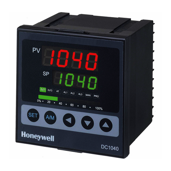
Configuration Operator Interface Upper Display 4 digits dedicated to display the PV. In configuration mode, this display indicates the name of parameter. Lower Display 4 digits dedicated to display the SP. In configuration mode, this display indicates the value of parameter or the status of parameter selected. Bar Graph A bargraph of 10 green LEDs’... -
Page 18: Mode Access
MODE Access Operation Configuration 1 Program Configuration 2 Set Up How to move from one MODE to another Press ‘SET’ key for 5 seconds; it grants access to ‘Configuration 1’ mode or return to ‘Operation’ mode from ‘Configuration 1’ mode. Press ‘SHIFT’... -
Page 19: Modes
MODEs 3.3.1 Operation Parameter Description PV Display SP Display Output Limit To limit the Maximum of Control Ouput Percentage (%) Auto Tuning Status * Default ‘No’ Alarm 1 Enter deviation value or absolute value Value of alarm setpoint Depending on alarm mode selected Alarm 2 The same with Alarm1 Alarm 3... -
Page 20: Configuration 1
3.3.2 Configuration 1 ‘Configuration 1’ will be shown by pressing ‘SET’ key for 5 seconds in ‘Operation’ mode. Parameter Description Main Control (OUT1) Range: 0~200% P value (Proportional Band) P1=0, ON/OFF Control Main Control (OUT1) Range: 0~3600 seconds I value (Integral Time) I=0, Integral off Main Control (OUT1) Range: 0~900 seconds... -
Page 21: Configuration 2
3.3.3 Configuration 2 ‘Configuration 2’ mode will be shown by pressing ‘SHIFT’ key for 5 seconds WHILE pressing ‘SET’ key FIRST in ‘Operation’ or ‘Configuration 2’ mode. Parameter Description Input 1 (INP1) To define input type & input range * Refer to Input 1 (INP1) To be used during the calibration for linear input Lower limit of linear Input... - Page 22 Parameter Description Main Control (OUT1) To adjust the linear control output during the calibration Lower limit of linear output * DO NOT change the value without technical support Main Control (OUT1) To adjust the linear control output during calibration Upper limit of linear output * DO NOT change the value without technical support Sub Control (OUT2) The same configuration method with ‘CL01’...
-
Page 23: Alarms
Parameter Description * DO NOT change the value Heating (direct) or Cooling (reverse) Operation Mode PID or Fuzzy Control Process 50 or 60Hz Frequency * Please, check whether the proper frequency is selected Alarms 3.4.1 Deviation Alarm The Alarm SP (Set Point) is to be changed as the SP moves. In this case, the Alarm SP preserves a certain deviation value with the SP. -
Page 24: Absolute Value Alarm
3.4.1.3 Lower Limit Deviation Alarm (Alarm Code 02, Alarm release in the first alarming situation) 3.4.1.4 Lower Limit Deviation Alarm (Alarm Code 12, No alarm release in the first alarming situation) 3.4.1.5 Dev. Band Breakaway Alarm(Alarm Code 03, Alarm release in the first alarming situation) 3.4.1.6 Dev. -
Page 25: Program Alarm
3.4.2.3 Absolute Lower Limit Alarm (Alarm Code 06, Alarm release in the first alarming situation) 3.4.2.4 Absolute Lower Limit Alarm (Alarm Code 16, No alarm release in the first alarming situation) 3.4.3 Program Alarm 3.4.3.1 Segment End Alarm (Alarm Code 07) Once the selected segment is completed, the alarm becomes actuated - ALD1 –... -
Page 26: Function Lock
Function Lock According to the status of the parameter “LCK” in ‘Configuration 1’ mode, ‘access to modes’ and ‘change of values’ can be prohibited. LCK=0000 MODE ACCESS Access to ‘Operation’, ‘Configuration1 & 2’ modes allowe (* Default) LCK=0100 MODE ACCESS Access to ‘Operation’... -
Page 27: Input Codes
Input Codes The input code in ‘Configuration 2’ mode must be selected properly before the operation starts. Thermocouples TYPE CODE RANGE 0.0~200.0°C 0.0~392.0°F 0.0~400.0°C 0.0~752.0°F 0~600°C 0~1112°F 0~800°C 0~1472°F 0~1000°C 0~1832°F 0~1200°C 0~2192°F 0.0~200.0°C 0.0~392.0°F 0.0~400.0°C 0.0~752.0°F 0~600°C 0~1112°F 0~800°C 0~1472°F 0~1000°C 0~1832°F... -
Page 28: Rtds
RTDs TYPE CODE RANGE -199.9~600.0°C -199.9~999.9°F -199.9~400.0°C -199.9~752.0°F -199.9~200.0°C -199.9~392.0°F Pt100 0~200°C 0~392°F 0~400°C 0~752°F 0~600°C 0~1112°F -199.9~600.0°C -199.9~999.9°F -199.9~400.0°C -199.9~752.0°F -199.9~200.0°C -199.9~392.0°F Pt100 0~200°C 0~392°F 0~400°C 0~752°F 0~600°C 0~1112°F -199.9~600.0°C -199.9~999.9°F -199.9~400.0°C -199.9~752.0°F -199.9~200.0°C -199.9~392.0°F Pt50 0~200°C 0~392°F 0~400°C 0~752°F 0~600°C 0~1112°F... -
Page 29: Operation
Operation Type of Control 5.1.1 Manual Operation The control output can be managed manually. When the ‘A/M’ key is pressed, the parameter of ‘OUTL’ will appear in the upper display, and a fixed control output is shown in lower display (% value). -
Page 30: Error Message
Error Message In case the following error messages appear in the upper display of controller, please refer to the Error message table below, or call technical support. See Contacts page for details. Sign Description Solution Open the circuit of ‘INPUT 1’ (sensor) Check the wiring A/D Convert Failure Service Call required... - Page 31 DC1010/1020/1030/1040 Product Manual...
- Page 32 Warranty/Remedy Honeywell warrants goods of its manufacture as being free of defective materials and faulty workmanship. Contact your local sales office for warranty information. If warranted goods are returned to Honeywell during the period of coverage, Honeywell will repair or replace without charge those items it finds defective.
Need help?
Do you have a question about the DC1000 SERIES and is the answer not in the manual?
Questions and answers