Allied Telesis AT-9724TS Installation And User Manual
High-density layer 3 stackable gigabit ethernet switch
Hide thumbs
Also See for AT-9724TS:
- Reference manual (282 pages) ,
- Datasheet (3 pages) ,
- Brochure (8 pages)
Table of Contents
Advertisement
Quick Links
High-Density Layer 3 Stackable Gigabit Ethernet Switch
AT-9724TS
Installation and User's Guide
PN D617/10032 Rev 1
Copyright. 2004 Allied Telesyn, Inc.
19800 North Creek Parkway, Suite 200, Bothell WA 98011, USA
All rights reserved. No part of this publication may be reproduced without prior written permission from Allied Telesyn,
Inc.All product names, company names, logos or other designations mentioned herein are trademarks or registered trademarks
of their respective owners.Allied Telesyn, Inc. reserves the right to make changes in specifications and other information
contained in this document without prior written notice.The information provided herein is subject to change
without notice. In no event shall Allied Telesyn Inc. be liable for any incidental, special, indirect, or consequential damages
whatsoever, including but not limited to lost profits, arising out of or related to this manual or the information contained
herein, even if Allied Telesyn, Inc. has been advised of, known, or should have known, the possibility of such damages.
Advertisement
Table of Contents

Related Manuals for Allied Telesis AT-9724TS


Summary of Contents for Allied Telesis AT-9724TS
- Page 1 High-Density Layer 3 Stackable Gigabit Ethernet Switch AT-9724TS Installation and User’s Guide PN D617/10032 Rev 1 Copyright. 2004 Allied Telesyn, Inc. 19800 North Creek Parkway, Suite 200, Bothell WA 98011, USA All rights reserved. No part of this publication may be reproduced without prior written permission from Allied Telesyn, Inc.All product names, company names, logos or other designations mentioned herein are trademarks or registered trademarks...
-
Page 2: Electrical Safety And Emission Statement
Obs! Bilaga B innehåller översatta säkerhetsmeddelanden avseende installationen av denna utrustning. När du ser, skall du gå till Bilaga A för att läsa det översatta säkerhetsmeddelandet på ditt språk. Allied Telesyn AT-9724TS High-Density Layer 3 Stackable Gigabit Ethernet Switch... -
Page 3: Table Of Contents
MST Configuration Table ..........................45 Allied Telesyn AT-9724TS High-Density Layer 3 Stackable Gigabit Ethernet Switch... - Page 4 PIM-DM Configuration..........................131 Allied Telesyn AT-9724TS High-Density Layer 3 Stackable Gigabit Ethernet Switch...
- Page 5 Appendix B Translated Electrical Safety and Emission Information ..................192 Allied Telesyn AT-9724TS High-Density Layer 3 Stackable Gigabit Ethernet Switch...
-
Page 6: Preface
Purpose of This Guide This guide is intended for network administrators who are responsible for installing and maintaining the AT-9724TS Gigabit Switch. How This Guide is Organized This guide contains the following chapters and appendices: Chapter 1, Introduction, describes the features, functions, LEDs, and ports on the Gigabit Switch. -
Page 7: Document Conventions
Indicates the menu structure. Device > Port > Port Properties means the Port Properties menu option under the Menu Option Port menu option that is located under the Device menu. Allied Telesyn AT-9724TS High-Density Layer 3 Stackable Gigabit Ethernet Switch... -
Page 8: Where To Find Related Guides
Fax: 1 425 481 3790 *Support for Puerto Rico and the US Virgin Islands is provided through our Technical Support Center in Latin America. México e-mail soporte_mexico@alliedtelesyn.com Teléfono +52 55 5559 0611 Allied Telesyn AT-9724TS High-Density Layer 3 Stackable Gigabit Ethernet Switch... -
Page 9: Returning Products
Allied Telesyn International S.r.l Kiriazi 14-16 145 62 Kifisia Tel: +30 210 6234 200 Fax: +30 210 6234 209 Allied Telesyn AT-9724TS High-Density Layer 3 Stackable Gigabit Ethernet Switch Italy – North Allied Telesyn International S.r.l. Via Anna Kuliscioff, 37 20152 Milano Tel: +39 02 41304.1... -
Page 10: Tell Us What You Think
Tell Us What You Think If you have any comments or suggestions on how we might improve this or other Allied Telesyn documents, please contact us at www.alliedtelesyn.com. Allied Telesyn AT-9724TS High-Density Layer 3 Stackable Gigabit Ethernet Switch... -
Page 11: Chapter 1 - Introduction
Allied Telesyn AT-9724TS High-Density Layer 3 Stackable Gigabit Ethernet Switch... -
Page 12: Switch Description
1000T ports. SFP ports will always have priority over these 1000T ports. Also included at the rear of the Switch are two 10-gigabit stacking ports used to stack up to twelve switches in a ring topology.The AT-9724TS may be used as the master unit of a switch stack when utilizing these ports and, in total, may provide a stacking solution of up to 288 gigabit ports. -
Page 13: Ports
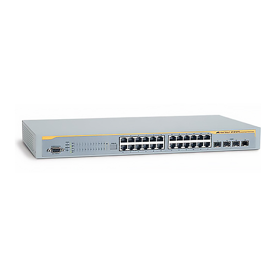
Allied Telesyn AT-9724TS High-Density Layer 3 Stackable Gigabit Ethernet Switch Figure 1- 1. Inserting the fibre-optic transceivers into the AT-9724TS Stack ID 13 15 19 21 14 16 20 22 Figure 1- 2. Front Panel View of the AT-9724TS as shipped... -
Page 14: Led Indicators
6 inches of space at the rear and sides of the Switch for proper ventilation. Be reminded that without proper heat dissipation and air circulation, system components might overheat, which could lead to system failure. Allied Telesyn AT-9724TS High-Density Layer 3 Stackable Gigabit Ethernet Switch Figure 1- 3. LED Indicators Figure 1- 4. -
Page 15: Chapter 2 - Installation
One AT-9724TS Switch • One AC power cord • One Stacking Cable • One CD which includes the AT-9724TS Manual, and Net.Cover documents • One Warranty Card • Mounting kit (two brackets and screws) • Four rubber feet with adhesive backing •... -
Page 16: Installing The Switch Without The Rack
The Switch can be mounted in a standard 19" rack. Use the following diagrams to guide you. Fasten the mounting brackets to the Switch using the screws provided.With the brackets attached securely, you can mount the Switch in a standard rack as shown in Figure 2-2. Allied Telesyn AT-9724TS High-Density Layer 3 Stackable Gigabit Ethernet Switch... -
Page 17: Installing The Switch In A Rack
As a precaution, in the event of a power failure, unplug the Switch.When power is resumed, plug the Switch back in. 2-7 External Redundant Power System The Switch supports an external redundant power system. Figure 2- 3.The AT-9724TS with the AT-RPS7000 Redundant External Power Supply Allied Telesyn AT-9724TS High-Density Layer 3 Stackable Gigabit Ethernet Switch... -
Page 18: Chapter 3 - Connecting The Switch
Figure 3- 2. Switch connected to a port on a hub or switch using either a straight or crossover cable – any normal cable is fine Allied Telesyn AT-9724TS High-Density Layer 3 Stackable Gigabit Ethernet Switch Figure 3- 1. Switch connected to an end node... -
Page 19: Connecting To Network Backbone Or Server
3-4 Stacking and the AT-9724TS The AT-9724TS is equipped with two 10-gigabit stacking ports at the rear of the Switch, as seen in Figure 3-5.These stacking ports may be used to stack the AT- 9724TS to a master switch to be used in a switch stack. -
Page 20: Stacking Limitations Utilizing A Ring Topology
Switch stack can cause a broadcast storm. Stacking Limitations Utilizing a Ring Topology There is a limit to the number of AT-9724TS Switches that can be stacked in a ring topology. A maximum of 12 switches can be stacked. Note: All Switches must have the same firmware rev. -
Page 21: Chapter 4 - Introduction To Switch Management
When you use HyperTerminal with the Microsoft® Windows® 2000 operating system, ensure that you have Windows 2000 Service Pack 2 or later installed.Windows 2000 Service Pack 2 allows you to use arrow keys in HyperTerminal's VT100 emulation. See www.microsoft.com for information on Windows 2000 service packs. Allied Telesyn AT-9724TS High-Density Layer 3 Stackable Gigabit Ethernet Switch... -
Page 22: First Time Connecting To The Switch
Enter the commands to complete your desired tasks. Many commands require administrator-level access privileges. Read the next section for more information on setting up user accounts. See the AT-9724TS Command Line Interface Reference Manual on the documentation CD for a list of all commands and additional information on using the CLI. -
Page 23: Password Protection
SNMP agent. SNMP defines both the format of the MIB specifications and the protocol used to access this information over the network. Allied Telesyn AT-9724TS High-Density Layer 3 Stackable Gigabit Ethernet Switch Figure 4- 2. Command Prompt... -
Page 24: Traps
The AT-9724TS supports SNMP versions 1, 2c, and 3.You can specify which version of SNMP you want to use to monitor and control the Switch.The three versions of SNMP vary in the level of security provided between the management station and the network device. -
Page 25: Connecting Devices To The Switch
Use the appropriate network cabling to connect a device to the connectors on the SFP transceiver. Caution: When the SFP transceiver acquires a link, the associated integrated 10/100/1000T port is disabled. Allied Telesyn AT-9724TS High-Density Layer 3 Stackable Gigabit Ethernet Switch Figure 4- 4.Assigning the Switch an IP Address... -
Page 26: Chapter 5 - Introduction To Web-Based Switch Configuration
5-1 Introduction All software functions of the AT-9724TS can be managed, configured and monitored via the embedded web-based (HTML) interface.The Switch can be managed from remote stations anywhere on the network through a standard browser such as Netscape Navigator/Communicator or Microsoft Internet Explorer.The browser acts as a universal access tool and can communicate directly with the Switch using the HTTP protocol. -
Page 27: Web-Based User Interface
Caution: Any changes made to the Switch configuration during the current session must be saved in the Save Changes web menu (explained below) or use the command line interface (CLI) command save. Allied Telesyn AT-9724TS High-Density Layer 3 Stackable Gigabit Ethernet Switch Figure 5- 2. Main Web-Manager Screen... -
Page 28: Web Pages
Single IP Management – Contains screens concerning information on Single IP Management, including SIM Settings,Topology and Firmware/Configuration downloads. Note: Be sure to configure the user name and password in the User Accounts menu before connecting the Switch to the greater network. Allied Telesyn AT-9724TS High-Density Layer 3 Stackable Gigabit Ethernet Switch... -
Page 29: Chapter 6 - Configuring The Switch
System Name, System Location and System Contact to aid in defining the Switch, to the user's preference. Allied Telesyn AT-9724TS High-Density Layer 3 Stackable Gigabit Ethernet Switch Figure 6- 1. Switch Information – Basic Settings window... -
Page 30: Ip Address
The IP Address may initially be set using the console interface prior to connecting to it through the Ethernet. If the Switch IP address has not yet been changed, read the introduction of the AT-9724TS Command Line Interface Reference Manual or return to Chapter 4 of this manual for more information. -
Page 31: Setting The Switch's Ip Address Using The Console Interface
Configuration folder.This will enable the following window to be viewed and configured. Allied Telesyn AT-9724TS High-Density Layer 3 Stackable Gigabit Ethernet Switch This allows the entry of a VLAN Name from which a management station will be allowed to manage the Switch using TCP/IP (in-band via web manager or Telnet). -
Page 32: Box Information
The Box Information Configuration screen can be found in the Configuration folder under the heading Box Information.This window is used to configure the Master switch of a switch stack.The Master switch is the switch that will be used to configure the software applications regarding the switch stack. Allied Telesyn AT-9724TS High-Density Layer 3 Stackable Gigabit Ethernet Switch Description Select the logout time used for the console interface.This automatically logs the user out after an idle period of... -
Page 33: Port Configurations
Choose the port or sequential range of ports using the From…To… port pull-down menus, and the Unit ID of the Switch to be configured. Use the remaining pull-down menus to configure the parameters described below: Allied Telesyn AT-9724TS High-Density Layer 3 Stackable Gigabit Ethernet Switch Description The current Box ID of the Master switch in the stack. -
Page 34: Port Description
Click Apply to implement the new settings on the Switch. 6-5 Port Description The AT-9724TS supports a port description feature where the user may name various ports on the Switch.To assign names to various ports, click the Port Description on the Configuration menu: Use the From and To pull down menu to choose a port or range of ports to describe and Unit to choose the Switch in the switch stack, and then enter a description of the port(s). -
Page 35: Port Mirroring
Port trunk groups are used to combine a number of ports together to make a single high-bandwidth data pipeline. The AT-9724TS supports up to 32 port trunk groups with 2 to 8 ports in each group.A potential bit rate of 8000Mbps can be achieved. - Page 36 Delete heading in the Current Link Aggregation Group Entries table. Allied Telesyn AT-9724TS High-Density Layer 3 Stackable Gigabit Ethernet Switch Figure 6- 9. Current Link Aggregation Group Entries window Figure 6- 10. Link Aggregation Group Configuration window – Add...
-
Page 37: Lacp Port Setting
LACP control frames. Allied Telesyn AT-9724TS High-Density Layer 3 Stackable Gigabit Ethernet Switch Figure 6- 11. Link Aggregation Group Configuration window – Modify Description Select an ID number for the group, between 1 and 32. -
Page 38: Mac Notification
History size Current MAC notification configurations can be viewed in the Current MAC Notification Global Settings window, as seen above. Allied Telesyn AT-9724TS High-Density Layer 3 Stackable Gigabit Ethernet Switch Description Choose the switch in the switch stack to be configured by using the pull-down menu. -
Page 39: Mac Notification Port Setting
IGMP version 1 is defined in RFC 1112. It has a fixed packet size and no optional data. Allied Telesyn AT-9724TS High-Density Layer 3 Stackable Gigabit Ethernet Switch Figure 6- 14. MAC Notification Port Settings and Port State Table Description Choose the Switch ID number of the Switch in the switch stack to be modified. - Page 40 Count Becomes Zero Leave Group Allied Telesyn AT-9724TS High-Density Layer 3 Stackable Gigabit Ethernet Switch Response Time Group Address (all zeros if this is a query) Figure 6- 15. IGMP Message Format Meaning Membership Query (if Group Address is 0.0.0.0)
-
Page 41: Igmp Snooping
VLAN ID VLAN Name Query Interval Max Response Time Allied Telesyn AT-9724TS High-Density Layer 3 Stackable Gigabit Ethernet Switch Figure 6- 17. Current IGMP Snooping Group Entries Figure 6- 18. IGMP Snooping Settings window Description This is the VLAN ID that, along with the VLAN Name, identifies the VLAN the user wishes to modify the IGMP Snooping Settings for. -
Page 42: Static Router Ports
Modify button.This will open the Static Router Ports Settings page, as shown below. Allied Telesyn AT-9724TS High-Density Layer 3 Stackable Gigabit Ethernet Switch Adjust this variable according to expected packet loss. If packet loss on the VLAN is expected to be high, the Robustness Variable should be increased to accommodate increased packet loss.This entry field allows an... -
Page 43: Member Ports
VLANs that will be shared must be added to the MSTP Instance ID (defined here as a VID List in the MST Configuration Table window when configuring an MSTI ID settings). Allied Telesyn AT-9724TS High-Density Layer 3 Stackable Gigabit Ethernet Switch Figure 6- 20. Static Router Ports Settings window... -
Page 44: Rapid Spanning Tree
STP Bridge Global Settings To open the following window, open the Spanning Tree folder in the Configuration menu and click the STP Bridge Global Settings link. Allied Telesyn AT-9724TS High-Density Layer 3 Stackable Gigabit Ethernet Switch 802.1w RSTP 802.1d STP... - Page 45 Figure 6- 21. STP Bridge Global Settings – STP compatible Figure 6- 22. STP Bridge Global Settings – RSTP (default) Figure 6- 23. STP Bridge Global Settings The following parameters can be set: Allied Telesyn AT-9724TS High-Density Layer 3 Stackable Gigabit Ethernet Switch...
-
Page 46: Mst Configuration Table
MSTI ID for, and cannot be deleted.To view the Current MST Configuration Identification window, click Configuration > Spanning Tree > MST Configuration Table: Allied Telesyn AT-9724TS High-Density Layer 3 Stackable Gigabit Ethernet Switch Description Use the pull-down menu to enable or disable STP globally on the Switch.The default is Disabled. - Page 47 To configure the settings for the CIST, click on its hyperlinked MSTI ID number in the Current MST Configuration Identification window, which will reveal the following window to configure: Allied Telesyn AT-9724TS High-Density Layer 3 Stackable Gigabit Ethernet Switch Description A previously configured name set on the Switch to uniquely identify the MSTI (Multiple Spanning Tree Instance).
- Page 48 Type VID List (1-4094) Click Apply to implement changes made. Allied Telesyn AT-9724TS High-Density Layer 3 Stackable Gigabit Ethernet Switch Description The MSTI ID of the CIST is 0 and cannot be altered. The type of configuration about to be processed.This window is used to add or delete VIDs to the configured MSTI or internal CIST.
-
Page 49: Msti Port Information
Instance ID Internal cost (0=Auto) Priority Click Apply to implement changes made. Allied Telesyn AT-9724TS High-Density Layer 3 Stackable Gigabit Ethernet Switch Figure 6- 28. MSTP Port Information window Figure 6- 29. MSTI Settings window Description Displays the MSTI ID of the instance being configured.An entry of 0 in this field denotes the CIST (default MSTI). -
Page 50: Stp Instance Settings
Click Apply to implement changes made. Clicking the hyperlinked name will allow the user to view the current parameters set for the MSTI Instance. Allied Telesyn AT-9724TS High-Density Layer 3 Stackable Gigabit Ethernet Switch Figure 6- 30. STP Instance Settings Description Displays the instance type(s) currently configured on the Switch. - Page 51 Forward Delay Last Topology Change Topology Changes Count Allied Telesyn AT-9724TS High-Density Layer 3 Stackable Gigabit Ethernet Switch Description This field will show the priority and MAC address of the Root Bridge. This defines a metric that indicates the relative cost of forwarding packets to the specified port list. Port cost can be set automatically or as a metric value.The default value is 0 (auto).
-
Page 52: Stp Port Settings
Unit From/To External Cost Allied Telesyn AT-9724TS High-Density Layer 3 Stackable Gigabit Ethernet Switch Figure 6- 33. STP Port Settings and MSTP Port Information Table Description Choose the Switch ID number of the Switch in the switch stack to be modified. -
Page 53: Forwarding & Filtering
Click Apply to implement the changes made.To delete an entry in the Static Unicast Forwarding Table, click the corresponding heading. Allied Telesyn AT-9724TS High-Density Layer 3 Stackable Gigabit Ethernet Switch 0 (auto) – Setting 0 for the external cost will automatically set the speed for forwarding packets to the specified port(s) in the list for optimal efficiency. -
Page 54: Static Multicast Forwarding
Click Apply to implement the changes made.To delete an entry in the Static Multicast Forwarding Table, click the corresponding heading. Click the Show All Multicast Forwarding Entries link to return to the Static Multicast Forwarding Settings window. Allied Telesyn AT-9724TS High-Density Layer 3 Stackable Gigabit Ethernet Switch Figure 6- 36. Setup Static Multicast Forwarding Table Description Choose the Switch ID number of the Switch in the switch stack to be modified. -
Page 55: Vlans
VLANs. The AT-9724TS supports IEEE 802.1Q VLANs and Port-Based VLANs. The port untagging function can be used to remove the 802.1Q tag from packet headers to maintain compatibility with devices that are tag-unaware.The Switch's default is to assign all ports to a single 802.1Q VLAN named "default."... -
Page 56: Q Vlan Tags
802.1Q standard. Because the VID is 12 bits long, 4094 unique VLANs can be identified. The tag is inserted into the packet header making the entire packet longer by 4 octets.All of the information originally contained in the packet is retained. Allied Telesyn AT-9724TS High-Density Layer 3 Stackable Gigabit Ethernet Switch Packet... - Page 57 Dest. Src. Length/EType Dest. Src. EType Priority Allied Telesyn AT-9724TS High-Density Layer 3 Stackable Gigabit Ethernet Switch Destination Address (6 Octets) Source Address (6 Octets) Tag Control Information Beginning of Data Cyclic Redundancy Check (4 Octets) VLAN ID (VID) 1 bit 12 bits Figure 6- 38.
-
Page 58: Port Vlan Id
If no VLANs are configured on the Switch, then all packets will be forwarded to any destination port. Packets with unknown source addresses will be flooded to all ports. Broadcast and multicast packets will also be flooded to all ports. Allied Telesyn AT-9724TS High-Density Layer 3 Stackable Gigabit Ethernet Switch... -
Page 59: Port-Based Vlans
Protocol VLANs The AT-9724TS incorporates the idea of protocol-based VLANs.This standard, defined by the IEEE 802.1v standard maps packets to protocol-defined VLANs by examining the type octet within the packet header to discover the type of protocol associated with it.After assessing the protocol, the Switch will forward the packets to all ports within the protocol-assigned VLAN.This feature will benefit the administrator by better balancing load sharing and enhancing traffic... -
Page 60: Static Vlan Entry
VLAN to forward packets to. Static VLAN Entry In the Configuration folder, open the VLAN folder and click the Static VLAN Entry link to open the following window: Allied Telesyn AT-9724TS High-Density Layer 3 Stackable Gigabit Ethernet Switch Type Header in Hexadecimal Form 0x0800... - Page 61 VLAN. See the table below for a description of the parameters in the new menu. Figure 6- 42. 802.1Q Static VLANs – Modify The following fields can then be set in either the Add or Modify 802.1Q Static VLANs menus: Allied Telesyn AT-9724TS High-Density Layer 3 Stackable Gigabit Ethernet Switch...
- Page 62 Advertisement Type Protocol ID Allied Telesyn AT-9724TS High-Density Layer 3 Stackable Gigabit Ethernet Switch Description Choose the Switch ID number of the Switch in the switch stack to be modified. Allows the entry of a VLAN ID in the Add dialog box, or displays the VLAN ID of an existing VLAN in the Modify dialog box.VLANs can be identified by either the VID or the VLAN name.
-
Page 63: Gvrp Setting
PVID does not match the PVID of the port. Results can be seen in the table under the configuration settings, as seen below. Allied Telesyn AT-9724TS High-Density Layer 3 Stackable Gigabit Ethernet Switch User Defined Pid – Specifies that the VLAN will only accept packets with this hexadecimal 802.1Q Ethernet type value in the packet header.The user may define an entry, in the hexadecimal form (ffff) to define the packet... -
Page 64: Traffic Control
Look Up Failure).Traffic control settings are applied to individual Switch modules. To view the following window, click Configuration > Traffic Control: Allied Telesyn AT-9724TS High-Density Layer 3 Stackable Gigabit Ethernet Switch Description Choose the Switch ID number of the Switch in the switch stack to be modified. -
Page 65: Port Security
Max. Learning Addr. (0-64) Mode Click Apply to implement changes made. Allied Telesyn AT-9724TS High-Density Layer 3 Stackable Gigabit Ethernet Switch Figure 6- 45. Port Security Settings and Port Security Table window Description Choose the Switch ID number of the Switch in the switch stack to be modified. -
Page 66: Port Lock Entries
Port Type Delete Allied Telesyn AT-9724TS High-Density Layer 3 Stackable Gigabit Ethernet Switch Figure 6- 46. Port Lock Entries Table Description The VLAN ID of the entry in the forwarding database table that has been permanently learned by the Switch. -
Page 67: Qos
6-18 QoS The AT-9724TS supports 802.1p priority queuing Quality of Service.The following section discusses the implementation of QoS (Quality of Service) and benefits of using 802.1p priority queuing. The Advantages of QoS QoS is an implementation of the IEEE 802.1p standard that allows network administrators a method of reserving bandwidth for important functions that require a large bandwidth or have a high priority, such as VoIP (voice-over Internet Protocol), web browsing applications, file server applications or video conferencing. -
Page 68: Bandwidth Control
CoS.The other CoS queues that have been given a nonzero value, and depending upon the weight, will follow a common weighted round-robin scheme. Remember that the AT-9724TS has 7 configurable priority queues (and seven Classes of Service) for each port on the Switch. -
Page 69: Qos Scheduling Mechanism
QoS settings are not suitable. In the Configuration folder open the QoS folder and click QoS Output Scheduling, to view the screen shown below. Allied Telesyn AT-9724TS High-Density Layer 3 Stackable Gigabit Ethernet Switch Description The highest queue is the first to process traffic.That is, the highest queue will finish before other queues empty. -
Page 70: Configuring The Combination Queue
Configuring the Combination Queue Utilizing the QoS Output Scheduling Configuration window shown above, the AT-9724TS can implement a combination queue for forwarding packets. This combination queue allows for a combination of strict and weight-fair (weighted round-robin “WRR”) scheduling for emptying given classes of service.To set the combination queue, enter a 0 for the Max Packets entry of the corresponding priority classes of service listed in the window above. -
Page 71: Default Priority
From and To pull-down menus and then insert a priority value, from 0-7 in the Priority field. Click Apply to implement your settings. 802.1p User Priority The AT-9724TS allows the assignment of classes of service to each of the 802.1p priorities. In the Configuration folder open the QoS folder and click 802.1p User Priority, to view the screen shown below. -
Page 72: Traffic Segmentation
This page allows you to determine which port on a given switch in a switch stack will be allowed to forward packets to other ports on that switch. Configuring traffic segmentation on the AT-9724TS is accomplished in two parts. First, you specify a switch from a switch stack by using the Unit pull-down menu, and then a port from that switch, using the Port pull-down menu.Then specify a second switch from the switch stack, and then you select which ports (or... -
Page 73: System Log Server
Index field. Both actions will result in the same screen to configure. See the table below for a description of the parameters in the following window. Figure 6- 57. System Log Servers – Add The following parameters can be set: Allied Telesyn AT-9724TS High-Density Layer 3 Stackable Gigabit Ethernet Switch... - Page 74 To set the System Log Server configuration, click Apply.To delete an entry from the Current System Log Server window, click the corresponding under the Delete heading of the entry to delete.To return to the Current System Log Servers window, click the Show All System Log Servers link. Allied Telesyn AT-9724TS High-Density Layer 3 Stackable Gigabit Ethernet Switch Description Syslog server settings index (1-4).
-
Page 75: Sntp Settings
Month Time in HH MM SS Click Apply to implement your changes. Allied Telesyn AT-9724TS High-Density Layer 3 Stackable Gigabit Ethernet Switch Figure 6- 58.Time Settings Page Description Displays the time when the Switch was initially started for this session. -
Page 76: Time Zone And Dst
To: Day To: Time in HH:MM Click Apply to implement changes made to the Time Zone and DST window. Allied Telesyn AT-9724TS High-Density Layer 3 Stackable Gigabit Ethernet Switch Figure 6- 59.Time Zone and DST Settings Page Description Use this pull-down menu to Enable or Disable the DST Settings. -
Page 77: Access Profile Table
Packet Content Mask.You can switch between the three Access Profile Configuration pages by using the Type drop-down menu. The page shown below is the Ethernet Access Profile Configuration page. Figure 6- 61.Access Profile Table (Ethernet) Allied Telesyn AT-9724TS High-Density Layer 3 Stackable Gigabit Ethernet Switch... - Page 78 Profile ID (1-8) Type VLAN Allied Telesyn AT-9724TS High-Density Layer 3 Stackable Gigabit Ethernet Switch Description Type in a unique identifier number for this profile set.This value can be set from 1 - 8. Select profile based on Ethernet (MAC Address), IP address or packet content mask.This will change the menu according to the requirements for the type of profile.
- Page 79 The page shown below is the Packet Content Mask configuration window. Figure 6- 63.Access Profile Configuration window (Packet Content Mask) Allied Telesyn AT-9724TS High-Density Layer 3 Stackable Gigabit Ethernet Switch Enter an IP address mask for the source IP address.
- Page 80 To create a new rule set for an access profile click the Add button. A new window is displayed.To remove a previously created rule, click the corresponding button. Allied Telesyn AT-9724TS High-Density Layer 3 Stackable Gigabit Ethernet Switch Description Type in a unique identifier number for this profile set.This value can be set from 1 - 8.
- Page 81 Protocol To view the settings of a previously correctly configured rule, click View in the Access Rule Table to view the following screen: Allied Telesyn AT-9724TS High-Density Layer 3 Stackable Gigabit Ethernet Switch Figure 6- 65.Access Rule Configuration window (IP) Description This is the identifier number for this profile set.
- Page 82 Access Rule, click the Add button: Figure 6- 68.Access Rule Configuration window – Ethernet To set the Access Rule for Ethernet, adjust the following parameters and click Apply. Allied Telesyn AT-9724TS High-Density Layer 3 Stackable Gigabit Ethernet Switch...
-
Page 83: Ethernet Type
To configure the Access Rule for Packet Content Mask, open the Access Profile Table and click Modify for a Packet Content Mask entry.This will open the following screen: Allied Telesyn AT-9724TS High-Density Layer 3 Stackable Gigabit Ethernet Switch Description This is the identifier number for this profile set. - Page 84 Mode Access ID Type Allied Telesyn AT-9724TS High-Density Layer 3 Stackable Gigabit Ethernet Switch Figure 6- 70.Access Rule Table (Packet Content Mask) button.To add a new Access Rule, click the Add button: Figure 6- 71.Access Rule Configuration – Packet Content Mask Description This is the identifier number for this profile set.
-
Page 85: Port Access Entity (802.1X)
Port and initiate the process of authenticating the attached device if the Port is unauthorized.This is the Port-Based Network Access Control. Allied Telesyn AT-9724TS High-Density Layer 3 Stackable Gigabit Ethernet Switch This parameter is specified if you want to re-write the 802.1p default priority previously set in the Switch, which is used to determine the CoS queue to which packets are forwarded to. -
Page 86: Port-Based Network Access Control
MAC addresses, and effectively creates a logical Port that the attached device can then use to communicate with the LAN via the Switch. Allied Telesyn AT-9724TS High-Density Layer 3 Stackable Gigabit Ethernet Switch AT-9724TS Switch 802.1X Client 802.1X Client... -
Page 87: Configure Authenticator
Port heading, which will display the following table to configure: Figure 6- 76. 802.1X Authenticator Settings – Modify Allied Telesyn AT-9724TS High-Density Layer 3 Stackable Gigabit Ethernet Switch... -
Page 88: Local Users
Enter a User Name, Password and confirmation of that password. Properly configured local users will be displayed in the 802.1x Local User Table in the same window. Allied Telesyn AT-9724TS High-Density Layer 3 Stackable Gigabit Ethernet Switch Description Choose the Switch ID number of the Switch in the switch stack to be modified. -
Page 89: Pae System Control
Unit From and To Capability Allied Telesyn AT-9724TS High-Density Layer 3 Stackable Gigabit Ethernet Switch Figure 6- 78. 802.1x Capability Settings and Table window Description Choose the Switch ID number of the Switch in the switch stack to be modified. -
Page 90: Initializing Ports For Port Based 802.1X
Auth PAE State Backend State Port Status Allied Telesyn AT-9724TS High-Density Layer 3 Stackable Gigabit Ethernet Switch Figure 6- 79. Initialize Port window (Port-based) Description Choose the Switch ID number of the Switch in the switch stack to be modified. -
Page 91: Initializing Ports For Mac Based 802.1X
Apply.The Reauthenticate Port Table displays the current status of the reauthenticated port(s) once you have clicked Apply. Click Port Access Entity > PAE System Control > Reauthenticate Port(s) to open the Reauthenticate Port(s) window: Allied Telesyn AT-9724TS High-Density Layer 3 Stackable Gigabit Ethernet Switch Figure 6- 80. Initialize Ports window (MAC based 802.1x) -
Page 92: Reauthenticate Port(S) For Mac Based 802.1X
MAC address to be reauthenticated by entering it into the MAC Address field and checking the corresponding check box.To begin the reauthentication, click Apply. Allied Telesyn AT-9724TS High-Density Layer 3 Stackable Gigabit Ethernet Switch Description Choose the Switch ID number of the Switch in the switch stack to be modified. -
Page 93: Radius Server
Accounting Port Confirm Key Status Click Apply to implement changes made. Allied Telesyn AT-9724TS High-Density Layer 3 Stackable Gigabit Ethernet Switch Description Choose the desired RADIUS server to configure: First, Second or Third. Set the RADIUS server IP. Set the RADIUS authentic server(s) UDP port.The default port is 1812. -
Page 94: Layer 3 Ip Networking
Any IP address from the allowed range of IP addresses for each subnet can be chosen as an IP address for an IP interface on the switch. For this example, we have chosen the next IP address above the network address for the IP interface’s IP Address: Allied Telesyn AT-9724TS High-Density Layer 3 Stackable Gigabit Ethernet Switch Figure 6- 84. L3 Global Advanced Settings window... -
Page 95: Network Number
To setup a new IP interface, click the Add button.To edit an existing IP Interface entry, click on an entry under the Interface Name heading. Both actions will result in the same screen to configure, as shown below. Allied Telesyn AT-9724TS High-Density Layer 3 Stackable Gigabit Ethernet Switch Network Number 10.32.0.0... -
Page 96: Md5 Key Table Configuration
MD5 Keys created here can be used in the OSPF Interface Configuration menu below. To configure an MD5 Key, click the MD5 Key link to open the following dialog box: Allied Telesyn AT-9724TS High-Density Layer 3 Stackable Gigabit Ethernet Switch Figure 6- 87. IP Interface Configuration – Edit window Description This field displays the name for the IP interface.The default IP interface is named “System”. -
Page 97: Route Redistribution Settings
Switch can redistribute routing information between the OSPF and RIP routing protocols to all routers on the network that are running OSPF or RIP. Routing information entered into the Static Routing Table on the local AT-9724TS switch is also redistributed. -
Page 98: Static/Default Route
Delete To enter an IP Interface into the Switch’s Static/Default Routes window, click the Add button, revealing the following window to configure. Allied Telesyn AT-9724TS High-Density Layer 3 Stackable Gigabit Ethernet Switch Description Allows for the selection of the protocol for the destination device. Choose between RIP and OSPF. -
Page 99: Route Preference Settings
If the user is not fully aware of all the features and functions of the routing protocols on the switch, a change in the default route preference value may cause routing loops or black holes. Allied Telesyn AT-9724TS High-Density Layer 3 Stackable Gigabit Ethernet Switch Figure 6- 91. Static/Default Route Settings – Add window Description Allows the entry of an IP address that will be a static entry into the Switch’s Routing Table. - Page 100 OSPF ExtT1 (1-999) OSPF ExtT2 (1-999) Click Apply to implement changes made. Allied Telesyn AT-9724TS High-Density Layer 3 Stackable Gigabit Ethernet Switch Figure 6- 92. Current and New Route Preference Settings window Description Enter a value between 1 and 999 to set the route preference for RIP.The lower the value, the higher the chance the specified protocol will be chosen as the best path for routing packets.The default value is 100.
-
Page 101: Static Arp Table
RIP does not have an explicit method to detect routing loops. Many RIP implementations include an authorization mechanism (a password) to prevent a router from learning erroneous routes from unauthorized routers. Allied Telesyn AT-9724TS High-Density Layer 3 Stackable Gigabit Ethernet Switch Figure 6- 93. Static ARP Settings window Figure 6- 94. -
Page 102: Rip Command Codes
Because the version number in RIP2 occupies the same octet as in RIP1, both versions of the protocols can be used on a given router simultaneously without interference. RIP Configuration Allied Telesyn AT-9724TS High-Density Layer 3 Stackable Gigabit Ethernet Switch Meaning Request for partial or full routing information Response containing network-distance pairs from sender’s routing table... -
Page 103: Setting Up Rip
Figure 6- 97. RIP Interface Settings – Edit window Refer to the table below for a description of the available parameters for RIP interface settings. The following RIP settings can be applied to each IP interface: Allied Telesyn AT-9724TS High-Density Layer 3 Stackable Gigabit Ethernet Switch... -
Page 104: Ospf
Cost = 100,000,000 / bandwidth in bps As an example, the cost of a 10Mbps Ethernet line will be 10 and the cost to cross a 1.544Mbps T1 line will be 64. Allied Telesyn AT-9724TS High-Density Layer 3 Stackable Gigabit Ethernet Switch Description The name of the IP interface on which RIP is to be setup.This interface must be previously configured on the... -
Page 105: Shortest Path Tree
10+5+10=25, but the cost is higher than the route through Router C.This higher-cost route will not be included in the Router A’s shortest path tree.The resulting tree will look like this: Allied Telesyn AT-9724TS High-Density Layer 3 Stackable Gigabit Ethernet Switch Router A 128.213.0.0... - Page 106 External link-state updates carry routing information to networks outside the Autonomous System.The Autonomous System Border Router is responsible for generating and distributing these updates. Allied Telesyn AT-9724TS High-Density Layer 3 Stackable Gigabit Ethernet Switch Router A 128.213.0.0 Router B 192.213.11.0...
-
Page 107: Ospf Authentication
Stub Area Flag – Any two routers also have to have the same stub area flag in their Hello packets in order to become neighbors. • Allied Telesyn AT-9724TS High-Density Layer 3 Stackable Gigabit Ethernet Switch... -
Page 108: Designated Router Election
Every OSPF packet is preceded by a common 24-byte header.This header contains the information necessary for a receiving router to determine if the packet should be accepted for further processing. The format of the OSPP packet header is shown below: Allied Telesyn AT-9724TS High-Density Layer 3 Stackable Gigabit Ethernet Switch... -
Page 109: Hello Packet
These parameters are included in hello packets, so that differences can inhibit the forming of neighbor relationships.A detailed explanation of the receive processing for Hello packets, so that differences can inhibit the forming of neighbor relationships. The format of the Hello packet is shown below: Allied Telesyn AT-9724TS High-Density Layer 3 Stackable Gigabit Ethernet Switch Type Router ID... - Page 110 Database Description packets (polls) that are acknowledged by Database Description packets sent by the slave (responses).The responses are linked to the polls via the packets’ DD sequence numbers. Allied Telesyn AT-9724TS High-Density Layer 3 Stackable Gigabit Ethernet Switch Router ID...
- Page 111 LS age, although these fields are not specified in the Link-State Request packet itself.The router may receive even more recent instances in response. The format of the Link-State Request packet is shown below: Allied Telesyn AT-9724TS High-Density Layer 3 Stackable Gigabit Ethernet Switch Router ID Area ID...
- Page 112 The body of the Link-State Update packet consists of a list of link-state advertisements. Each advertisement begins with a common 20-byte header, the link-state advertisement header. Otherwise, the format of each of the five types of link-state advertisements is different. Allied Telesyn AT-9724TS High-Density Layer 3 Stackable Gigabit Ethernet Switch Router ID...
-
Page 113: Link-State Advertisement Formats
Router Links Advertisements • Network Links Advertisements • Summary Link Advertisements • Autonomous System Link Advertisements Allied Telesyn AT-9724TS High-Density Layer 3 Stackable Gigabit Ethernet Switch Router ID Area ID Checksum Authentication Authentication Link-State Advertisement Header Figure 6- 105. Link State Acknowledge Packet... -
Page 114: Router Links Advertisements
The format of the Router Links Advertisement is shown below: Allied Telesyn AT-9724TS High-Density Layer 3 Stackable Gigabit Ethernet Switch Link State Age... - Page 115 IP interface address. Field Type Link ID Link Data No. of TOS TOS 0 Metric Allied Telesyn AT-9724TS High-Density Layer 3 Stackable Gigabit Ethernet Switch Link-State Age Options Link-State ID Advertising Router Link-State Sequence Number Link-State Checksum...
-
Page 116: Network Links Advertisements
When the destination is an AS boundary router, a Type 4 advertisement is used, and the Link State ID field is the AS boundary router’s OSPF Router ID. Other that the difference in the Link State ID field, the format of Type 3 and 4 link state advertisements is identical. Allied Telesyn AT-9724TS High-Density Layer 3 Stackable Gigabit Ethernet Switch Description IP Type of Service that this metric refers to. -
Page 117: Network Mask
Link Stat ID is always set the Default Destination address (0.0.0.0) and the Network Mask is set to 0.0.0.0. The format of the AS External Link Advertisement is shown below: AS External Link Advertisements Octets Allied Telesyn AT-9724TS High-Density Layer 3 Stackable Gigabit Ethernet Switch Link-State Age Link-State ID Advertising Router... -
Page 118: General Ospf Settings
To set up an OSPF Area configuration click Configuration > Layer 3 IP Networking > OSPF > OSPF Area ID Settings link to open the following dialog box: Allied Telesyn AT-9724TS High-Density Layer 3 Stackable Gigabit Ethernet Switch Description The IP address mask for the advertised destination. -
Page 119: Ospf Interface Settings
If there are no IP interfaces configured (besides the default System interface), only the System interface settings will appear listed.To change settings for in IP interface, click on the hyperlinked name of the interface to see the configuration menu for that interface. Allied Telesyn AT-9724TS High-Density Layer 3 Stackable Gigabit Ethernet Switch in the Delete column for the configuration. - Page 120 DR Address Backup DR Address Transmit Delay Retransmit Time Allied Telesyn AT-9724TS High-Density Layer 3 Stackable Gigabit Ethernet Switch Figure 6- 115. OSPF Interface Settings – Edit window Description Displays the of an IP interface previously configured on the Switch.
-
Page 121: Ospf Virtual Interface Settings
Dead Interval. For networks using authorization for OSPF devices, the Authorization Type and Password or Key used must likewise be identical. Allied Telesyn AT-9724TS High-Density Layer 3 Stackable Gigabit Ethernet Switch Figure 6- 116. OSPF Virtual Interface Settings window Figure 6- 117. -
Page 122: Ospf Area Aggregation Settings
OSPF host routes work in a way analogous to RIP, only this is used to share OSPF information with other OSPF routers.This is used to work around problems that might prevent OSPF information sharing between routers. Allied Telesyn AT-9724TS High-Density Layer 3 Stackable Gigabit Ethernet Switch in the Delete column for the configuration being removed. -
Page 123: Dhcp / Bootp Relay
DHCP / BOOTP Relay Information To enable and configure BOOTP or DHCP on the Switch, click Configuration > DHCP/BOOTP Relay > DHCP/BOOTP Global Settings: Allied Telesyn AT-9724TS High-Density Layer 3 Stackable Gigabit Ethernet Switch Figure 6- 120. OSPF Host Route Settings window Figure 6- 121. -
Page 124: Dhcp/Bootp Relay Settings
For two DNS servers to communicate across different subnets, the DNS Relay of the Switch must be used.The DNS servers are identified by IP addresses. Allied Telesyn AT-9724TS High-Density Layer 3 Stackable Gigabit Ethernet Switch Figure 6- 122. DHCP/BootP Global Settings window Description This field can be toggled between Enabled and Disabled using the pull-down menu. -
Page 125: Mapping Domain Names To Addresses
To view the DNS Relay Static Settings, open the DNS Relay folder in the Configuration folder and click the DNS Relay Static Settings link, which will open the following window. Allied Telesyn AT-9724TS High-Density Layer 3 Stackable Gigabit Ethernet Switch Figure 6- 124. DNS Global Settings window... -
Page 126: Vrrp
Parameter Global VRRP Non-owner response PING Click Apply to implement changes made. Allied Telesyn AT-9724TS High-Density Layer 3 Stackable Gigabit Ethernet Switch Figure 6- 125. DNS Relay Static Settings and Table window Figure 6- 126.VRRP Global Settings window Description Use the pull-down menu to enable or disable VRRP globally on the Switch.The default is Disabled. -
Page 127: Vrrp Interface Settings
Or, the user may click the hyperlinked Interface Name to view the same window: The following parameters may be set to configure an existing or new VRRP interface. Allied Telesyn AT-9724TS High-Density Layer 3 Stackable Gigabit Ethernet Switch Figure 6- 127.VRRP Configuration window Description An IP interface name that has been enabled for VRRP.This entry must have been previously set in the IP... - Page 128 Click Apply to implement changes made. To view the settings for a particular VRRP setting, click the corresponding View in the VRRP Interface Table of the entry, which will display the following: Allied Telesyn AT-9724TS High-Density Layer 3 Stackable Gigabit Ethernet Switch Description Enter the name of a previously configured IP interface to create a VRRP entry for.This IP interface must be...
- Page 129 Advertisement Interval Preempt Mode Virtual Router Up Time Allied Telesyn AT-9724TS High-Density Layer 3 Stackable Gigabit Ethernet Switch Figure 6- 129.VRRP Interface Entry Display window Description An IP interface name that has been enabled for VRRP.This entry must have been previously set in the IP Interface Settings table.
-
Page 130: Ip Multicast Routing Protocol
Max Response Time Robustness Variable Last Member Query Interval State Allied Telesyn AT-9724TS High-Density Layer 3 Stackable Gigabit Ethernet Switch Figure 6- 130. IGMP Interface Table Figure 6- 131. IGMP Interface Configuration window Description Displays the name of the IP interface that is to be configured for IGMP.This must be a previously configured IP interface. -
Page 131: Dvmrp Interface Configuration
Switch is displayed in the below DVMRP Interface Configuration dialog box.To configure DVMRP for a particular interface, click the corresponding hyperlink for that IP interface.This will open the DVMRP Interface Configuration window: Figure 6- 133. DVMRP Interface Settings window Figure 6- 134. DVMRP Interface Settings – Edit window Allied Telesyn AT-9724TS High-Density Layer 3 Stackable Gigabit Ethernet Switch... -
Page 132: Pim-Dm Interface Configuration
Use the pull down menu, choose Enabled, and click Apply to set the PIM-DM function on the Switch. Allied Telesyn AT-9724TS High-Density Layer 3 Stackable Gigabit Ethernet Switch Description Displays the name of the IP interface for which DVMRP is to be configured.This must be a previously defined IP interface. -
Page 133: Pim-Dm Interface Configuration
State Click Apply to implement changes made. Click Show All PIM-DM Interface Entries to return to the PIM-DM Interface Table. Allied Telesyn AT-9724TS High-Density Layer 3 Stackable Gigabit Ethernet Switch Figure 6- 136. PIM-DM Interface Settings window Figure 6- 137. PIM-DM Interface Settings window – Modify Description Allows the entry of the name of the IP interface for which PIM-DM is to be configured.This must be a... -
Page 134: Chapter 7 - Security Management
To add a new user, click on the Add button.To modify or delete an existing user, click on the Modify button for that user. Allied Telesyn AT-9724TS High-Density Layer 3 Stackable Gigabit Ethernet Switch Figure 7- 1. Security IP Management window... -
Page 135: Admin And User Privileges
After establishing a User Account with Admin-level privileges, be sure to save the changes by opening the Maintenance folder, opening the Save Changes window and clicking the Save Configuration button. Allied Telesyn AT-9724TS High-Density Layer 3 Stackable Gigabit Ethernet Switch Figure 7- 3. User Accounts Modify Table – Add Figure 7- 4. -
Page 136: Access Authentication Control
Method List and choose a technique for user authentication upon login. To access the following window, click Security Management > Access Authentication Control > Policy & Parameters: Allied Telesyn AT-9724TS High-Density Layer 3 Stackable Gigabit Ethernet Switch Figure 7- 5. Policy & Parameters Settings window... -
Page 137: Application's Authentication Settings
Up to eight (8) authentication server hosts may be added to any particular group. To view the following window, click Security Management > Access Authentication Control > Authentication Server Group: Allied Telesyn AT-9724TS High-Density Layer 3 Stackable Gigabit Ethernet Switch Description Use the pull down menu to enable or disable the Authentication Policy on the Switch. - Page 138 The built-in server groups can only have server hosts running the same TACACS or RADIUS daemon.TACACS/XTACACS/TACACS+ protocols are separate entities and are not compatible with each other. Allied Telesyn AT-9724TS High-Density Layer 3 Stackable Gigabit Ethernet Switch Figure 7- 7.Authentication Server Group Settings window Figure 7- 8.Add a Server Host to Server Group (XTACACS) window.
-
Page 139: Authentication Server Hosts
Port (1-65535) Timeout (1-255) Retransmit (1-255) Click Apply to add the server host. Allied Telesyn AT-9724TS High-Density Layer 3 Stackable Gigabit Ethernet Switch Figure 7- 10.Authentication Server Host Settings window Figure 7- 11.Authentication Server Host Setting window – Add Description The IP address of the remote server host the user wishes to add. -
Page 140: Login Method Lists
To configure a new Method List, click the Add button. Both actions will result in the same screen to configure: Allied Telesyn AT-9724TS High-Density Layer 3 Stackable Gigabit Ethernet Switch Figure 7- 12. Login Method Lists Settings window Figure 7- 13. Login Method List – Edit (default) -
Page 141: Enable Method Lists
Enable Method List, click on its hyperlinked Method List Name.To configure a Method List, click the Add button. Both actions will result in the same screen to configure: Allied Telesyn AT-9724TS High-Density Layer 3 Stackable Gigabit Ethernet Switch Description Enter a method list name defined by the user of up to 15 characters. -
Page 142: Local Enable Password
Switch. To view the following window, click Security Management > Access Authentication Control > Local Enable Password: Allied Telesyn AT-9724TS High-Density Layer 3 Stackable Gigabit Ethernet Switch Figure 7- 16. Enable Method List – Edit window Figure 7- 17. -
Page 143: Enable Admin
When this screen appears, click the Enable Admin button revealing a window for the user to enter authentication (password, username), as seen below. A successful entry will promote the user to Administrator level privileges on the Switch. Allied Telesyn AT-9724TS High-Density Layer 3 Stackable Gigabit Ethernet Switch Figure 7- 18. Configure Local Enable Password window Description If a password was previously configured for this entry, enter it here in order to change it to a new password. -
Page 144: Secure Socket Layer (Ssl)
Server IP Certificate File Name Key File Name Allied Telesyn AT-9724TS High-Density Layer 3 Stackable Gigabit Ethernet Switch Figure 7- 21. Download Certificate window Description Enter the type of certificate to be downloaded.This type refers to the server responsible for issuing certificates.This field has been limited to local for this firmware release. -
Page 145: Configuration
Certain implementations concerning the function and configuration of SSL are not available on the web-based management of this Switch and need to be configured using the command line interface. For more information on SSL and its functions, see the AT-9724TS Command Line Reference Manual, located on the documentation CD of this product. -
Page 146: Secure Shell (Ssh)
To open the following window, click Security Management > Secure Shell (SSH) > SSH Algorithm: Allied Telesyn AT-9724TS High-Density Layer 3 Stackable Gigabit Ethernet Switch Figure 7- 23. Current and New SSH Configuration Settings Description Use the pull-down menu to enable or disable SSH on the Switch.The default is Disabled. -
Page 147: Encryption Algorithm
Cast128-CBC Twofish128 Twofish192 Twofish256 Allied Telesyn AT-9724TS High-Density Layer 3 Stackable Gigabit Ethernet Switch Figure 7- 24. SSH Algorithms window Description This field may be enabled or disabled to choose if the administrator wishes to use a locally configured password for authentication on the Switch.This field is Enabled by default. -
Page 148: Ssh User Authentication
Current Accounts window, which will reveal the following window to configure. The user may set the following parameters: Allied Telesyn AT-9724TS High-Density Layer 3 Stackable Gigabit Ethernet Switch Use the pull-down to enable or disable the HMAC (Hash for Message Authentication Code) mechanism utilizing the Secure Hash algorithm.The default is Enabled. - Page 149 To set the SSH User Authentication parameters on the Switch, a User Account must be previously configured. For more information on configuring local User Accounts on the Switch, see the User Accounts section of this manual located in this section. Allied Telesyn AT-9724TS High-Density Layer 3 Stackable Gigabit Ethernet Switch Description Enter a User Name of no more than 15 characters to identify the SSH user.This User Name must be a...
-
Page 150: Chapter 8 - Snmp Manager
The AT-9724TS supports the SNMP versions 1, 2c, and 3.You can specify which version of the SNMP you want to use to monitor and control the Switch.The three versions of SNMP vary in the level of security provided between the management station and the network device. - Page 151 To add a new entry to the SNMP User Table Configuration, click on the Add button on the SNMP User Table page. This will open the SNMP User Table Configuration page, as shown below. The following parameters can be set: Allied Telesyn AT-9724TS High-Density Layer 3 Stackable Gigabit Ethernet Switch Figure 8- 2. SNMP User Table Display window Description An alphanumeric string of up to 32 characters.This is used to identify the SNMP users.
-
Page 152: Snmp View Table
To delete an existing SNMP View Table entry, click the the Add button and a separate menu will appear. Allied Telesyn AT-9724TS High-Density Layer 3 Stackable Gigabit Ethernet Switch Description Enter an alphanumeric string of up to 32 characters.This is used to identify the SNMP user. -
Page 153: View Type
To add a new entry to the Switch's SNMP Group Table, click the Add button in the upper left-hand corner of the SNMP Group Table page.This will open the SNMP Group Table Configuration page, as shown below. Allied Telesyn AT-9724TS High-Density Layer 3 Stackable Gigabit Ethernet Switch Figure 8- 5. SNMP View Table Configuration window Description Type an alphanumeric string of up to 32 characters.This is used to identify the new SNMP view being created. -
Page 154: Security Model
To configure SNMP Community entries, open the SNMP Manager folder and click the SNMP Community Table link, which will open the following screen: Allied Telesyn AT-9724TS High-Density Layer 3 Stackable Gigabit Ethernet Switch Figure 8- 7. SNMP Group Table Configuration window Description Type an alphanumeric string of up to 32 characters.This is used to identify the new SNMP group of SNMP... -
Page 155: Community Name
To add a new entry to the Switch's SNMP Host Table, click the Add button in the upper left-hand corner of the page.This will open the SNMP Host Table Configuration page, as shown below. Allied Telesyn AT-9724TS High-Density Layer 3 Stackable Gigabit Ethernet Switch Figure 8- 8. SNMP Community Table Configuration and Table window Description Type an alphanumeric string of up to 33 characters that is used to identify members of an SNMP community. -
Page 156: Snmp Engine Id
Configuration window, as shown below. To change the Engine ID, type the new Engine ID in the space provided and click the Apply button. Allied Telesyn AT-9724TS High-Density Layer 3 Stackable Gigabit Ethernet Switch Figure 8-10. SNMP Host Table Configuration window Description Type the IP address of the remote management station that will serve as the SNMP host for the Switch. -
Page 157: Chapter 9 - Monitoring
The CPU Utilization displays the percentage of the CPU being used, expressed as an integer percentage and calculated as a simple average by time interval.To view the CPU Utilization window, open the Monitoring folder and click the CPU Utilization link. Allied Telesyn AT-9724TS High-Density Layer 3 Stackable Gigabit Ethernet Switch Figure 9- 1. Port Utilization window Description Select the desired setting between 1s and 60s, where "s"... -
Page 158: Packets
Switch and/or switch stack at the top of the web page by simply clicking on a port. Allied Telesyn AT-9724TS High-Density Layer 3 Stackable Gigabit Ethernet Switch Figure 9- 2. CPU Utilization graph Description Select the desired setting between 1s and 60s, where "s"... - Page 159 To view the Received Packets Table, click the link View Table, which will show the following table: Figure 9- 4. Rx Packets Analysis window (table for Bytes and Packets) The following fields may be set or viewed: Allied Telesyn AT-9724TS High-Density Layer 3 Stackable Gigabit Ethernet Switch...
-
Page 160: Umb Cast (Rx)
Figure 9- 5. Rx Packets Analysis window (line graph for Unicast, Multicast, and Broadcast Packets) To view the UMB Cast Table, click the View Table link, which will show the following table: Allied Telesyn AT-9724TS High-Density Layer 3 Stackable Gigabit Ethernet Switch Description Select the desired setting between 1s and 60s, where "s"... -
Page 161: Transmitted (Tx)
Switch and/or switch stack at the top of the web page by simply clicking on a port. Allied Telesyn AT-9724TS High-Density Layer 3 Stackable Gigabit Ethernet Switch Description Select the desired setting between 1s and 60s, where "s"... - Page 162 Figure 9- 7.Tx Packets Analysis window (line graph for Bytes and Packets) To view the Transmitted (TX) Table, click the link View Table, which will show the following table: Figure 9- 8.Tx Packets Analysis window (table for Bytes and Packets) Allied Telesyn AT-9724TS High-Density Layer 3 Stackable Gigabit Ethernet Switch...
-
Page 163: Errors
Switch and/or switch stack at the top of the web page by simply clicking on a port. To view the Received Error Packets Table, click the link View Table, which will show the following table: Allied Telesyn AT-9724TS High-Density Layer 3 Stackable Gigabit Ethernet Switch Description Select the desired setting between 1s and 60s, where "s"... -
Page 164: Transmitted (Tx)
Switch and/or switch stack at the top of the web page by simply clicking on a port. Allied Telesyn AT-9724TS High-Density Layer 3 Stackable Gigabit Ethernet Switch Figure 9- 10. Rx Error Analysis window (table) Description Select the desired setting between 1s and 60s, where "s"... - Page 165 To view the Transmitted Error Packets Table, click the link View Table, which will show the following table: Figure 9- 12.Tx Error Analysis window (table) The following fields may be set or viewed: Allied Telesyn AT-9724TS High-Density Layer 3 Stackable Gigabit Ethernet Switch...
-
Page 166: Size
To view the Packet Size Analysis Table, click the link View Table, which will show the following table: Allied Telesyn AT-9724TS High-Density Layer 3 Stackable Gigabit Ethernet Switch Description Select the desired setting between 1s and 60s, where "s" stands for seconds.The default value is one second. -
Page 167: Stacking Information
When the switches are properly interconnected through their optional Stacking Modules, information about the resulting switch stack is displayed under the Stack Information link. To view the stacking information, click on the Stacking Information link from the Monitoring folder: Allied Telesyn AT-9724TS High-Density Layer 3 Stackable Gigabit Ethernet Switch Figure 9- 14. Rx Size Analysis window (table) Description Select the desired setting between 1s and 60s, where "s"... -
Page 168: Device Status
Denotes whether a switch does or does not exist in a stack. Displays the priority ID of the Switch.The lower the number, the higher the priority.The box (switch) with the lowest priority number in the stack denotes the Master switch.The AT-9724TS will always be the master switch in a Star topology. -
Page 169: Internal Power
Switch. To view the MAC Address forwarding table, from the Monitoring menu, click the MAC Address link: Allied Telesyn AT-9724TS High-Density Layer 3 Stackable Gigabit Ethernet Switch Figure 9- 16. Device Status window Description The Box ID of the Switch in the switch stack. -
Page 170: Switch History Log
Next to go to the next page of the Switch History Log. Clicking Clear will allow the user to clear the Switch History Log. The information is described as follows: Allied Telesyn AT-9724TS High-Density Layer 3 Stackable Gigabit Ethernet Switch Description Enter a VLAN Name for the forwarding table to be browsed by. -
Page 171: Igmp Snooping Group
Port Member Note: To configure IGMP snooping for the AT-9724TS, go to the Configuration folder and select IGMP Snooping. Configuration and other information concerning IGMP snooping may be found in Section 6 of this manual under IGMP. 9-9 IGMP Snooping Forwarding This window will display the current IGMP snooping forwarding table entries currently configured on the Switch.To view the following screen, open the... -
Page 172: Browse Router Port
The following section describes the 802.1X Status on the Switch.To view the Authenticator State, click Monitoring > Port Access Control > Authenticator State. Allied Telesyn AT-9724TS High-Density Layer 3 Stackable Gigabit Ethernet Switch Description The VLAN Name of the multicast group. -
Page 173: Authenticator Statistics
This table contains the statistics objects for the Authenticator PAE associated with each port.An entry appears in this table for each port that supports the Authenticator function.To view the Authenticator Statistics, click Monitoring > Port Access Control > Authenticator Statistics. Allied Telesyn AT-9724TS High-Density Layer 3 Stackable Gigabit Ethernet Switch Figure 9- 23.Authenticator State – MAC Based 802.1X... - Page 174 Rx Invalid Rx Error Last Version Last Source Allied Telesyn AT-9724TS High-Density Layer 3 Stackable Gigabit Ethernet Switch Figure 9- 24.Authenticator Statistics window Description The identification number assigned to the Port by the System in which the Port resides. The number of valid EAPOL frames that have been received by this Authenticator.
-
Page 175: Authenticator Session Statistics
Authentic Method Time Terminate Cause UserName Allied Telesyn AT-9724TS High-Density Layer 3 Stackable Gigabit Ethernet Switch Figure 9- 25.Authenticator Session Statistics window Description The identification number assigned to the Port by the System in which the Port resides. The number of octets received in user data frames on this port during the session. -
Page 176: Authenticator Diagnostics
Auth Reauth Auth Start Auth LogOff Authed Reauth Allied Telesyn AT-9724TS High-Density Layer 3 Stackable Gigabit Ethernet Switch Figure 9- 26.Authenticator Diagnostics window Description The identification number assigned to the Port by the System in which the Port resides. Counts the number of times that the state machine transitions to the CONNECTING state from any other state. -
Page 177: Radius Authentication
AccessRejects AccessChallenges AccessResponses Allied Telesyn AT-9724TS High-Density Layer 3 Stackable Gigabit Ethernet Switch Counts the number of times that the state machine transitions from AUTHENTICATED to CONNECTING, as a result of an EAPOL-Start message being received from the Supplicant. Counts the number of times that the state machine transitions from AUTHENTICATED to DISCONNECTED, as a result of an EAPOL-Logoff message being received from the Supplicant. -
Page 178: Radius Accounting
Timeouts UnknownTypes PacketsDropped Allied Telesyn AT-9724TS High-Density Layer 3 Stackable Gigabit Ethernet Switch The number of RADIUS Access-Response packets containing invalid authenticators or Signature attributes received from this server. The number of RADIUS Access-Request packets destined for this server that have not yet timed out or received a response.This variable is incremented when an Access-Request is sent and decremented due to... -
Page 179: Layer 3 Feature
Note: To configure 802.1x features for the AT-9724TS, go to the Configuration folder and select Port Access Entity. Configuration and other information concerning 802.1x may be found in Section 6 of this manual under Port Access Entity. 9-12 Layer 3 Feature This folder in the Monitoring section will display information concerning settings configured in Layer 3 IP Networking of the Configuration folder. -
Page 180: Browse Routing Table
IP multicasting information on the Switch.To search a specific entry, enter an multicast group IP address into the Multicast Group field or a Source IP address and click Find. Allied Telesyn AT-9724TS High-Density Layer 3 Stackable Gigabit Ethernet Switch... -
Page 181: Browse Igmp Group Table
If Adv. Router ID is selected, you must enter the IP address in the Advertisement Router ID field, and then click Find. If LSDB is selected, you must select the type of link state (RtrLink, NetLink, Summary, ASSummary and ASExtLink) in the LSDB Type field, and then click Find. Allied Telesyn AT-9724TS High-Density Layer 3 Stackable Gigabit Ethernet Switch... -
Page 182: Browse Ospf Neighbor Table
Parameter Transit Area ID Neighbor ID Allied Telesyn AT-9724TS High-Density Layer 3 Stackable Gigabit Ethernet Switch Description Allows the entry of an OSPF Area ID.This Area ID will then be used to search the table, and display an entry –... -
Page 183: Dvmrp Monitoring
Monitoring folder, offers 3 screens for monitoring; Browse DVMRP Routing Table, Browse DVMRP Neighbor Address Table and Browse DVMRP Routing Next Hop Table. Information on DVMRP and its features in relation to the AT-9724TS can be found in Chapter 6, under IP Multicast Routing Protocol. -
Page 184: Browse Dvmrp Routing Next Hop Table
PIM Monitor.To search this table, enter either an Interface Name or Neighbor Address into the respective field and click the Find button. PIM neighbors of that entry will appear in the PIM Neighbor Table below. Figure 9- 40. PIM Neighbor Table Allied Telesyn AT-9724TS High-Density Layer 3 Stackable Gigabit Ethernet Switch... -
Page 185: Chapter 10 - Switch Maintenance
Enter the IP address of the TFTP server in the Server IP Address field. Select the Image ID of the firmware.The AT-9724TS can hold two firmware images in its memory. Image ID 1 will always be the boot up firmware for the Switch unless specified by the user. -
Page 186: Upload Configuration
10-2 Multiple Image Services The Multiple Image Services folder allow users of the AT-9724TS to configure and view information regarding firmware located on the Switch.The Switch allows two firmware images to be stored in its memory and either can be configured to be the boot up firmware for the Switch. For information regarding firmware images located on the Switch, open the Firmware Information link.The default setting for the Switch’s firmware will have the boot up firmware... -
Page 187: Config Firmware Image
The Config Firmware Image window allows users to configure firmware images saved in the memory of the Switch.To access the following window, click Maintenance > MULTIPLE IMAGE Services > Config Firmware Image. Allied Telesyn AT-9724TS High-Density Layer 3 Stackable Gigabit Ethernet Switch Figure 10- 5. Firmware Information window Description States the stacking ID number of the switch in the switch stack. -
Page 188: Ping Test
1 and 255. Click Start to initiate the Ping program. Allied Telesyn AT-9724TS High-Density Layer 3 Stackable Gigabit Ethernet Switch Description Select the firmware image to be configured using the pull-down menu.The Switch allows two firmware images to be stored in the Switch’s memory. -
Page 189: Save Changes
10-5 Save Changes The AT-9724TS has two levels of memory; normal RAM and non-volatile or NV-RAM. Configuration changes are made effective clicking the Apply button.When this is done, the settings will be immediately applied to the switching software in RAM, and will immediately take effect. -
Page 190: Reboot Device
Click the Restart button to restart the Switch. 10-8 Logout Use the Logout page to logout of the Switch’s Web-based management agent by clicking on the Log Out button. Figure 10- 11 . Logout window Allied Telesyn AT-9724TS High-Density Layer 3 Stackable Gigabit Ethernet Switch... -
Page 191: Appendix A - Technical Specifications
3.15 kg EMC: FCC Part 15 Class A/ ICES-003 Class (Canada) EN55022 Class A / EN55024 Safety: CSA International Allied Telesyn AT-9724TS High-Density Layer 3 Stackable Gigabit Ethernet Switch Full-duplex 20Mbps 200Mbps 2000Mbps 5% to 95% RH non-condensing 0% to 95% RH non-condensing... - Page 192 148,810 pps per port (for 100Mbps) 1,488,100 pps per port (for 1000Mbps) MAC Address Learning: Automatic update. Forwarding Table Age Time: Max age: 10 – 1000000 seconds. Default = 300. Allied Telesyn AT-9724TS High-Density Layer 3 Stackable Gigabit Ethernet Switch...
-
Page 193: Appendix B - Translated Electrical Safety And Emission Information
Ein unvorschriftsmäßiger Anschluß kann die Metallteile des Gehauses unter gefährliche elektrische Spannungen setzen. STECKBARES GERÄT: Die Anschlußbuchse sollte in der Nähe der Einrichtung angebrachtwerden und leicht zugänglich sein. VORSICHT Allied Telesyn AT-9724TS High-Density Layer 3 Stackable Gigabit Ethernet Switch... - Page 194 DANGER DE FOUDRE DANGER: NE PAS MANIER le matériel ou les CÂBLES lors d’activité orageuse. ATTENTION: LE CORDON D’ALIMENTATION SERT DE MISE HORS CIRCUIT. POUR COUPER L’ALIMENTATION DU MATÉRIEL, débrancher le cordon. Allied Telesyn AT-9724TS High-Density Layer 3 Stackable Gigabit Ethernet Switch...
- Page 195 ATTENZIONE: le prese d’aria non vanno ostruite e devono consentire il libero ricircolo dell’aria ambiente per il raffreddamento. TEMPERATURA DI FUNZIONAMENTO: Questo prodotto è concepito per una temperatura ambientale massima di 40 gradi centigradi. TUTTI I PAESI: installare il prodotto in conformità delle vigenti normative elettriche nazionali. Allied Telesyn AT-9724TS High-Density Layer 3 Stackable Gigabit Ethernet Switch...
- Page 196 ESTE EQUIPO TIENE QUE TENER CONEXION A TIERRA. El cable tiene que conectarse a un enchufe a tierra debidamente instalado. Un enchufe que no está correctamente instalado podría ocasionar tensiones peligrosas en las partes metálicas que están expuestas. Allied Telesyn AT-9724TS High-Density Layer 3 Stackable Gigabit Ethernet Switch...
- Page 197 VARNING: Luftventilerna får ej blockeras och måste ha fri tillgång till omgivande rumsluft för avsvalning. DRIFTSTEMPERATUR: Denna produkt är konstruerad för rumstemperatur ej överstigande 40 grader Celsius. ALLA LÄNDER: Installera produkten i enlighet med lokala och statliga bestämmelser för elektrisk utrustning. Allied Telesyn AT-9724TS High-Density Layer 3 Stackable Gigabit Ethernet Switch...
Need help?
Do you have a question about the AT-9724TS and is the answer not in the manual?
Questions and answers