Table of Contents
Advertisement
Quick Links
Download this manual
See also:
User Manual
Advertisement
Table of Contents

Related Manuals for Allied Telesis AT-9000/12PoE


Summary of Contents for Allied Telesis AT-9000/12PoE
-
Page 1: Installation Guide
AT-9000 Series Gigabit Ethernet Switches AT-9000/12PoE AT-9000/28 AT-9000/28PoE AT-9000/28SP AT-9000/52 Installation Guide 613-001876 Rev. B... - Page 2 Telesis, Inc. be liable for any incidental, special, indirect, or consequential damages whatsoever, including but not limited to lost profits, arising out of or related to this manual or the information contained herein, even if Allied Telesis, Inc. has been...
-
Page 3: Electrical Safety And Emissions Standards
Electrical Safety and Emissions Standards This product meets the following standards. U.S. Federal Communications Commission Radiated Energy Note: This equipment has been tested and found to comply with the limits for a Class A digital device pursuant to Part 15 of FCC Rules. -
Page 4: Translated Safety Statements
Translated Safety Statements Important: The indicates that a translation of the safety statement is available in a PDF document titled “Translated Safety Statements” on the Allied Telesis website at http:// www.alliedtelesis.com/support. -
Page 5: Table Of Contents
Contents Preface ................................11 Document Conventions ................................12 Contacting Allied Telesis ..............................13 Chapter 1: Overview ................................15 Switch Models and Features ..............................16 AT-9000 Series Models ..............................16 10/100/1000 Mbps Twisted-Pair Ports ..........................16 Power over Ethernet..............................17 SFP Slots ..................................17 Combo Ports .................................17 RS-232 Console Port ..............................17 Port LEDs ..................................18... - Page 6 AT-9000 Gigabit Ethernet Switch Installation Guide Reviewing Safety Precautions ..............................47 Selecting a Site ..................................51 Unpacking the Switch ................................52 Chapter 3: Installing the Switch on a Table or Rack ......................53 Installing the Switch on a Table or Desktop..........................54 Installing the Switch in a Rack ..............................55 Chapter 4: Cabling the Networking Ports ........................59 Chapter 5: Powering On the Switch ..........................61 Applying AC Power ................................62...
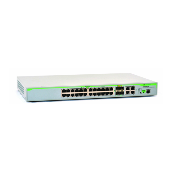
- Page 7 Figures Figure 1. AT-9000/28POE Switch............................16 Figure 2. AT-9000/12POE Switch Front and Rear Panels ....................20 Figure 3. AT-9000/28 Switch Front and Rear Panels ......................21 Figure 4. AT-9000/28POE Switch Front and Rear Panels ....................22 Figure 5. AT-9000/28SP Switch Front and Rear Panels .....................23 Figure 6.
- Page 8 Figures...
- Page 9 Table 3. Combo Ports .................................32 Table 4. System LED States ..............................37 Table 5. RJ-45 LINK LED States ............................38 Table 6. AT-9000/12POE RJ-45 PoE LED States ......................38 Table 7. RJ-45 Port LED MODE States ..........................39 Table 8. SFP LINK/ACT LED States ..........................40 Table 9.
- Page 10 Tables...
-
Page 11: Preface
This manual is the installation guide for the AT-9000 Gigabit Ethernet Switches. The switch models included in this series are: AT-9000/12POE AT-9000/28 AT-9000/28POE AT-9000/28SP AT-9000/52 This preface contains the following sections: “Document Conventions” on page 12 “Contacting Allied Telesis” on page 13 ... -
Page 12: Document Conventions
AT-9000 Gigabit Ethernet Switch Installation Guide Document Conventions This document uses the following conventions: Note Notes provide additional information. Caution Cautions inform you that performing or omitting a specific action may result in equipment damage or loss of data. Warning Warnings inform you that performing or omitting a specific action may result in bodily injury. -
Page 13: Contacting Allied Telesis
Preface Contacting Allied Telesis If you need assistance with this product, you may contact Allied Telesis technical support by going to the Support & Services section of the Allied Telesis web site at www.alliedtelesis.com/support. You can find links for the following services on this page: 24/7 Online Support —... - Page 14 AT-9000 Gigabit Ethernet Switch Installation Guide...
-
Page 15: Chapter 1: Overview
Chapter 1 Overview This chapter contains the following sections: “Switch Models and Features” on page 16 “AT-9000 Series Gigabit Ethernet Switches” on page 19 “10/100/1000Base-T Twisted-Pair Ports” on page 25 “Power Over Ethernet” on page 28 “SFP Slots”... -
Page 16: Switch Models And Features
AT-9000 Gigabit Ethernet Switch Installation Guide Switch Models and Features AT-9000 Series The AT-9000 series offers the following models: Models AT-9000/12POE AT-9000/28 AT-9000/28POE AT-9000/28SP AT-9000/52 The AT-9000 series switches are environmentally friendly Gigabit Ethernet (GE) switches, equipped with 10/100/1000 Mbps twisted-pair copper ports, 100/1000 Mbps SFP slots, and LEDs. -
Page 17: Power Over Ethernet
PoE and PoE+ supported on the 10/100/1000Base-TX ports on the AT-9000/12POE and AT-9000/28POE switches Powered device classes 0 to 4 Power budgets of 125 watts for the AT-9000/12POE switch and 370 watts for the AT-9000/28POE switch Port prioritization ... -
Page 18: Port Leds
AT-9000 Gigabit Ethernet Switch Installation Guide Port LEDs Here are the port LEDs: Duplex mode and link/activity LEDs for the twisted-pair ports PoE status for the twisted-pair ports on AT-9000/12POE and AT-9000/28POE switches Link/activity LEDs for the SFP slots ... -
Page 19: At-9000 Series Gigabit Ethernet Switches
Temperature-controlled fan Compliant with European and China RoHS standards AT-9000/12POE Features specific to the AT-9000/12POE switch include: Switch 12 port Gigabit Switch with 8 10/100/1000Base-T RJ-45 ports fixed configuration and 4 SFP/RJ-45 ports PoE and PoE+ supported on the 10/100/1000Base-TX ports ... -
Page 20: Figure 2. At-9000/12Poe Switch Front And Rear Panels
AT-9000 Gigabit Ethernet Switch Installation Guide ecoFriendly 10/100/1000 Button Base-T Ports Ports Console Port AC Power Connector Figure 2. AT-9000/12POE Switch Front and Rear Panels... -
Page 21: At-9000/28 Switch
Chapter 1: Overview AT-9000/28 Features specific to the AT-9000/28 switch include: Switch 28 port Gigabit Switch with 24 10/100/1000Base-T RJ-45 ports fixed configuration and 4 SFP/RJ-45 combo ports RJ-45 MODE LED selection button for status of collision, speed, duplex, or activity Figure 3 illustrates the front- and rear-panel features of the AT-9000/28 switch. -
Page 22: At-9000/28Poe Switch
AT-9000 Gigabit Ethernet Switch Installation Guide AT-9000/28POE Features specific to the AT-9000/28POE switch include: Switch 28 port Gigabit Switch with 24 10/100/1000Base-T RJ-45 ports fixed configuration and 4 SFP/RJ-45 combo ports PoE and PoE+ supported on the 10/100/1000Base-TX ports ... -
Page 23: At-9000/28Sp Switch
Chapter 1: Overview AT-9000/28SP Features specific to the AT-9000/28SP switch include: Switch 28 port Gigabit Switch with 24 Gigabit Ethernet small form-factor pluggable (SFP) transceiver slots and 4 SFP/RJ-45 combo ports RJ-45 MODE LED selection button for status of collision, speed, ... -
Page 24: At-9000/52 Switch
AT-9000 Gigabit Ethernet Switch Installation Guide AT-9000/52 Features specific to the AT-9000/52 switch include: Switch 52 port Gigabit Switch with 48 10/100/1000Base-T RJ-45 ports fixed configuration and 4 SFP slots RJ-45 MODE LED selection button for status of collision, speed, ... -
Page 25: 10/100/1000Base-T Twisted-Pair Ports
Chapter 1: Overview 10/100/1000Base-T Twisted-Pair Ports A twisted-pair cable port is shown in Figure 7. Figure 7. Twisted-Pair Cable Port See Figure 19 on page 83 for the pin layout to a port and RJ-45 connector. Speed The ports can operate at 10, 100, or 1000 Mbps. The speeds may be set manually using the management software or automatically with Autonegotiation (IEEE 802.3u), the default setting. -
Page 26: Wiring Configuration
The 10/100/1000Base-T ports on the AT-9000/28, AT-9000/28SP, and AT-9000/52 switches do not support PoE. Ethernet The AT-9000/12POE and AT-9000/28POE switches are equipped with PoE+ copper ports for a 10/100/1000BASE-T twisted-pair cable. Cable The cable requirements of the ports are given in Table 1 on page 27. -
Page 27: Port Pinouts
Chapter 1: Overview Table 1. Twisted-Pair Cable for the 10/100/1000Base-T Ports 10Mbps 100Mbps 1000Mbps Cable Type Non- Non- Non- PoE+ PoE+ PoE+ Standard TIA/EIA 568- B-compliant Category 3 shielded or unshielded cabling with 100 ohm impedance and a frequency of 16 MHz. Standard TIA/EIA 568- A-compliant Category 5 shielded or unshielded... -
Page 28: Power Over Ethernet
AT-9000 Gigabit Ethernet Switch Installation Guide Power Over Ethernet The AT-9000/12POE and AT-9000/28POE switches feature Power over Ethernet (PoE) on the 10/100/1000Base-TX ports. PoE is used to supply power to host devices over the same twisted-pair cables that carry the network traffic. -
Page 29: Powered Device Classes
12.95W to 25.5W Power Budget The AT-9000/12POE switch has a power budget of 125 watts. The AT-9000/28POE switch has a power budget of 370 watts. These are the maximum amounts of power the switches can provide at one time to the powered devices. -
Page 30: Port Prioritization
AT-9000 Gigabit Ethernet Switch Installation Guide The switch can handle different power requirements on different ports. This enables you to connect different classes of PoE equipment to the ports on the switch. Port If the power requirements of the powered devices exceed the switch’s power budget, the switch denies power to some ports based on a system Prioritization called port prioritization. -
Page 31: Wiring Implementation
100Base-TX devices that carry the network data. With Mode B, the power is provided over the spare strands. The ports on the AT-9000/12POE and AT-9000/28POE switches deliver the power using pins 4, 5, 7, and 8, which corresponds to Mode B in the IEEE 802.3af standard. -
Page 32: Sfp Slots
The switches support a variety of short and long distance, 100 and 1000 Mbps fiber optic SFP modules. For a list of supported SFP modules, contact your Allied Telesis representative or visit our website. On the AT-9000/28, AT-9000/28POE, and AT-9000/28SP switches, the four SFP slots are paired with the four 10/100/1000Base-T ports. - Page 33 Chapter 1: Overview Port speed is an exception to the shared settings of the twisted-pair port and SFP slot of a combo port. If you disable Autonegotiation on the twisted-pair port (and set the speed and duplex mode manually), the switch will reactivate Autonegotiation when an SFP module establishes a link with an end node.
-
Page 34: Combo Ports
AT-9000 Gigabit Ethernet Switch Installation Guide Combo Ports The AT-9000/28, AT-9000/28POE, and AT-9000/28SP switches have four combo pairs of uplink ports, each consisting of one slot for an SFP transceiver and a redundant 10/100/1000 Base-T twisted-pair port. These combo ports are numbered 25 through 28 on the switches. The twisted- pair ports in each of the combo pairs are identified with the letter “R”... - Page 35 Chapter 1: Overview Note For a list of supported SFP transceivers for the AT-9000 Series Managed Layer 2 Gigabit Ethernet Switches, contact your Allied Telesis sales representative.
-
Page 36: Console Port
AT-9000 Gigabit Ethernet Switch Installation Guide Console Port The Console port is used to configure the features and parameter settings of the switch. This type of management uses serial RS-232 and is commonly referred to as local or out-of-band management because it is not conducted over your network. -
Page 37: Leds
Figure 9. RJ-45 Port LEDs On each port, the left LED indicates the Link status. Depending on the switch, the right LED indicates the status as follows: AT-9000/12POE: PoE. The AT-9000/12POE does not have a MODE LED SELECT button. -
Page 38: Table 5. Rj-45 Link Led States
AT-9000/12POE Flashing Port is transmitting or receiving Green data PoE LED On the AT-9000/12POE switch, the right LED indicates the PoE status as described in Table 6. Table 6. AT-9000/12POE RJ-45 PoE LED States LED State Description Solid Green PoE is enabled... -
Page 39: Figure 10. Front Panel Mode Led Select Button And Leds
Chapter 1: Overview is indicated on one of the LEDs next to the MODE LED SELECT button, as shown in Figure 10. Figure 10. Front Panel MODE LED SELECT Button and LEDs The RJ-45 Port MODE LED states are described in Table 7. Each port MODE is selected by the MODE SELECT button. -
Page 40: Sfp Leds
AT-9000 Gigabit Ethernet Switch Installation Guide SFP LEDs Each SFP slot has one SFP LINK/ACT LED. An up-arrow LED corresponds to the upper SFP slot, and a down-arrow LED corresponds to the lower SFP slot. The SFP LINK/ACT LEDs are illustrated in Figure 11, and their function is described in Table 8: LINK/ACT LEDs Figure 11. -
Page 41: Ecofriendly Button
Chapter 1: Overview ecoFriendly Button The ecoFriendly button enables the Low Power Mode (LPM) feature. This mode allows you to conserve power by turning off the port and MODE LEDs when they are not required. To toggle the LEDs on or off, press the ecoFriendly button, located on the front panel of the switch. -
Page 42: Power Supplies
AT-9000 Gigabit Ethernet Switch Installation Guide Power Supplies The AT-9000/12POE, AT-9000/28, AT-9000/28SP, and AT-9000/52 switches have one AC power supply. The AT-9000/28POE switch has two AC power supplies. The supplies are not field-replaceable. Excluding PoE operation, only one power supply is active at a time in the AT-9000/28POE switch. -
Page 43: Power Connectors
Chapter 1: Overview Power Connectors The AT-9000/12POE, AT-9000/28, AT-9000/28SP, and AT-9000/52 switches have one AC power supply socket on the back panel. The AT-9000/28POE switch has two AC power supply sockets. AC switches are powered on or off by connecting or disconnecting the... - Page 44 AT-9000 Gigabit Ethernet Switch Installation Guide...
-
Page 45: Chapter 2: Beginning The Installation
Chapter 2 Beginning the Installation This chapter contains the following sections: “Installation Procedures” on page 46 “Reviewing Safety Precautions” on page 47 “Selecting a Site” on page 51 “Unpacking the Switch” on page 52 ... -
Page 46: Installation Procedures
AT-9000 Gigabit Ethernet Switch Installation Guide Installation Procedures You may install the switch on a table or desktop, or in an equipment rack. To install the switch on a table or desktop, refer to “Installing the Switch on a Table or Desktop” on page 54. To install the switch in an equipment rack, refer to “Installing the ... -
Page 47: Reviewing Safety Precautions
Note indicates that a translation of the safety statement is available in a PDF document titled “Translated Safety Statements” posted on the Allied Telesis website at http:// www.alliedtelesis.com/support. Note Refer to the data sheet about an SFP module at www.alliedtelesis.com to determine whether it is a Class 1 LED or... - Page 48 AT-9000 Gigabit Ethernet Switch Installation Guide Warning Do not work on equipment or cables during periods of lightning activity. Warning Power cord is used as a disconnection device. To de-energize equipment, disconnect the power cord. Warning Class I Equipment. This equipment must be earthed. The power plug must be connected to a properly wired earth-ground socket outlet.
- Page 49 Chapter 2: Beginning the Installation Warning Only trained and qualified personnel are allowed to install or replace this equipment. Caution Circuit Overloading: Consideration should be given to the connection of the equipment to the supply circuit and the effect that overloading of circuits might have on over-current protection and supply wiring.
- Page 50 AT-9000 Gigabit Ethernet Switch Installation Guide Caution Installation of the equipment in a rack should be such that the amount of air flow required for safe operation of the equipment is not compromised. Warning Reliable earthing of rack-mounted equipment should be maintained. Particular attention should be given to supply connections other than direct connections to the branch circuits (for example, use of power strips).
-
Page 51: Selecting A Site
Chapter 2: Beginning the Installation Selecting a Site Observe the following requirements when choosing a site for the switch: If you plan to install the switch in an equipment rack, check that the rack is safely secured and will not tip over. Devices in a rack should be installed starting at the bottom, with the heavier devices near the bottom of the rack. -
Page 52: Unpacking The Switch
Telesis sales representative for assistance. One AT-9000 Managed Layer 2 GE ecoSwitch Mounting brackets: AT-9000/12POE: two brackets - one long bracket and one short bracket AT-9000/28, AT-9000/28POE, AT-9000/28SP, AT-9000/52: two brackets Eight flathead Phillips rack-mount bracket screws ... -
Page 53: Chapter 3: Installing The Switch On A Table Or Rack
Chapter 3 Installing the Switch on a Table or Rack This chapter contains the following sections: “Installing the Switch on a Table or Desktop” on page 54 “Installing the Switch in a Rack” on page 55 ... -
Page 54: Installing The Switch On A Table Or Desktop
AT-9000 Gigabit Ethernet Switch Installation Guide Installing the Switch on a Table or Desktop You may install the switch on a table or desktop. Here are the guidelines for selecting a site: The table should be level and stable. The power outlet should be located near the switch and be easily ... -
Page 55: Installing The Switch In A Rack
Installing the Switch in a Rack Installation guidelines may be found in “Selecting a Site” on page 51. Caution The chassis may be heavy and awkward to lift. Allied Telesis recommends that you get assistance when mounting the chassis in an equipment rack. -
Page 56: Figure 14. Attaching Brackets For Rack Mounting
AT-9000 Gigabit Ethernet Switch Installation Guide Figure 14. Attaching Brackets for Rack Mounting Figure 15. Attaching Brackets for Rack Mounting (Continued) 5. Install the second mounting bracket on the other side of the switch using the four remaining screws. -
Page 57: Figure 16. Mounting The Switch In A Rack
Chapter 3: Installing the Switch on a Table or Rack 6. Mount the switch in the 19-inch rack using standard screws (not provided), as shown in Figure 16. Figure 16. Mounting the Switch in a Rack... - Page 58 AT-9000 Gigabit Ethernet Switch Installation Guide...
-
Page 59: Chapter 4: Cabling The Networking Ports
Chapter 4 Cabling the Networking Ports Observe the following guidelines when connecting a twisted-pair cable to a port on the switch: The cable specifications for the 10/100/1000Base-T twisted pair ports are listed in Table 1 on page 27. The connector on the cable should fit snugly into the port on the ... - Page 60 AT-9000 Gigabit Ethernet Switch Installation Guide The default speed setting for the ports is Autonegotiation. This setting is appropriate for ports connected to host devices that also support Autonegotiation. The default speed setting of Autonegotiation is not appropriate for ...
-
Page 61: Chapter 5: Powering On The Switch
Chapter 5 Powering On the Switch This chapter contains the following sections: “Applying AC Power” on page 62 “Starting a Local Management Session” on page 64 “Management Methods” on page 66 “Adding a Management IP Address” on page 69 ... -
Page 62: Applying Ac Power
AT-9000 Gigabit Ethernet Switch Installation Guide Applying AC Power Consider the following items as you power on the switch: All of the models have one power supply, except for the AT-9000/ 28POE switch, which has two power supplies with separate connectors. - Page 63 Chapter 5: Powering On the Switch 2. Connect the other end of the power cord to an appropriate AC power outlet. For power specifications for the switch, refer to “Power Specifications” on page 81. 3. When power is applied, the switch begins to load the Management Software.
-
Page 64: Starting A Local Management Session
1. Connect the RJ-45 end of the management cable, included with the shipping package, to the Console port. The Console port is located on the front panel of the AT-9000/12POE, AT-9000/28, AT-9000/28POE, and AT-9000/28SP switches, as shown in Figure 18, and on the rear panel of the AT-9000/52 switch. - Page 65 Chapter 5: Powering On the Switch 4. Press Enter. You are prompted for a user name and password. 5. To configure the switch settings, enter “manager” as the user name. The default password for manager access is “friend.” User names and passwords are case sensitive.
-
Page 66: Management Methods
AT-9000 Gigabit Ethernet Switch Installation Guide Management Methods You may use the following methods and tools to manage AT-9000 series switches: Local management Telnet client Secure Shell (SSH) client HTTP non-secure and HTTPs secure web browser SNMPv1, v2c, v3 ... -
Page 67: Secure Shell Management
Chapter 5: Powering On the Switch Secure Shell Secure Shell (SSH) management is similar to Telnet management in that you may use it, together with the command line interface, to manage all of Management the features and functions of the switch, from a workstation on your network. -
Page 68: Snmp
AT-9000 Gigabit Ethernet Switch Installation Guide SNMP Refer to the AT-9000 Series Management Command Line Interface User’s Guide for instructions on how to configure the switch for SNMP management. The switch does not have any default SNMP community strings. -
Page 69: Adding A Management Ip Address
Chapter 5: Powering On the Switch Adding a Management IP Address You must assign the switch a management IP address to access the web user interface and to remotely manage the switch during a remote Telnet connection. Here are the requirements: The switch can have one management IPv4 address and one ... -
Page 70: Table 9. Example Of Adding A Management Address
AT-9000 Gigabit Ethernet Switch Installation Guide Table 9. Example of Adding a Management Address Move to the Privileged Exec mode. awplus> enable Move to the Global Configuration mode. awplus# configure terminal Use the INTERFACE VLAN command to move to the awplus(config)# interface vlan1 VLAN Interface mode of the Default VLAN. -
Page 71: Chapter 6: Troubleshooting
Note If you are unable to resolve a problem after following the instructions in this chapter, contact Allied Telesis Technical Support for assistance. Refer to “Contacting Allied Telesis” on page 13 for contact information. This chapter contains the following sections: “Power LED Is Off”... -
Page 72: Power Led Is Off
AT-9000 Gigabit Ethernet Switch Installation Guide Power LED Is Off Check the PWR LED on the front of the switch. If the LED is off, indicating that the unit is not receiving power, do the following: Make sure the power cord is securely connected to the power ... -
Page 73: Twisted-Pair Port Link Led Is Off
Chapter 6: Troubleshooting Twisted-Pair Port Link LED Is Off When a twisted-pair port on the switch is connected to a properly operating end node, the Link LED for the port should be on. If a Link LED is off, do the following: Verify that the switch is not set to the power-saving mode by ... -
Page 74: Cannot Establish A Local (Out-Of-Band) Management Session
AT-9000 Gigabit Ethernet Switch Installation Guide Cannot Establish a Local (Out-of-Band) Management Session If you are unable to establish a local (out-of-band) management session with the switch through the terminal port on the front panel, do the following: Check that the RJ-45 connector of the serial management cable is ... -
Page 75: All Port Leds Are Off
Chapter 6: Troubleshooting All Port LEDs Are Off If all of the port LEDs are off, even though the ports are connected to active host devices, the switch may be operating in the low-power mode. To toggle on the LEDs, press the ecoFriendly button on the front panel of the switch. -
Page 76: Power Over Ethernet
AT-9000 Gigabit Ethernet Switch Installation Guide Power Over Ethernet This section applies only to the AT-9000/12POE and AT-9000/28POE switches. Each RJ-45 port switch has two LEDs. The left LED provides port link and activity status, and the right LED provides PoE status information. The PoE LED is solid green when PoE is enabled. -
Page 77: Fiber Optic Transceivers
Chapter 6: Troubleshooting Fiber Optic Transceivers This section applies only to the AT-9000/12POE, AT-9000/28, AT-9000/ 28POE, and AT-9000/28SP switches. The SFP LINK/ACT LEDs on the SFP ports are solid or flashing green when the fiber optic transceivers have links to end nodes. If a transceiver... -
Page 78: Slow Performance Between Switch And Host Device
AT-9000 Gigabit Ethernet Switch Installation Guide Slow Performance Between Switch and Host Device If network performance between a twisted-pair port on the switch and a host device is slow, there might be a duplex mode mismatch between the port and the host device. This occurs when a twisted-pair port using Autonegotiation is connected to a device with a fixed duplex mode of full duplex. -
Page 79: Appendix A: Technical Specifications
Physical Specifications and Power Specifications. Physical Specifications Dimensions (W x D x H) Table 10. Product Dimensions AT-9000/12POE 33 cm x 20.3 cm x 4.4 cm (13 in. x 8 in. x 1.73 in.) AT-9000/28 44 cm x 25.6 cm x 4.4 cm AT-9000/28SP (17.33 in. -
Page 80: Table 11. Product Weights
AT-9000 Gigabit Ethernet Switch Installation Guide Weights Table 11. Product Weights AT-9000/12POE 2.40 kg (5.3 lb.) AT-9000/28 3.62kg (8.00 lb.) AT-9000/28SP 3.95 kg (8.70 lb.) AT-9000/28POE 5.22 kg (11.5 lb.) AT-9000/52 4.06 kg (8.85 lb.) Ventilation Requirements Recommended minimum ventilation on all sides: 10 cm (4.0 in.) -
Page 81: Environmental Specifications
Operating Altitude Range Up to 2,000 m (6,562 ft.) Acoustic Noise 75.7 dB Power Specifications AC Power Consumption Table 13. AC Power Consumption AT-9000/12POE 160 watts maximum AT-9000/28 33 watts maximum AT-9000/28SP 44 watts maximum AT-9000/28POE 241 watts per input maximum... -
Page 82: Safety And Electromagnetic Emissions Certifications
AT-9000 Gigabit Ethernet Switch Installation Guide Safety and Electromagnetic Emissions Certifications FCC Class A, CISPR 22 Class A, EN55022 Class A, C-TICK Immunity EN55024, EN61000-3-2, EN61000-3-3 Safety UL 60950-1 ( EN60950-1 (TUV) Quality and Reliability MTBF – 340,000 hours Compliance Standards IEEE 802.3 –... -
Page 83: 10/100/1000Base-T Twisted-Pair Port Connectors
Appendix A: Technical Specifications 10/100/1000Base-T Twisted-Pair Port Connectors This section lists the pin signals for the 10/100/1000Base-T twisted-pair ports. Figure 19 illustrates the pin layout to an RJ-45 connector and port. Figure 19. RJ-45 Connector and Port Pin Layout Table 15 lists the RJ-45 pin signals when a twisted-pair port is operating in the MDI configuration. -
Page 84: Console Port Pinouts
AT-9000 Gigabit Ethernet Switch Installation Guide Table 17 lists the RJ-45 connector pins and their signals when a 1000Base-T port is operating at 1000 Mbps. Table 17. RJ-45 1000Base-T Connector Pinouts Pair Signal TX and RX+ TX and RX- TX and RX+ TX and RX+ TX and RX- TX and RX-...
Need help?
Do you have a question about the AT-9000/12PoE and is the answer not in the manual?
Questions and answers