
Related Manuals for VIA Technologies VB8001-16 - VIA Motherboard - Mini ITX


Summary of Contents for VIA Technologies VB8001-16 - VIA Motherboard - Mini ITX
- Page 1 User’s Manual VIA EPIA-V Mini-ITX Mainboard Version 1.2 December, 2003 P/N 99-51-012551-12...
- Page 2 Copyright Copyright by VIA Technologies Inc. (“VIA”). No part of this manual may be reproduced or transmitted in any form without express written authorization from VIA. Trademarks All trademarks are the property of their respective holders. Data protection All data should be backed-up prior to the installation of any drive unit or storage peripheral.
- Page 3 FCC-B Radio Frequency Interference Statement This equipment has been tested and found to comply with the limits for a class B digital device, pursuant to part 15 of the FCC rules. These limits are designed to provide reasonable protection against harmful interference when the equipment is operated in a commercial environment.
-
Page 4: Copyright Notice
Copyright Notice We take every care in the preparation of this document, but no guaran- tee is given as to the correctness of its contents. Our products are under continual improvement and we reserve the right to make changes without notice. Trademarks All trademarks used in this manual are the property of their respective owners. -
Page 5: Safety Instructions
Safety Instructions NOTE 1. Always read the safety instructions carefully. 2. Keep this User’s Manual for future reference. 3. Keep this equipment away from humidity. 4. Lay this equipment on a reliable flat surface before setting it up. 5. The openings on the enclosure are for air convection hence pro- tects the equipment from overheating. - Page 6 Box Contents This VIA EPIA-V Mini-ITX Mainboard package should contain the follow- ing items: • 1 x VIA EPIA-V Mini-ITX Mainboard • 1 x User’s manual • 1 x ATA-33/66/100 Hard drive ribbon cable • 1 x Floppy ribbon cable •...
-
Page 7: Table Of Contents
Contents Specifications ............1-1 Mainboard Specifications..........1-2 Mainboard Layout............1-4 Connectors Guide ............1-5 Installation ............. 2-1 CPU ................. 2-2 The VIA C3™ E-Series Processor ........2-2 The VIA Eden Processor ..........2-3 Memory Installation ............2-4 SDRAM Module Installation Procedures ......2-4 Available SDRAM Configurations ........ - Page 8 Video In Connector (J12) ..........2-14 Floppy Disk Drive Connector: FDD ....... 2-14 Jumpers................2-15 Clear CMOS Jumper: CLEAR_CMOS ......2-15 Host Frequency Select (J13) ........... 2-16 Auto Reboot Function Setting (J2) ........2-17 RCA Video or S/PDIF Select (J11) ......... 2-17 Slots................
- Page 9 Software Setup ............4-1 Driver Utilities CD Content ..........4-2 Getting Started ..............4-2 Running the Driver Utilities CD ........4-2 CD Content ..............4-2 viii...
-
Page 10: Specifications
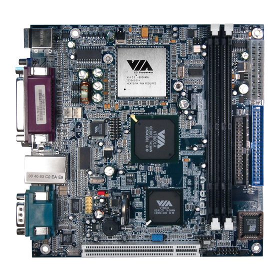
Specifications Specifications The ultra-compact and highly intergrated VIA EPIA-V Mini-ITX Mainboard is the smallest form factor mainboard specification available today, developed by VIA Technologies, Inc as part of the company’s open industry- wide Total Connectivity initiative. The VIA EPIA-V Mini- ITX mainboard enables the creation of an exciting new generation of small, ergonomic, innovative and affordable embedded systems. -
Page 11: Main Memory
Chapter 1 Specifications • Embeddeed VIA Processor • Enhanced Ball Grid Array Package (EBGA) • Internal L1 128KB and L2 64KB cache memory Chipset • VIA 8601A North Bridge • VT8231 South Bridge Graphics • Integrated Trident Blade 3D graphics core Audio •... -
Page 12: Form Factor
Specifications Onboard I/O Connectors • 1 USB connector for 2 USB 1.1 ports • CD Audio-in connector • FIR connector • PS2 connector • Wake-on-Modem • CPU/Sys FAN Back Panel I/O • 1 PS2 mouse port • 1 PS2 keyboard port •... -
Page 13: Com Port
Chapter 1 Layout PS / 2 Line Line Video CRT Connector S-Video USB 0 Keyboard S/PDIF USB 1 COM Port LPT Connector Mouse RCA Video RJ45 S/PDIF VT1612A FAN 1 FAN 2 F_USB TV Out VT6103 CD-ROM Line-In VT1621 Clear CMOS Wake up On Modem Buzzer Battery CR2032... -
Page 14: Connectors Guide
Specifications Connectors Guide Component Function Reference Fan 1, Fan 2 Fan power connectors See p. 2-2 DIMM1, DIMM2 DIMM slot See p. 2-4 ATX Power Connector Connecting ATX power supply See p. 2-6 PS/2 Mouse Mouse connector See p. 2-7 PS/2 Keyboard Keyboard connector See p. -
Page 15: Installation
Hardware Setup Installation This chapter provides you with the information about hardware setup procedures. While installating, please be careful in holding the components and follow the installation procedures. Some components could be damaged if they are installed incorrectly. If possible, use a grounded wrist strap before handling computer components. -
Page 16: Cpu
Chapter 2 The VIA EPIA-V Mini-ITX Mainboard includes an embedded VIA Eden Proc- essor or VIA C3™ E-Series Processor. Two fan connectors (Fan 1 & Fan 2) are provided on the mainboard, allowing for the connection of a CPU fan and an additional system case fan. -
Page 17: The Via Eden Processor
Hardware Setup The VIA Eden Processor Providing ultra-low power consumption and advanced thermal dissipation properties, the VIA Eden Processor features a fanless design. The VIA Eden Processor requires only a heatsink, as shown below. CPU Heatsink Overclocking This motherboard is not designed to support overclocking. -
Page 18: Memory Installation
Chapter 2 Memory Installation The VIA EPIA-V Mini-ITX Mainboard provides two 168-pin DIMM slots for PC 100/133 SDRAM memory modules. To operate properly, at least one module must be installed. DIMM 1 & DIMM 2 SDRAM Module Installation Procedures 1.) Push the white retaining latches at either end of the DIMM slot outwards. 2.) Align the SDRAM module with the corresponding notches on the DIMM slot. -
Page 19: Available Sdram Configurations
Hardware Setup Available SDRAM Configurations Refer to the table below for available SDRAM configurations on the VIA EPIA-V Mini-ITX Mainboard. Socket M em ory M odule Total M em ory DIMM 1 32M B, 64M B, 128MB, 32M B~512MB 256M B, 512MB DIMM 2 32M B, 64M B, 128MB, 32M B~512MB... -
Page 20: Power Supply
Chapter 2 Power Supply The VIA EPIA-V Mini-ITX Mainboard requires an ATX power supply to be connected. Before inserting the power supply connector, always make sure that all components are installed correctly to ensure that no damage will be caused. ATX 20-Pin Power Connector To connect the ATX power supply, make sure the plugs of the power supply are inserted in the proper orientation and the pins are correctly aligned. -
Page 21: Back Panel
Hardware Setup Back Panel The back panel of the VIA EPIA-V Mini-ITX Mainboard contains the follow- ing connectors: PS/2 Mouse LPT Connector RJ-45 Port COM Port S-Video Port PS/2 Keyboard USB Ports Line Line CRT Connector RCA Video (Audio Connectors) S / P DIF Port Keyboard Connector: JKB1 Mouse Connector: JMS1... -
Page 22: Usb Port Connectors
Chapter 2 USB Port Connectors The mainboard provides 2 USB 1.1 ports (plus 1 pin-headers for up to 2 additional USB connections). USB-compatible devices can be plugged di- rectly into these ports. Pin Definition 5 6 7 8 SIGNAL DESCRIPTION -Data 0 Negative Data Channel 0 +Data 0... -
Page 23: Serial Port Connector: Com 1
Hardware Setup Serial Port Connectors: COM 1 The mainboard offers one 9-pin male Serial Port connector (COM 1) . You can attach a serial mouse or other serial devices directly to this port. Pin Definition 1 2 3 4 5 SIGNAL DESCRIPTION Data Carry Detect... -
Page 24: Connectors
Chapter 2 Connectors The VIA EPIA-V Mini-ITX Mainboard provides the following connectors: Hard Disk Connectors: IDE1 The mainboard has a 32-bit Enhanced PCI IDE and Ultra DMA 33/66/100 controller that provides PIO mode 0~4, Bus Master, and Ultra DMA 33/66/ 100 functions. -
Page 25: Front Panel Connector (J3)
Hardware Setup Front Panel Connector (J3) The J3 front panel connectors allow you to connect the Power Switch, Reset Switch, Power LED and HDD LED to the system case. HDD LED Power LED Power Switch Reset CD-ROM Line In Connector (J7) The J7 internal CD-ROM Line In Connector allows you to connect and re- ceive audio input from a device such as a CD-ROM. -
Page 26: Fir Module Connector (J5)
Chapter 2 FIR Module Connector (J5) The FIR Module Connector (J5) allows you to connect a Fast Infrared stan- dard module. You must configure the setting through the BIOS setup to acti- vate the IR function. Pin Definition SIGNAL IRRX IRRX2 IRTX PS2 Connector (J6) -
Page 27: Wake On Modem Connector (J8)
Hardware Setup Wake On Modem Connector (J8) This connector (J8) allows you to connect to a modem with the Wake On Modem function. The connector will power up the system when a signal is received through the modem. +5V_SB USB Port 2&3 Connector (F_USB) This connector allows you to connect an additional two Universal Serial Bus (USB) ports, in case the two USB ports on the back panel are not sufficient. -
Page 28: Video In Connector (J12)
Chapter 2 Video In Connector (J12) The Video In Connector allows you to connect an external video source. SIGNAL SIGNAL CVD0 CVD7 CVD4 CVD6 CVD5 CVHS CVD2 CVD1 CVD3 CVVS CVCLK A_D30 -GNT2 -REQ2 Floppy Disk Drive Connector: FDD The standard floppy disk drive connector supports 360K, 720K, 1.2M, 1. 44M, and 2.88M. -
Page 29: Jumpers
Hardware Setup Jumpers The Mainboard provides a series of jumpers to set the computer’s functions. This section explains how to change settings for your mainboard’s functions through the use of the jumpers. Clear CMOS Jumper: CLEAR_CMOS (J10) The onboard CMOS RAM stores system configuration data and has an onboard battery power supply. -
Page 30: Host Frequency Select (J13)
Chapter 2 Host Frequency Select (J13) This jumper can be used to select the host frequency bus speed of the mainboard. The three available options are 66MHz, 100MHz and 133MHz. J13 Host Frequency Select Overclocking WARNING! This motherboard is not designed to support overclocking. -
Page 31: Auto Reboot Function Setting (J2)
Hardware Setup Auto Reboot Function Setting (J2) This jumper enables or disables the Auto Reboot Function Setting. When enabled, the system will automatically reboot in the event it of sudden power outage. 1-2: Disable 2-3: Enable RCA Video or S/PDIF Select (J11) Users can select either RCA Video or S/PDIF as the enabled function on the dual-purpose port. -
Page 32: Slots
Chapter 2 Slots PCI Slot The PCI slot allows you to insert PCI expansion card. When adding or re- moving expansion cards, make sure that you unplug the power supply first. Meanwhile, read the documentation for the expansion card to make any nec- essary hardware or software settings for the expansion card, such as jumpers, switches or BIOS configuration. -
Page 33: Pci Interrupt Request Routing
Hardware Setup PCI Interrupt Request Routing PCI Interrupt Request Routing The IRQ (Interrupt ReQuest) is the mechanism for devices to request ser- vices from the microprocessor. The “PCI & LAN” IRQ pins are typically connected to the PCI bus INT A# ~ INT D# pins as follows: Order 1 Order 2 Order 3... -
Page 34: Bios Setup
BIOS Setup BIOS Setup This chapter gives you detailed explaination of BIOS setup functions. It consists of the following topics: Entering Setup Control Keys Getting Help The Main Menu Standard CMOS Features Advanced BIOS Features Advanced Chipset Features 3-11 Integrated Peripherals 3-13 Power Management Setup 3-16... -
Page 35: Entering Setup
Chapter 3 Entering Setup Power on the computer and press DEL straight away to enter the BIOS setup menu. If you missed the BIOS setup entry point, you may restart the system and try again. Control Keys Move to the previous item <... -
Page 36: Getting Help
BIOS Setup Getting Help After entering the BIOS setup menu, the Main Menu appears. Main Menu The main menu displays all BIOS setup categories. Use the control keys ( ) to select any item/sub-menu. Description of the selected/highlighted category is displayed at the bottom of the screen. -
Page 37: The Main Menu
Chapter 3 The Main Menu The Main Menu contains twelve setup functions and two exit choices. Use arrow keys to select the items and press <Enter> to accept or enter the sub- menu. Standard CMOS Features Use this menu to set basic system configurations. Advanced BIOS Features Use this menu to set the advanced features available on your system. - Page 38 BIOS Setup PC Health Status This menu shows the PC health status. Frequency/Voltage Control Use this menu to set the system frequency and voltage control. Load Fail-Safe Defaults Use this menu to load the BIOS default settings for minimal and stable system operations.
-
Page 39: Standard Cmos Features
Chapter 3 Standard CMOS Features Use the arrow keys to highlight the item and use the <PgUp> or <PgDn> keys to select the value you desire for each item. Date The date format is <Day><Month><Date><Year>. Day - day of the week, for example Friday. Read-only. Month - the month from Jan to Dec. - Page 40 BIOS Setup IDE Primary Master/Slave Press <Enter> to enter the sub-menu and the following screen appears: The specifications of your drive must match with the drive table. The hard disk will not work properly if you enter improper information for this category. Select Auto whenever possible.
-
Page 41: Advanced Bios Features
Chapter 3 Advanced BIOS Features Virus Warning Set the Virus Warning feature for IDE Hard Disk boot sector protection. If the function is enabled, any attempt to write data into this area will cause a beep and a warning message will be displayed. Settings: Disabled and Enabled. CPU L2 Cache ECC Checking Set the ECC (Error-Correcting Code) feature for Level 2 cache. - Page 42 BIOS Setup Floppy The system will boot from floppy drive. LS120 The system will boot from LS-120 drive. HDD-0 The system will boot from first HDD. SCSI The system will boot from SCSI. CD-ROM The system will boot from CD-ROM. HDD-1 The system will boot from second HDD.
-
Page 43: Security Option
Chapter 3 Typematic Rate Setting Set the typematic rate and delay. Settings: Enabled and Disabled. Typematic Rate (Chars/Sec) When Typematic Rate Setting is enabled. This item allows you to set the rate (characters/second) at which the keys are accelerated. Settings: 6, 8, 10, 12, 15, 20, 24 and 30. -
Page 44: Advanced Chipset Features
BIOS Setup Advanced Chipset Features The Advanced Chipset Features menu is used for optimizing the chipset functions. Note: Change these settings only if you are familiar with the chipset. AGP Aperture Size This setting controls how much memory space can be allocated to AGP for display purposes. - Page 45 Chapter 3 P2C/C2P Concurrency The settings are Enabled and Disabled. Fast R-W Turn Around The settings are Enabled and Disabled. PCI Dynamic Bursting The settings are Enabled and Disabled. PCI#2 Access #1 Retry The settings are Enabled and Disabled. CPU to PCI POST Write When Enabled, CPU can write up to four words of data to the PCI write buffer before CPU must wait for PCI bus cycle to finish.
-
Page 46: Integrated Peripherals
BIOS Setup Integrated Peripherals Onboard IDE Channel The integrated peripheral controller contains an IDE interface. Choose Enabled to activate the channel. Settings: Disabled, Enabled. IDE Prefetch Mode This allows your hard disk controller to use the fast block mode to trans- fer data to and from the hard disk drive. - Page 47 Chapter 3 AC97 Audio Auto allows the mainboard to detect whether an audio device is used. If the device is detected, the onboard VIA AC’97 (Audio Codec’97) con- troller will be enabled; if not, it is disabled. Disable the controller if you want to use other controller cards to connect an audio device.
- Page 48 BIOS Setup VIA SuperIO Device Press <Enter> to enter the sub-menu and the following screen appears: Onboard FDD Controller Enable the onboard floppy controller. Select “Enabled” when you have installed a floppy disk drive. Settings: Enabled and Disabled. Onboard Serial Port 1 Set the base I/O port address and IRQ for the onboard serial port A/serial port B.
-
Page 49: Power Management Setup
Chapter 3 Power Management Setup The Power Management Setup menu configures the system to most effec- tively save energy while operating in a manner consistent with your own style of computer use. ACPI Function Activate the ACPI (Advanced Configuration and Power Management Interface) Function. -
Page 50: Pm Control By Apm
BIOS Setup Set the idle time before system enters power saving mode. ACPI OS such as Windows XP will override this option. Settings: Disable and 1/ 2/4/6/8/10/20/30/40 min and 1 hr. ACPI Suspend Type Set the power saving mode for ACPI function. Settings are: S1/POS - S1/Power On Suspend (POS) is a low power state. -
Page 51: Peripheral Activities
Chapter 3 Peripheral Activities Press <Enter> to enter the sub-menu and the following screen appears: VGA Event Decide whether or not the power management unit should monitor VGA activities. Settings: Off and ON. LPT & COM Event Decide whether or not the power management unit should monitor parallel port (LPT) and serial port (COM) activities. - Page 52 BIOS Setup PS2KB Wakeup from suspend Select which “Hot-Key” is used to wake-up the system from power saving mode. Settings: Disabled, Ctrl+F1, Ctrl+F2, Ctrl+F3, Ctrl+F4, Ctrl+F5, Ctrl+F6, Ctrl+F7, Ctrl+F8, Ctrl+F9, Ctrl+F10, Ctrl+F11, Ctrl+F12, Power, Wake and Any Key. USB Resume Decide whether or not the USB devices can wake the system from suspend state.
-
Page 53: Irqs Activities
Chapter 3 IRQs Activities Press <Enter> to enter the sub-menu and the following screen appears: Primary INTR Selecting ON will cause the system to wake up from power saving modes if activity is detected from any enabled IRQ channels. Settings: OFF and IRQ3~IRQ15 Enables or disables the monitoring of the specified IRQ line. -
Page 54: Pnp/Pci Configurations
BIOS Setup PNP/PCI Configurations This section describes the BIOS configuration of the PCI bus system. This section covers some very technical items and it is strongly recommended that only experienced users should make any changes to the default settings. PNP OS Installed When set to Yes, BIOS will only initialize the PnP cards used for booting (VGA, IDE, SCSI). - Page 55 Chapter 3 IRQ Resources The items are adjustable only when Resources Controlled By is set to Manual. Press <Enter> and you will enter the sub-menu of the items. IRQ Resources list IRQ 3/4/5/7/9/10/11/12/14/15 for users to set each IRQ a type depending on the type of device using the IRQ. Settings: PCI Device For Plug &...
-
Page 56: Pc Health Status
BIOS Setup PC Health Status This section shows the status of your CPU, fan, warning for overall system status. Current CPU Temp, CPU Fan Speed, System Fan Speed, +12V, +5V, +3.3V, CPU Vcore. These items display the current status of all of the monitored hardware devices/components such as CPU voltages, temperatures and all fans’... -
Page 57: Frequency/Voltage Control
Chapter 3 Frequency/Voltage Control DRAM Clock The chipset supports synchronous and asynchronous mode between host clock and DRAM clock frequency. Settings: Host CLK, HCLK-33M, HCLK+33M, and By Auto. DRAM Timing By SPD This setting determines whether DRAM timing is configured by reading the contents of the SPD (Serial Presence Detect) EPROM on the DRAM module. -
Page 58: Load Fail-Safe Defaults
BIOS Setup Load Fail-Safe Defaults This option on the main menu allows users to restore all the BIOS settings to the default Fail Safe values. These values are set by the mainboard manufac- turer to provide the most stable system. When you select Load-Fail Safe Defaults, a message as below appears: Pressing ‘Y’... -
Page 59: Load Optimized Defaults
Chapter 3 Load Optimized Defaults This option on the main menu allows users to restore all the BIOS settings to the default Optimized values. The Optimized Defaults are the default values also set by the mainboard manufacturer for both optimized and stable perform- ance of the mainboard. -
Page 60: Set Supervisor/User Password
BIOS Setup Set Supervisor/User Password When you select this function, a message as below will appear on the screen: Type the password, up to eight characters in length, and press <Enter>. The password typed now will clear any previously set password from CMOS memory. - Page 61 Chapter 3 About Supervisor Password & User Password: Supervisor password : Can enter and change the settings of the setup menus. User password: Can only enter but do not have the right to change the settings of the setup menus. 3-28...
-
Page 62: Save & Exit Setup
BIOS Setup Save & Exit Setup When you want to quit the Setup menu, you can select this option to save the changes and quit. A message as below will appear on the screen: Typing “Y” will allow you to quit the Setup Utility and save the user setup changes to RTC CMOS. -
Page 63: Exit Without Saving
Chapter 3 Exit Without Saving When you want to quit the Setup menu, you can select this option to abandon the changes. A message as below will appear on the screen: Typing “Y” will allow you to quit the Setup Utility without saving any changes to RTC CMOS. -
Page 64: Software Setup
Driver Setup 4 4 4 4 4 Software Setup This chapter gives you brief descriptions of each mainboard drivers and applications. It consists of the following topic: Driver Utilities CD Content Note: You must install VIA chipset drivers first before installing other drivers such as audio or VGA drivers. -
Page 65: Driver Utilities Cd Content
Chapter 4 Driver Utilities CD Content Getting Started The VIA EPIA-V mainboard includes a Driver Utilities CD which contains driver utilities and software to enhance the performance of the mainboard. Please check that you have this CD in your gift box. If the CD is missing in your gift box, please contact your local dealer for the CD. - Page 66 Driver Setup The driver utilities and software in this CD are: - VIA 4in1 Drivers: Contains VIA ATAPI Vendor Support Driver (enables the performance enhancing bus mastering functions on ATA-capable Hard Disk Drives and ensures IDE device compatibility), AGP VxD Driver (provides service routines to your VGA driver and interface directly to hardware, providing fast graphical access), IRQ Routing Miniport Driver (sets the system’s PCI IRQ routing sequence) and VIA INF Driver (enables the VIA...
Need help?
Do you have a question about the VB8001-16 - VIA Motherboard - Mini ITX and is the answer not in the manual?
Questions and answers