
Related Manuals for VIA Technologies Board


Summary of Contents for VIA Technologies Board
- Page 1 Mini-ITX Mainboard Manual 13, 2011 1.04 ANUARY ERSION...
-
Page 2: Regulatory Compliance
Copyright and Trademarks Copyright © 2009 VIA Technologies Incorporated. All rights reserved. No part of this document may be reproduced, transmitted, transcribed, stored in a retrieval system, or translated into any language, in any form or by any means, electronic, mechanical, magnetic, optical, chemical, manual or otherwise without the prior written permission of VIA Technologies, Incorporated. -
Page 3: Safety Precautions
Safety Precautions Always read the safety instructions carefully. Keep this User's Manual for future reference. Keep this equipment away from humidity. Lay this equipment on a reliable flat surface before setting it up. The openings on the enclosure are for air convection hence protects the equipment from overheating. -
Page 4: Box Contents
Box Contents 1 x VB7007 mainboard 1 x ATA-66/100/133 IDE ribbon cable 1 x I/O bracket 1 x Driver Utility CD... -
Page 5: Table Of Contents
ABLE OF ONTENTS 1: Specifications........................ 1 Mainboard Specifications..................2 Mainboard Layout......................5 Back Panel Layout ......................6 2: Installation ........................7 CPU............................. 8 CPU Fan and System Fan: CPUFAN and SYSFAN ........8 Memory Module Installation ................... 9 Memory Slot: DDR2 DIMM .................. 9 DDR2 SDRAM Module Installation Procedures .........10 Available DDR2 SDRAM Configurations............10 Connecting the Power Supply................11... - Page 6 S/PDIF Connector: SPDIF ..................21 Front Audio: F_AUDIO..................22 LVDS Connector: PANEL_CONN ..............23 LVDS Inverter: INVERTER ..................23 Jumpers ..........................24 Clear CMOS Connector: CLEAR_CMOS ............24 Voltage Selector for COM2/3/4: J3/2/1 ............24 Panel Power Selector: PVDD................25 Inverter Power Selector: IVDD_SEL ..............25 Slots ..........................26 Peripheral Component Interconnect: PCI_SLOT ........26 PCI Interrupt Request Routing .................26 3: BIOS Setup........................27 Entering the BIOS Setup Menu ................28...
- Page 7 IDE Channels.........................36 Advanced BIOS Features ..................37 Virus Warning......................37 CPU L1 & L2 Cache ....................37 CPU L2 Cache ECC Checking................38 Quick Power On Self-Test...................38 First/Second/Third Boot Device ...............38 Boot Other Device ....................38 Boot Up NumLock Status ...................38 Typematic Rate Setting ..................38 Typematic Rate (Chars/Sec)................39 Typematic Delay (Msec) ..................39 Security Option.......................39...
- Page 8 CPU & PCI Bus Control.....................46 VLink Mode Selection ..................46 VLink 8X Support ....................46 DRDY_Timing......................46 Integrated Peripherals ....................47 Onboard IDE Channel 1 and 2................47 IDE Prefetch Mode ....................47 IDE HDD Block Mode ...................47 SATA Controller ......................48 SATA Controller Mode..................48 Azalia HDA Controller ..................48 LAN Controller ......................48 OnChip LAN Boot ROM..................48 Giga LAN Boot ROM.....................48...
- Page 9 USB Storage Function ..................54 Power Management Setup ..................55 ACPI Suspend Type ....................55 HDD Power Down....................55 Power Management Timer.................56 Video Off Option....................56 Power Off by PWRBTN..................56 Run VGABIOS if S3 Resume................56 AC Loss Auto Restart ....................56 Peripherals Activities ....................57 PS2KB Wakeup Select ..................57 PS2KB Wakeup Key Select..................57 PS2MS Wakeup Key Select ................57 PS2 Keyboard Power ON ..................57...
- Page 10 Active to CMD (Trcd) ....................64 REF to ACT/REF (Trfc) ...................65 ACT(0) to ACT(1) (TRRD) ..................65 Read to Precharge (Trtp)..................65 Write to Read CMD (Twtr)..................65 Write Recovery Time (Twr) .................65 RSAIT Mode ......................65 RSAIT Selection.......................65 Auto Detect PCI Clk....................65 Spread Spectrum ....................65 Load Optimized Defaults..................66 Set Supervisor/User Password................67 Save &...
-
Page 11: 1: Specifications
VB7007 User Manual Specifications The compact and highly integrated VIA VB7007 mainboard comes with an ® integrated VIA C7 NanoBGA2 processor, boasting of ultra-low power consumption and cool operation. -
Page 12: Mainboard Specifications
VB7007 User Manual Mainboard Specifications • ® VIA C7 -D 1.6 GHz NanoBGA2 processor with fansink • ® VIA C7 1.0 GHz NanoBGA2 processor (fanless) Chipset • VIA CN700 North Bridge • VIA VT8237S South Bridge Graphics • Integrated VIA UniChrome™ Pro II AGP graphics with 2D/3D and video acceleration Memory •... - Page 13 VB7007 User Manual Back Panel I/O Ports • One VGA port • One COM port • One parallel port • Two RJ-45 LAN ports • Four USB 2.0 ports • Three audio jacks: Line-in, Line-out, and MIC-in • Two PS/2 ports: mouse and keyboard Onboard I/O Connectors •...
- Page 14 VB7007 User Manual System Monitoring and Management • AC power failure recovery • RTC timer • Wake-on LAN, keyboard, and mouse Supported OS • Windows 2000 • Windows XP • Windows CE • Windows XPe • Linux BIOS • Award BIOS •...
-
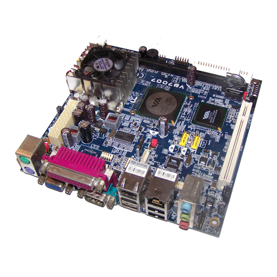
Page 15: Mainboard Layout
VB7007 User Manual Mainboard Layout ATX Power VIA C7 processor KB/MS CPU_Fan SYS_Fan DDR2 Memory slot CN700 North Bridge Buzzer COM3 SMBus COM4 COM2 Inverter PVDD IVDD_SEL VT8237S South Bridge Battery Front Panel Clear CMOS Front Audio USB_0/1 SATA SPDIF USB_2/3 LVDS Panel... -
Page 16: Back Panel Layout
VB7007 User Manual Back Panel Layout... -
Page 17: 2: Installation
VB7007 User Manual Installation This chapter provides you with information about hardware installation procedures. It is recommended to use a grounded wrist strap before handling computer components. Electrostatic discharge (ESD) can damage some components. -
Page 18: Cpu
VB7007 User Manual ® The VIA VB7007 mainboard is packaged with either the VIA C7 -D 1.6 GHz or VIA ® ® 1.0 GHz NanoBGA2 processor. The VIA C7 -D 1.6 GHz processor requires a ® heatsink with fan to provide sufficient cooling. The VIA C7 1.0 GHz processor is for fanless solutions. -
Page 19: Memory Module Installation
VB7007 User Manual Memory Module Installation Memory Slot: DDR2 DIMM The VIA VB7007 mainboard has one 240-DIMM slot for DDR2 667/533 SDRAM memory modules and supports memory sizes up to 1 GB. 1 GB SDRAM only supported with 64 MB x 8-bit x 16 configuration. -
Page 20: Ddr2 Sdram Module Installation Procedures
VB7007 User Manual DDR2 SDRAM Module Installation Procedures • Locate the DIMM slot in the motherboard. • Unlock a DIMM slot by pressing the retaining clips outward. • Align a DIMM on the socket such that the notch on the DIMM matches the break on the slot. -
Page 21: Connecting The Power Supply
VB7007 User Manual Connecting the Power Supply The VIA VB7007 mainboard supports a conventional ATX power supply for the power system. Before inserting the power supply connector, always make sure that all components are installed correctly to ensure that no damage will be caused. -
Page 22: Atx 20-Pin Power Connector
VB7007 User Manual ATX 20-Pin Power Connector To connect the power supply, make sure the power plug is inserted in the proper orientation and the pins are aligned. Then push down the plug firmly into the connector. Signal Signal +3.3V +3.3V +3.3V -12V... -
Page 23: Back Panel Ports
VB7007 User Manual Back Panel Ports The back panel has the following ports: PS/2 ports: mouse and keyboard The green PS/2 port is used to connect a mouse. The purple PS/2 port is used to connect a keyboard. VGA port The 15-pin VGA port is for connecting to analog displays. -
Page 24: Connectors
VB7007 User Manual Connectors Serial ATA Connectors: SATA1 and SATA2 The current SATA interface allows up to 300 MB/s data transfer rate, faster than the standard parallel ATA with 133 MB/s (Ultra DMA). -
Page 25: Ide Connector: Ide1
VB7007 User Manual IDE Connector: IDE1 The mainboard has an Ultra DMA 133/100/66/33 controller. You can connect up to two IDE devices in any combination. Signal Signal -IDERST1 PD_7 PD_8 PD_6 PD_9 PD_5 PD_10 PD_4 PD_11 PD_3 PD_12 PD_2 PD_13 PD_1 PD_14 PD_0... - Page 26 VB7007 User Manual USB Pin Connector: USB_0/1 and USB_2/3 The mainboard provides two 10-pin USB pin connectors (allowing up to four additional USB 2.0 ports). USB_0/1 Signal Signal VUSB0 VUSB0 USBD_T0- USBD_T1- USBD_T0+ USBD_T1+ USB_2/3 Signal Signal VUSB0 VUSB0 USBD_T2- USBD_T3- USBD_T2+ USBD_T3+...
-
Page 27: Digital I/O Connector: Dio
VB7007 User Manual Digital I/O Connector: DIO General purpose digital input and output. Signal Signal +12V GPO1 GPI4 GPO7 GPI13 GPO26 GPI14 GPO27 GPI15... -
Page 28: System Management Bus Connector: Smbus
VB7007 User Manual System Management Bus Connector: SMBUS This pin header allows you to connect SMBus (System Management Bus) devices. Devices communicate with a SMBus host and/or other SMBus devices using the SMBus interface. Signal SMBCK SMBDT Serial Port Connector: COM2/3/4 COM pin headers can be used to attach an additional port for serial devices. -
Page 29: Case Connector: F_Panel
VB7007 User Manual Case Connector: F_PANEL The F_PANEL pin header allows you to connect the power switch, reset switch, power LED, sleep LED, HDD LED and the case speaker. Signal Signal +5VDUAL +5VDUAL HD_LED -PLED_2 PW_BN RST_SW SPEAK -SLEEP_LED Power LED (PLED) The LED will light when the system is on. -
Page 30: Kbms Connector: Kb/Ms
VB7007 User Manual KBMS Connector: KB/MS The mainboard provides a PS2 pin header to attach a PS2 keyboard and mouse. Signal Signal +5VDUAL KB_CLK KB_DATA EKBCLK EKBDATA MS_CLK MS_DATA EMSCLK EMSDATA... -
Page 31: Fast Infrared Connector: Fir
VB7007 User Manual Fast Infrared Connector: FIR Signal IRRX1 IRRX IRTX S/PDIF Connector: SPDIF Signal SPDIF_OUT... -
Page 32: Front Audio: F_Audio
VB7007 User Manual Front Audio: F_AUDIO This connector allows you to connect a front audio panel to the mainboard. Signal Signal MIC2_IN_L AGND MIC2_IN_R +3.3V HP_OUT_R HP_OUT_L... -
Page 33: Lvds Connector: Panel_Conn
VB7007 User Manual LVDS Connector: PANEL_CONN Signal Signal -A4_L PVDD A4_L PVDD -A5_L A5_L -A0_L A0_L -A6_L A6_L -A1_L A1_L -CLK2_L CLK2_L -A2_L A2_L -A7_L A7_L -CLK1_L CLK1_L -A3_L A3_L SPCLK1 SPD1 LVDS Inverter: INVERTER Signal BAKLITE BAKLITE SMBUS OUT... -
Page 34: Jumpers
VB7007 User Manual Jumpers The mainboard provides jumpers for setting some mainboard functions. This section will explain how to change the settings of the mainboard functions using the jumpers. Clear CMOS Connector: CLEAR_CMOS The onboard CMOS RAM stores system configuration data and has an onboard battery power supply. -
Page 35: Panel Power Selector: Pvdd
VB7007 User Manual Panel Power Selector: PVDD Setting 3.3V Inverter Power Selector: IVDD_SEL Setting... -
Page 36: Slots
VB7007 User Manual Slots Peripheral Component Interconnect: PCI_SLOT The PCI slot allows you to insert a PCI expansion card. First unplug the power supply before adding or removing expansion cards. Read the documentation for the expansion card to see if any changes to the system are necessary. PCI Interrupt Request Routing The IRQ (interrupt request line) are hardware lines over which devices can send interrupt signals to the microprocessor. -
Page 37: 3: Bios Setup
VB7007 User Manual BIOS Setup This chapter gives a detailed explanation of the BIOS setup functions. -
Page 38: Entering The Bios Setup Menu
VB7007 User Manual Entering the BIOS Setup Menu Power on the computer and press <Delete> during the beginning of the boot sequence to enter the BIOS setup menu. If you missed the BIOS setup entry point, restart the system and try again. -
Page 39: Control Keys
VB7007 User Manual Control Keys Keys Description Move to the previous item Move to the next item Move to the item in the left side Move to the item in the right side Select the item Enter Jumps to the Exit menu or returns to the main menu from a submenu Increase the numeric value or make changes Page... - Page 40 VB7007 User Manual Keys Description General help, only for Status Page Setup Menu and Option Page Setup Menu Restore the previous CMOS value from CMOS, only for Option Page Setup Menu Load the default CMOS value from Fail-Safe default table, only for Option Page Setup Menu Load Optimized defaults Save all the CMOS changes and exit...
-
Page 41: Navigating The Bios Menus
VB7007 User Manual Navigating the BIOS Menus The main menu displays all the BIOS setup categories. Use the <Left>/<Right> and <Up>/<Down> arrow keys to select any item or sub-menu. Descriptions of the selected/highlighted category are displayed at the bottom of the screen. The small triangular arrowhead symbol next to a field indicates that a sub-menu is available (see figure below). -
Page 42: Getting Help
VB7007 User Manual Getting Help The BIOS setup program provides a “General Help” screen. You can display this screen from any menu/sub-menu by pressing <F1>. The help screen displays the keys for using and navigating the BIOS setup. Press <Esc> to exit the help screen. -
Page 43: Main Menu
VB7007 User Manual Main Menu The Main Menu contains thirteen setup functions and two exit choices. Use arrow keys to select the items and press <Enter> to accept or enter Sub-menu. Standard CMOS Features Use this menu to set basic system configurations. Advanced BIOS Features Use this menu to set the advanced features available on your system. -
Page 44: Pc Health Status
VB7007 User Manual PnP/PCI Configurations Use this menu to set the PnP and PCI configurations. PC Health Status This menu shows the PC health status. Frequency/Voltage Control Use this menu to set the system frequency and voltage control. Load Optimized Defaults Use this menu option to load BIOS default settings for optimal and high performance system operations. -
Page 45: Standard Cmos Features
VB7007 User Manual Standard CMOS Features Date The date format is [Day, Month Date, Year] Time The time format is [Hour : Minute : Second] Halt On Set the system’s response to specific boot errors. Below is a table that details the possible settings. -
Page 46: Ide Channels
VB7007 User Manual IDE Channels The specifications of your drive must match with the drive table. The hard disk will not work properly if you enter incorrect information in this category. Select “Auto” whenever possible. If you select “Manual”, make sure the information is from your hard disk vendor or system manufacturer. -
Page 47: Advanced Bios Features
VB7007 User Manual Advanced BIOS Features Virus Warning Allows you to choose the VIRUS warning feature for IDE Hard Disk boot sector protection. Settings Description Enabled Turns on hard disk boot sector virus protection Disabled Turns off hard disk boot sector virus protection Note: If this function is enabled and someone attempt to write data into this area, BIOS will show a warning message on the screen and alarm beep. -
Page 48: Cpu L2 Cache Ecc Checking
VB7007 User Manual CPU L2 Cache ECC Checking This feature facilitates error detection/correction when data passes through Level 2 cache. Settings: [Disabled, Enabled] Quick Power On Self-Test Shortens Power On Self-Test (POST) cycle to enable shorter boot up time. Settings Description Disabled Standard Power On Self Test (POST) -
Page 49: Security Option
VB7007 User Manual Typematic Rate (Chars/Sec) This item sets the rate (characters/second) at which the system retrieves a signal from a depressed key. Settings: [6, 8, 10, 12, 15, 20, 24, 30] Typematic Delay (Msec) This item sets the delay between, when the key was first pressed and when the system begins to repeat the signal from the depressed key. -
Page 50: Cpu Feature
VB7007 User Manual CPU Feature Thermal Management This item sets CPU’s thermal control rule to protect CPU from overheat. Settings Description Thermal Monitor 1 On-die throttling... -
Page 51: Hard Disk Boot Priority
VB7007 User Manual Hard Disk Boot Priority This is for setting the priority of the hard disk boot order when the “Hard Disk” option is selected in the “[First/Second/Third] Boot Device” menu item. -
Page 52: Advanced Chipset Features
VB7007 User Manual Advanced Chipset Features Caution: The Advanced Chipset Features menu is used for optimizing the chipset functions. Do not change these settings unless you are familiar with the chipset. Display Card Priority Settings: [PCI Slot, AGP] Video RAM Cacheable Settings: [Disabled, Enabled] AGP Driving Control Settings: [Auto, Manual]... -
Page 53: Agp Driving Value
VB7007 User Manual AGP Driving Value This option can only be altered if “AGP Driving Control” is set to “Manual”. Input is expected as hexidecimal Select Display Device Settings: [CRT, LCD, CRT&LCD] Panel Type Settings Description 640 x 480 800 x 600 1024 x 768 1280 x 768 1280 x 1024... -
Page 54: Agp Aperture Size
VB7007 User Manual AGP & P2P Bridge Control AGP Aperture Size This setting controls how much memory space can be allocated to AGP for video purposes. The aperture is a portion of the PCI memory address range dedicated to graphics memory address space. Host cycles that hit the aperture range are forwarded to the AGP without any translation. -
Page 55: Vga Share Memory Size
VB7007 User Manual AGP 3.0 Calibration Cycle Settings: [Disabled, Enabled] VGA Share Memory Size This setting allows you to select the amount of system memory that is allocated to the integrated graphics processor. Settings: [Disabled, 16M, 32M, 64M] Direct Frame Buffer Settings: [Disabled, Enabled] Outport Port Settings: [DI0, DI1]... -
Page 56: Cpu & Pci Bus Control
VB7007 User Manual CPU & PCI Bus Control VLink Mode Selection Settings: [By Auto, Mode 0, Mode 1] VLink 8X Support Settings: [Disabled, Enabled] DRDY_Timing Settings: [Slowest, Default, Optimize]... -
Page 57: Integrated Peripherals
VB7007 User Manual Integrated Peripherals Onboard IDE Channel 1 and 2 The integrated peripheral controller contains an IDE interface with support for two IDE channels. Settings: [Disabled, Enabled] IDE Prefetch Mode This allows your hard disk controller to use the fast block mode to transfer data to and from the hard disk drive. -
Page 58: Sata Controller
VB7007 User Manual SATA Controller Settings: [Disabled, Enabled] SATA Controller Mode Controls the features of the Serial ATA controller within the South Bridge. Serial ATA is the latest generation of the ATA interface. Serial ATA hard drives deliver transfer speeds of up to 300MB/sec. Settings Description Supports two PATA hard disk drives. -
Page 59: Watchdog Support
VB7007 User Manual WatchDog Support Settings: [Enabled, Disabled] Watch Dog Timer Select This option can only be altered if “WatchDog Support” is enabled. Settings: [Minute, Second] Watch Dog Count Value This option can only be altered if “WatchDog Support” is enabled. Settings: [any integer from 0 to 255]... -
Page 60: Superio Device
VB7007 User Manual SuperIO Device Onboard Serial Port 1/2/3/4 Set the base I/O port address and IRQ for the onboard serial port A / serial port B. Selecting Auto allows BIOS to automatically determine the correct base I/O port address. Settings: Port Settings Disabled... -
Page 61: Parallel Port Mode
VB7007 User Manual Parallel Port Mode Set the parallel port mode. To operate the onboard parallel port as Standard Parallel Port, choose SPP. To operate the onboard parallel port in the EPP mode, choose EPP. By choosing ECP, the onboard parallel port will operate in ECP mode. Choosing ECP + EPP will allow the onboard parallel port to support both the ECP and EPP modes simultaneously. -
Page 62: Via Onchip Ide Device
VB7007 User Manual VIA OnChip IDE Device DOM support UDMA66 Settings: [Disabled, Enabled] IDE DMA Transfer Access Settings: [Disabled, Enabled]... -
Page 63: Usb Device Setting
VB7007 User Manual USB Device Setting USB 1.0 Controller Enable or disable Universal Host Controller Interface for Universal Serial Bus. Settings: [Disabled, Enabled] USB 2.0 Controller Enable or disable Enhanced Host Controller Interface for Universal Serial Bus. Settings: [Disabled, Enabled] USB Operation Mode Auto decide USB device operation mode. -
Page 64: Usb Keyboard Function
VB7007 User Manual USB Keyboard Function Enable or disable Legacy support of USB Keyboard. Settings: [Disabled, Enabled] USB Mouse Function Enable or disable Legacy support of USB Mouse. Settings: [Disabled, Enabled] USB Storage Function Enable or disable Legacy support of USB Mass Storage. Settings: [Disabled, Enabled]... -
Page 65: Power Management Setup
VB7007 User Manual Power Management Setup ACPI Suspend Type Settings Description S1(POS) S1/Power On Suspend (POS) is a low power state. In this state, no system context (CPU or chipset) is lost and hardware maintains all system contexts. S3(STR) S3/Suspend To RAM (STR) is a power-down state. In this state, power is supplied only to essential components such as main memory and wakeup-capable devices. -
Page 66: Power Management Timer
VB7007 User Manual Power Management Timer Settings: [Disable, 1 Min, 2 Min, 4 Min, 6 Min, 8 Min, 10 Min, 20 Min, 30 Min, 40 Min, 1 Hour] Video Off Option Select whether or not to turn off the screen when system enters power saving mode, ACPI OS such as Windows XP will override this option. -
Page 67: Peripherals Activities
VB7007 User Manual Peripherals Activities PS2KB Wakeup Select This feature has two settings: Hot Key and Password. To select the Password option, press <Page Up> or <Page Down>. To set the password, enter up to eight digits and press <Enter>. Settings: [Hot Key, Password] PS2KB Wakeup Key Select This feature is only available when “Hot Key”... -
Page 68: Ps2 Mouse Power On
VB7007 User Manual PS2 Mouse Power ON Settings: [Disabled, Enabled] USB Resume Settings: [Disabled, Enabled] PowerOn by PCI Card Enables activity detected from any PCI card to power up the system or resume from a suspended state. Such PCI cards include LAN, onboard USB ports, etc. Settings: [By OS, Enabled] RTC Alarm Resume Set a scheduled time and/or date to automatically power on the system. -
Page 69: Pnp/Pci Configurations
VB7007 User Manual PnP/PCI Configurations Note: This section covers some very technical items and it is strongly recommended to leave the default settings as is unless you are an experienced user. PNP OS Installed Settings Description BIOS will initialize all the PnP cards BIOS will only initialize the PnP cards used for booting (VGA, IDE, SCSI). -
Page 70: Reset Configuration Data
VB7007 User Manual Reset Configuration Data Settings Description Disabled Default setting Enabled Resets the ESCD (Extended System Configuration Data) after exiting BIOS Setup if a newly installed PCI card or the system configuration prevents the operating system from loading Resources Controlled By Enables the BIOS to automatically configure all the Plug-and-Play compatible devices. -
Page 71: Irq Resources
VB7007 User Manual IRQ Resources IRQ Resources list IRQ 7/9/10/11/12/14/15 for users to set each IRQ a type depending on the type of device using the IRQ. Settings: For Plug-and-Play compatible devices designed for PCI bus PCI Device architecture Reserved The IRQ will be reserved for further requests... -
Page 72: Pc Health Status
VB7007 User Manual PC Health Status The PC Health Status displays the current status of all of the monitored hardware devices/components such as CPU voltages, temperatures and fan speeds. -
Page 73: Frequency/Voltage Control
VB7007 User Manual Frequency/Voltage Control DRAM Clock The chipset supports synchronous and asynchronous mode between host clock and DRAM clock frequency. Settings: [By SPD, 200 MHz, 266 MHz] DRAM Timing The value in this field depends on the memory modules installed in your system. Changing the value from the factory setting is not recommended unless you install new memory that has a different performance rating than the original modules. -
Page 74: Sdram Cas Latency
VB7007 User Manual SDRAM CAS Latency This item adjusts the speed it takes for the memory module to complete a command. Generally, a lower setting will improve the performance of your system. However, if your system becomes less stable, you should change it to a higher setting. -
Page 75: Auto Detect Pci Clk
VB7007 User Manual REF to ACT/REF (Trfc) This field is only available when “DRAM Timing” is set to “Manual”. Settings: [08T - 71T] ACT(0) to ACT(1) (TRRD) This field is only available when “DRAM Timing” is set to “Manual”. Settings: [2T - 5T] Read to Precharge (Trtp) Settings: [2T, 3T] Write to Read CMD (Twtr) - Page 76 VB7007 User Manual Load Optimized Defaults This option is for restoring all the default optimized BIOS settings. The default optimized values are set by the mainboard manufacturer to provide a stable system with optimized performance. Entering “Y” and press <Enter> to load the default optimized BIOS values.
-
Page 77: Set Supervisor/User Password
VB7007 User Manual Set Supervisor/User Password This option is for setting a password for entering BIOS Setup. When a password has been set, a password prompt will be displayed whenever BIOS Setup is run. This prevents an unauthorized person from changing any part of your system configuration. - Page 78 VB7007 User Manual Additionally, when a password is enabled, the BIOS can be set to request the password each time the system is booted. This would prevent unauthorized use of the system. See “Security Option” in the “Advanced BIOS Features” section for more details.
-
Page 79: Save & Exit Setup
VB7007 User Manual Save & Exit Setup Entering “Y” saves any changes made, and exits the program. Entering “N” will cancel the exit request. -
Page 80: Exit Without Saving
VB7007 User Manual Exit Without Saving Entering “Y’ discards any changes made, and exits the program. Entering “N” will cancel the exit request. -
Page 81: Driver Installation
VB7007 User Manual Driver Installation This chapter gives you brief descriptions of each mainboard driver and application. You must install the VIA chipset drivers first before installing other drivers such as VGA drivers. The applications will only function correctly if the necessary drivers are already installed. -
Page 82: Driver Utilities
VB7007 User Manual Driver Utilities Getting Started VIA VB7007 Developer kits include a driver CD that contains the drivers and software for enhancing the performance of the mainboard. Regular kits do not include a driver CD. However, the latest drivers can be downloaded from http://www.via.com.tw. -
Page 83: Cd Content
VB7007 User Manual CD Content VIA 4in1 Drivers: Contains VIA ATAPI Vendor Support Driver (enables the performance enhancing bus mastering functions on ATA-capable Hard Disk Drives and ensures IDE device compatibility), AGP VxD Driver (provides service routines to your VGA driver and interface directly to hardware, providing fast graphical access), IRQ Routing Miniport Driver (sets the system's PCI IRQ routing sequence) and VIA INF Driver (enables the VIA Power Management function). - Page 84 53117 Bonn Taiwan Germany TEL: 886.2.2218.5452 TEL: 1.510.683.3300 TEL: 49.228.688565.0 FAX: 886.2.2218.5453 FAX: 49.228.688565.19 FAX: 1.510.687.4654 Email: embedded@via.com.tw Email: embedded@viatech.com Email: embedded@via-tech.de China Japan Korea Tsinghua Science Park Bldg. 7 3-15-7 Ebisu MT Bldg. 6F 2F, Sangjin Bldg., 417 Higashi, Shibuya-ku No.
Need help?
Do you have a question about the Board and is the answer not in the manual?
Questions and answers