VIA Technologies VAB-630 User Manual
Cost effective single board computer with flexible i/o and rich connectivity
Hide thumbs
Also See for VAB-630:
- Quick start manual (26 pages) ,
- Installation manual (8 pages) ,
- Quick start manual (23 pages)

Related Manuals for VIA Technologies VAB-630


Summary of Contents for VIA Technologies VAB-630
- Page 1 USER MANUAL VAB-630 Cost effective single board computer with flexible I\O and rich connectivity 1.03-12312017-162000...
- Page 2 VIA Technologies, Inc. reserves the right the make changes to the products described in this manual at any time without prior notice. Regulatory Compliance FCC-A Radio Frequency Interference Statement This equipment has been tested and found to comply with the limits for a class A digital device, pursuant to part 15 of the FCC rules.
-
Page 3: Safety Precautions
Battery Recycling and Disposal Only use the appropriate battery specified for this product. Do not re-use, recharge, or reheat an old battery. Do not attempt to force open the battery. Do not discard used batteries with regular trash. Discard used batteries according to local regulations. Safety Precautions Always read the safety instructions carefully. -
Page 4: Box Contents
VAB-630 User Manual Box Contents VAB-630 1 x VAB-630 mainboard (with 1.0GHz VIA Cortex-A9 dual-core SoC) 1 x RTC battery Ordering Information Part Number Description SBC with 1.0GHz VIA Cortex-A9 SoC, 4GB eMMC, 1GB DDR3 SDRAM 10GHL126000A0 2 x USB 2.0, Micro USB 2.0 OTG, HDMI, COM, DIO, 10/100Mbps Ethernet, Micro SD card slot, and 12V DC-in. -
Page 5: Table Of Contents
A.1. Installing the EMIO-2550 miniPCIe mobile broadband module ............24 A.2. Installing the EMIO-2531 miniPCIe Wi-Fi & Bluetooth module .............. 27 A.3. Installing EMIO-5531 USB Wi-Fi module ..................... 29 Appendix B. Installing LVDS Panel Display .................. 31 B.1. Connecting the LVDS Panel Display to the VAB-630 board ..............31... - Page 6 VAB-630 User Manual Appendix C. Connector Vendor Lists .................... 33 C.1. VAB-630 Mainboard ............................33...
- Page 7 Figure 1: Layout diagram of the VAB-630 (top view) ....................4 Figure 2: Layout diagram of the VAB-630 (bottom view) ...................4 Figure 3: Mounting holes and dimensions of the VAB-630 (top view) ..............5 Figure 4: External I/O port dimensions of the VAB-630 (front panel) ..............5 Figure 5: External I/O port dimensions of the VAB-630 (back panel) ..............5...
- Page 8 VAB-630 User Manual Figure 47: Connecting the antenna cable to the micro-RF connector ..............30 Figure 48: Connecting the touch screen cable to the touch controller module ..........31 Figure 49: Connecting the USB touch cable ....................... 31 Figure 50: Connecting the flex flat cable ........................32...
- Page 9 Table 17: Battery connector pinouts ..........................18 Table 18: Reset connector pinouts ..........................18 Table 19: RTC battery connector pinouts ........................19 Table 20: UART connector pinouts ..........................19 Table 21: USB 2.0 connector pinouts ..........................20 Table 22: VAB-630 connector vendor lists ........................33...
-
Page 10: Product Overview
VAB-630 User Manual 1. Product Overview Based with a compacted 3.5 inch SBC and measuring at 14.6cm x 10.2cm, the VIA VAB-630 is a highly integrated based ARM board. It’s powered by 1.0GHz VIA Cortex-A9 dual-core processor. The VIA VAB- 630 combines two independent, integrated GPUs for 3D/2D graphics acceleration, in addition it offers support for MPEG-2 and H.264 video decoding up to 1080p. -
Page 11: Product Specifications
VAB-630 User Manual 1.2. Product Specifications Processor o 1.0GHz VIA Cortex-A9 dual-core SoC System Memory o 1GB DDR3 SDRAM onboard Storage o 4GB eMMC Flash memory Boot Loader o 512KB SPI Flash ROM Graphics o Mali-400 SP GPU • 2-integrated, independent 3D/2D graphics processing units •... - Page 12 VAB-630 User Manual Back Panel I/O o 1 x HDMI port o 2 x USB 2.0 ports o 1 x COM port for RS-232 (TX/RX) o 1 x 10/100Mbps Ethernet port o 1 x DC in-jack Power Supply o 12V DC-in (5V DC-in optional) Operating Temperature o 0°C ~ 60°C...
-
Page 13: Layout Diagram
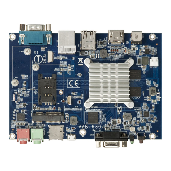
USB 2.0 1.0GHz VIA Cortex-A9 dual-core SoC SIM Card slot DDR3 SDRAM Battery connector UART External I/O Figure 1: Layout diagram of the VAB-630 (top view) I C touch LVDS Figure 2: Layout diagram of the VAB-630 (bottom view) -
Page 14: Product Dimensions
VAB-630 User Manual 1.4. Product Dimensions O 3.5mm (hole) 70.5mm 102mm 146mm Figure 3: Mounting holes and dimensions of the VAB-630 (top view) 132.5mm 119.5mm 101mm 86mm 45.5mm 28mm 19.5mm 1.4mm Figure 4: External I/O port dimensions of the VAB-630 (front panel) -
Page 15: Height Distribution
VAB-630 User Manual 1.5. Height Distribution Figure 6: Height distribution of the VAB-630 (top view) Figure 7: Height distribution of the VAB-630 (bottom view) -
Page 16: I/O Interface
VAB-630 User Manual 2. I/O Interface The VAB-630 has a selection of interfaces integrated into the board. It includes a selection of frequently used ports as part of the external I/O coastline. 2.1. External I/O Ports Figure 8: Front panel I/O... -
Page 17: Micro Sd Card Slot
VAB-630 User Manual 2.1.1. Micro SD Card Slot The main board comes with a Micro SD card slot located on the front panel with support for a maximum storage capacity of 32GB. The pinouts of the Micro SD card slot are shown below. -
Page 18: Usb 2.0 Port
VAB-630 User Manual The 10/100Mbps Ethernet port (RJ-45) is equipped with two LED indicators on the front side to show its Active/ Link status and Speed status. Link LED Active LED (Left LED on RJ-45 port) (Right LED on RJ-45 port) -
Page 19: Audio Jacks
VAB-630 User Manual 2.1.4. Audio Jacks The mainboard offers High Definition Audio through 3.5mm Tip Ring Sleeve (TRS) connector to enable connections to Line-out and Mic-in. The Line-out jack is for connecting to external speakers or headphones. The Mic-in is for connecting to a microphone. -
Page 20: Dio Port
VAB-630 User Manual 2.1.6. DIO Port The mainboard comes with a female DIO port for digital I/O communication interface port. The DIO port is using D-sub 15-pin connector. The pinouts of the DIO port are shown below. Figure 15: DIO port diagram... -
Page 21: Power Button
VAB-630 User Manual 2.1.8. Power Button The mainboard is equipped with a power button. The Power button can support four functions. The table below will explain how the functions work. Figure 17: Power button diagram Power Button Behavior Quickly press the power button once to suspend. While in suspending... -
Page 22: Com Port
VAB-630 User Manual 2.1.10. COM Port The mainboard is equipped 9-pin COM port uses a male DE-9 connector. The COM port supports the RS-232 standard. The pinouts of the COM port are shown below. Figure 20: COM port diagram Signal... -
Page 23: Onboard Connectors
The mainboard is equipped with SIM card slot that can support 3G SIM card. Using the SIM card slot on the VAB-630 mainboard requires a 3G module installed in the miniPCIe slot to enable the 3G function, otherwise the SIM card slot will be disabled. The SIM card slot is designed only for 3G module without built-in SIM card slot on it. -
Page 24: Minipcie Slot
VAB-630 User Manual 2.2.2. MiniPCIe Slot The mainboard is equipped with miniPCIe slot for wireless networking option such as WPAN/Wi-Fi/ WWAN. The miniPCIe slot is compatible with all PCIe 2.0 miniPCIe modules full-length. The pinouts of the miniPCIe slot are shown below. -
Page 25: C Touch Connector
VAB-630 User Manual 2.2.3. I C Touch Connector The mainboard is equipped with an I²C touch connector for connecting resistive touch panel. The I²C touch connector is labeled as "JTOUCH1". The pinouts of the I C touch connector are shown below. -
Page 26: Lvds Panel Connector
VAB-630 User Manual 2.2.4. LVDS Panel Connector The mainboard has a LVDS panel connector on the bottom side which is used to connect the panel’s LVDS cable to support the single-channel 18/24-bit display. Backlight controls are integrated into the LVDS panel connector pinouts. The LVDS panel connector is labeled as “LVDS1”. The pinouts of the LVDS panel connector are shown below. -
Page 27: Battery Connector
A well packed 4.2V battery with overcharge prevention and over discharge prevention/protection function embedded in battery pack is required to be used with VAB-630.The battery connector is labeled as “J3”. The connector pinouts are shown below. -
Page 28: Rtc Battery Connector
VAB-630 User Manual 2.2.7. RTC Battery Connector The mainboard is equipped with is equipped with an onboard RTC battery connector which is used for connecting the external cable battery that provides power to the 32.768KHz crystal oscillator for Real Time Clock (RTC). The RTC battery connector is labeled as “J53”. The pinouts of the RTC battery connector are shown below. -
Page 29: Usb 2.0 Connector
VAB-630 User Manual 2.2.9. USB 2.0 Connector The mainboard includes one USB 2.0 connector designed for connecting the USB Wi-Fi module (EMIO- 5531). The pinouts of the pin header are shown below. Figure 30: USB 2.0 connector diagram Signal USBT1+... -
Page 30: Hardware Installation
3. Hardware Installation 3.1. Installing into a Chassis The VAB-630 can be fitted into any chassis that has the mounting holes compatible with the standard SBC mounting holes locations. Additionally, the chassis must meet the minimum height requirements for specified areas of the mainboard. -
Page 31: Suggested Keepout Areas
VAB-630 User Manual 3.1.3. Suggested keepout areas The figure below shows the areas of the mainboard that is highly suggested to leave unobstructed. The figures below are the top view and the bottom view. Figure 33: Suggested keepout top areas... -
Page 32: Software And Technical Supports
VAB-630 User Manual 4. Software and Technical Supports 4.1. Android Support The VAB-630 features a complete software evaluation image featuring Android 5.0 operating system. 4.2. Technical Supports and Assistance • For utilities downloads, latest documentation and new information about VAB-630, please visit our website https://www.viatech.com/en/boards/3-5-inch-sbc/vab-630/... -
Page 33: Appendix A. Installing Wireless Accessories
This chapter provides you with information on how to install the EMIO modules and connect LVDS panel display into the VAB-630 board. It is recommended to use a grounded wrist strap before handling computer components. Electrostatic discharge (ESD) can damage some components. -
Page 34: Figure 36: Inserting The Emio-2550 Module
VAB-630 User Manual Step 2 Align the notch on the EMIO-2550 module with the counterpart on the miniPCIe slot then insert the module at 30° angle. Figure 36: Inserting the EMIO-2550 module Step 3 Once the module has been fully inserted, push down the module until the screw holes align with the mounting hole on the standoff. -
Page 35: Figure 38: Connecting The Antenna Cable And Antenna
VAB-630 User Manual Step 4 Insert the 3G antenna cable into the antenna hole from the inside of the back panel plate. Insert the washer, fasten it with the nut and install the external antenna. Figure 38: Connecting the antenna cable and antenna Step 5 Gently connect the other end of the 3G antenna cable to the micro-RF connector labeled “MAN”... -
Page 36: Installing The Emio-2531 Minipcie Wi-Fi & Bluetooth Module
VAB-630 User Manual A.2. Installing the EMIO-2531 miniPCIe Wi-Fi & Bluetooth module Step 1 Align the notch on the EMIO-2531 module with the counterpart on the miniPCIe slot then insert the module at 30° angle. Figure 40: Inserting the EMIO-2531 module... -
Page 37: Figure 42: Connecting The Wi-Fi Antenna Cable And Antenna
VAB-630 User Manual Step 3 Insert the Wi-Fi antenna cable into the antenna hole from the inside of the back panel plate. Insert the washer, fasten it with the nut and install the external antenna. Figure 42: Connecting the Wi-Fi antenna cable and antenna Step 4 Gently connect the other end of the Wi-Fi antenna cable to the micro-RF connector labeled “MH2”... -
Page 38: Installing Emio-5531 Usb Wi-Fi Module
Step 2 Attach the USB Wi-Fi cable (P/N 99G33-193126) to the connector on EMIO-5531 module, and then attach the other end of the cable to the onboard USB Wi-Fi connector (JUSB1) on the VAB-630 mainboard. Figure 45: Connecting USB Wi-Fi cable... -
Page 39: Figure 46: Connecting The Antenna Cable And Antenna
VAB-630 User Manual Step 3 Insert the Wi-Fi antenna cable into the antenna hole from the inside of the back panel plate. Insert the washer, fasten it with the nut and install the external antenna. Figure 46: Connecting the antenna cable and antenna Step 4 Gently connect the other end of the Wi-Fi antenna cable to the micro-RF connector labeled “MH2”... -
Page 40: Appendix B. Installing Lvds Panel Display
VAB-630 User Manual Appendix B. Installing LVDS Panel Display B.1. Connecting the LVDS Panel Display to the VAB-630 board Step 1 Attach the touch screen flat flex cable into the touch controller module. i s p i s p l a y... -
Page 41: Figure 50: Connecting The Flex Flat Cable
VAB-630 User Manual Step 3 Connect the flex flat cable connector to the LVDS panel display backside and then into the VAB-630 backside of the mainboard. The blue color side of the LVDS cable must face up when connecting to the LVDS panel (both panel and board). -
Page 42: Table 22: Vab-630 Connector Vendor Lists
VAB-630 User Manual Appendix C. Connector Vendor Lists The following tables listed the connector vendors of VAB-630 mainboard. C.1. VAB-630 Mainboard Connectors VIA P/N Vendor ACES 99G30-170252 87213-0800G ACES JTOUCH1 99H30-171352 50271-0060N-001 ACES LVDS1 99H30-03255C 50501-04041-001 MOST WELL 99H30-02091G W3962-S1021221...
Need help?
Do you have a question about the VAB-630 and is the answer not in the manual?
Questions and answers