Table of Contents
Advertisement
Advertisement
Table of Contents

Subscribe to Our Youtube Channel
Related Manuals for VIA Technologies 7001G - VIA Mini ITX Motherboard


Summary of Contents for VIA Technologies 7001G - VIA Mini ITX Motherboard
- Page 1 User’s Manual VB7001 Version 1.13 January 18, 2012...
- Page 2 Copyright Copyright © 2010-2012 VIA Technologies Incorporated. All rights reserved. No part of this document may be reproduced, transmitted, transcribed, stored in a retrieval system, or translated into any language, in any form or by any means, electronic, mechanical, magnetic, optical, chemical, manual or otherwise without the prior written permission of VIA Technologies, Incorporated.
-
Page 3: Safety Instructions
Safety Instructions Always read the safety instructions carefully. Keep this User's Manual for future reference. Keep this equipment away from humidity. Lay this equipment on a reliable flat surface before setting it up. The openings on the enclosure are for air convection hence protects the equipment from overheating. - Page 5 ONTENTS One VIA Mini-ITX mainboard One Quick Installation Guide One ATA-133/100 IDE ribbon cable One driver and utilities CD One IO bracket...
-
Page 6: Table Of Contents
ABLE OF ONTENTS Box Contents................i Table of Contents ..............ii Chapter 1 ................1 Specifications ............... 1 Mainboard Specifications ............2 Mainboard Layout ..............4 Back Panel Layout ..............5 Chapter 2 ................7 Installation................7 CPU ..................8 Memory Module Installation .......... - Page 7 Power Management Setup ............ 45 Peripheral Activities ............47 IRQs Activities ..............50 PNP/PCI Configurations ............51 IRQ Resources ..............53 Frequency / Voltage Control ..........54 Load Fail-Safe Defaults ............58 Load Optimized Defaults ............59 Set Supervisor / User Password ..........60 Save &...
- Page 8 This page is left intentionally blank.
-
Page 9: Chapter 1
HAPTER Specifications The ultra-compact and highly integrated VIA VB7001 uses the Mini-ITX mainboard form-factor developed by VIA Technologies, Inc. part company’s open industry-wide total connectivity initiative. The mainboard enables the creation of an exciting new generation of small, ergonomic, innovative and... -
Page 10: Mainboard Specifications
Chapter 1 AINBOARD PECIFICATIONS ® VIA C7 -D 1.5GHz NanoBGA2 Processor Chipset VIA CN700 North Bridge VIA VT8237R Plus South Bridge Graphics Integrated UniChrome™ Pro AGP with MPEG-2 Acceleration Audio VIA VT1618 AC'97 Codec Memory 1 x DDR2 533 DIMM slot (up to 1 GB) Expansion Slot 1 x PCI slot 2 x UltraDMA 133/100/66 connectors... - Page 11 Specifications 1 x Buzzer 1 x ATX Power connector Back Panel I/O Ports 1 x PS/2 mouse port and 1 x PS/2 keyboard port 1 x RJ-45 LAN port 1 x Serial port 1 x VGA port 2 x USB 2.0 ports 3 x Audio Jacks: Line-out, Line-in and Mic-in 1 x RCA port for Composite TV output (optional) or Coaxial S/PDIF...
-
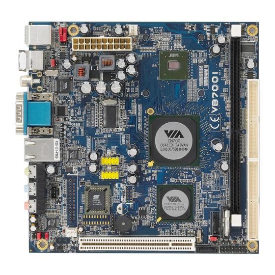
Page 12: Mainboard Layout
Chapter 1 AINBOARD AYOUT... -
Page 13: Back Panel Layout
Specifications ANEL AYOUT... - Page 14 This page is left intentionally blank.
-
Page 15: Chapter 2
HAPTER Installation This chapter provides with information about hardware installation procedures. It is recommended to use a grounded wrist strap before handling computer components. Electrostatic discharge (ESD) can damage some components. -
Page 16: Cpu
Chapter 3 The VIA VB7001 Mini-ITX mainboard includes an embedded VIA C7-D V4 Bus Processor. The VIA C7-D V4 Bus Processor requires a heatsink with a fan to provide sufficient cooling. - Page 17 BIOS Setup CPU Fan and System Fan: CPUFAN and SYSFAN The CPUFAN (CPU fan) and SYSFAN (system fan) run on +12V and maintain system cooling. When connecting the wire to the connectors, always be aware that the red wire is the Positive and should be connected to the +12V. The black wire is Ground and should always be connected to GND.
-
Page 18: Memory Module Installation
Chapter 3 EMORY ODULE NSTALLATION The VIA VB7001 Mini-ITX mainboard provides one 240-pin DIMM slot for DDR2 533 SDRAM memory modules and supports the memory size up to 1GB. DIMM DDR SDRAM Module Installation Procedures Locate the DIMM slot in the motherboard. Unlock a DIMM slot by pressing the retaining clips outward. -
Page 19: Connecting The Power Supply
BIOS Setup ONNECTING THE OWER UPPLY The VIA VB7001 Mini-ITX mainboard supports a conventional ATX power supply for the power system. Before inserting the power supply connector, always make sure that all components are installed correctly to ensure that no damage will be caused. ATX 20-Pin Power Connector To connect the ATX power supply, make sure the power plug is inserted in the proper orientation and the pins are aligned. -
Page 20: Back Panel Ports
Chapter 3 ANEL ORTS The back panel has the following ports: Mouse and Keyboard The connector above is for a PS/2 mouse, and the one below is for a PS/2 keyboard. RCA / SPDIF Jack The RCA jack connects to external composite video device or audio output device. - Page 21 BIOS Setup Serial port: COM The 9-pin COM port is for pointing devices or other serial devices. VGA Port The 15-pin female VGA connector can be used to connect to any analog VGA monitor. RJ45 10/100 LAN and USB Connector The mainboard provides a standard RJ-45 and USB 2.0 ports.
-
Page 22: Connectors
Chapter 3 ONNECTORS Hard Disk Connectors: IDE1 & IDE2 The mainboard has a 32-bit Enhanced IDE and Ultra DMA 133/100/66 controller that provides PIO mode 0~4, Bus Master, and Ultra DMA 133/100/66 functions. You can connect up to four hard disk drives, CD-ROM and other devices. - Page 23 BIOS Setup Case Connector: F_PANEL The F_PANEL pin header allows you to connect the power switch, reset switch, power LED, sleep LED, HDD LED and the case speaker. F_PANEL Signal Signal +5VDUAL +5VDUAL HD_LED -PLED_2 PW_BN RST_SW SPEAK -SLEEP_LED Power Switch (PW_BN) Connect to a 2-pin power button switch.
- Page 24 Chapter 3 Serial ATA Connectors: SATA1 and SATA2 SATA1-2 These next generation connectors support the thin Serial ATA cables for primary internal storage devices. The current Serial ATA interface allows up to 150MB/s data transfer rate, faster than the standard parallel ATA with 133 MB/s (Ultra DMA). Digital Audio Connectors: S/PDIF These connectors for connecting the Sony Philips Digital Interface (S/PDIF) bracket.
- Page 25 BIOS Setup USB Pin Connectors: USB 0-1 and USB 2-3 The mainboard provides 2 USB pin headers, allowing up to 4 additional USB2.0 ports up to maximum throughput of 480 Mbps. Connect each 2-port USB cable into this pin header. This port can be used to connect high-speed USB interface peripherals such as USB HDD, digital cameras, MP3 players, printers, modem and the like.
- Page 26 Chapter 3 Front Panel Audio Connector: F_AUDIO This is an interface for the VIA front panel audio cable that allow convenient connection and control of audio devices. By default, the pins labeled LINE_OUT_R/NEXT_R and the pins LINE_OUT_L/NEXT_L are shorted with jumper caps.
-
Page 27: Jumpers
BIOS Setup UMPERS The mainboard provides jumpers for setting some mainboard functions. This section will explain how to change the settings of the mainboard functions using the jumpers. Clear CMOS: CLEAR_CMOS The onboard CMOS RAM stores system configuration data and has an onboard battery power supply. -
Page 28: Slots
Chapter 3 LOTS Peripheral Component Interconnect: PCI The PCI slot allows you to insert PCI expansion card. When adding or removing expansion card, unplug first the power supply. Read the documentation for the expansion card if any changes to the system are necessary. -
Page 29: Chapter 3
HAPTER BIOS Setup This chapter gives a detailed explanation of the BIOS setup functions. -
Page 30: Entering Setup
Chapter 3 NTERING ETUP Power on the computer and press <Delete> during the beginning of the boot sequence to enter the BIOS setup menu. If you missed the BIOS setup entry point, you may restart the system and try again. -
Page 31: Control Keys
BIOS Setup ONTROL Keys Description Up Arrow Move to the previous item Down Arrow Move to the next item Left Arrow Move to the item in the left side Right Arrow Move to the item in the right side Enter Select the item Escape Jumps to the Exit menu or returns to the main menu from a... -
Page 32: Navigating The Bios Menus
Chapter 3 BIOS M AVIGATING THE ENUS The main menu displays all the BIOS setup categories. Use the control keys Up/Down arrow keys to select any item/sub-menu. Description of the selected/highlighted category is displayed at the bottom of the screen. An arrow symbol next to a field indicates that a sub-menu is available (see figure below). -
Page 33: Getting Help
BIOS Setup ETTING The BIOS setup program provides a “General Help” screen. You can display this screen from any menu/sub-menu by pressing <F1>. The help screen displays the keys for using and navigating the BIOS setup. Press <Esc> to exit the help screen. -
Page 34: Main Menu
Chapter 3 Phoenix - AwardBIOS CMOS Setup Utility Standard CMOS Features Load Fail-Safe Defaults Advanced BIOS Features Load Optimized Defaults Advanced Chipset Features Set Supervisor Password Integrated Peripherals Set User Password Power Management Setup Save & Exit Setup PnP / PCI Configurations Exit Without Saving Frequency / Voltage Control ESC : Quit... - Page 35 BIOS Setup Load Fail-Safe Defaults Use this menu option to load the BIOS default settings for minimal and stable system operations. Load Optimized Defaults Use this menu option to load BIOS default settings for optimal and high performance system operations. Set Supervisor Password Use this menu option to set the BIOS supervisor password.
-
Page 36: Standard Cmos Features
Chapter 3 CMOS F TANDARD EATURES Phoenix - AwardBIOS CMOS Setup Utility Standard CMOS Features Date (mm:dd:yy) Tue, 21 2004 Item Help Time (hh:mm:ss) 20 20 20 Menu Level IDE Channel 0 Master Change the day, month, year IDE Channel 0 Slave and century IDE Channel 1 Master IDE Channel 1 Slave... -
Page 37: Ide Drives
BIOS Setup IDE D RIVES Phoenix - AwardBIOS CMOS Setup Utility IDE Channel 0 Master IDE HDD Auto-Detection [Press Enter] Item Help Menu Level IDE Channel 0 Master [Auto] Access Mode [Auto] To auto-detect the HDD's size, head... on this channel Capacity 0 MB Cylinder... -
Page 38: Advanced Bios Features
Chapter 3 BIOS F DVANCED EATURES Phoenix - AwardBIOS CMOS Setup Utility Advanced BIOS Features Item Help CPU Feature [Press Enter] Hard Disk Boot Priority [Press Enter] Menu Level Virus Warning [Disabled] CPU L1 & L2 Cache [Enabled] Quick Power On Self Test [Enabled] First Boot Device [USB-FDD]... - Page 39 BIOS Setup First/Second/Third Boot Device Set the boot device sequence as BIOS attempts to load the disk operating system. Setting Description LS120 Boot from LS-120 drive Hard Disk Boot from the HDD CD-ROM Boot from CD-ROM ZIP100 Boot from ATAPI ZIP drive USB-FDD Boot from USB floppy drive USB-ZIP...
- Page 40 Chapter 3 Typematic Rate (Chars/Sec) This item sets the rate (characters/second) at which the system retrieves a signal from a depressed key. Settings: [6, 8, 10, 12, 15, 20, 24, 30] Typematic Delay (Msec) This item sets the delay between when the key was first pressed and when the system begins to repeat the signal from the depressed key.
-
Page 41: Cpu Feature
BIOS Setup CPU F EATURE Phoenix - AwardBIOS CMOS Setup Utility CPU Feature T hermal Management [Thermal Monitor 1] Item Help T M2 Bu s Ratio [ 0 X] Menu L evel T M2 Bu s VID [0.700V] Execute Disable Bit [Enabled] Thermal Monitor 1 (On C7 CMPXCHG8... - Page 42 Chapter 3 TM2 Bus VID To set the voltage of the throttled performance that will be initiated when the on die sensor goes from not hot to hot. Settings: [0.700V, 0.716V, 0.732V, 0.748V, 0.764V, 0.780V, 0.796V, 0.812V, 0.828V, 0.844V, 0.860V, 0.876V, 0.892V, 0.908V, 0.924V, 0.940V, 0.956V, 0.972V, 0.988V, 1.004V, 1.020V, 1.036V, 1.052V, 1.068V, 1.084V, 1.100V, 1.116V, 1.132V, 1.148V, 1.164V, 1.180V, 1.196V, 1.212V, 1.228V, 1.244V, 1.260V, 1.276V, 1.292V, 1.308V, 1.324V, 1.340V, 1.356V, 1.372V, 1.388V,...
-
Page 43: Hard Disk Boot Priority
BIOS Setup RIORITY Phoenix - AwardBIOS CMOS Setup Utility Hard Disk Boot Priority Item Help 1. Pri. Master 2. Pri. Slave Menu Level 3. Sec. Master 4. Sec. Slave Use < > or < > to 5. USBHDD0 select a device, then 6. -
Page 44: Advanced Chipset Features
Chapter 3 DVANCED HIPSET EATURES Phoenix - AwardBIOS CMOS Setup Utility Advanced Chipset Features [PCI Slot] Display Card Priority Item Help [Press Enter] AGP & P2P Bridge Control [Press Enter] Menu Level CPU & PCI Bus Control [Auto] AGP Driving Control If there are display cards on AGP Driving Value [CRT]... - Page 45 BIOS Setup Panel Type Key in a HEX number. Settings: [Min = 0000, Max = 000F] TV H/W Layout Settings: [COMPOSITE + S-Video, COMPOSITE, S-Video] TV Type This setting refers to the native resolution of the display being used with the system.
-
Page 46: Agp & P2P Bridge Control
Chapter 3 AGP & P2P B RIDGE ONTROL Phoenix - AwardBIOS CMOS Setup Utility AGP & P2P Bridge Control AGP Aperture Size [128M] Item Help AGP 2.0 Mode [4x] Menu Level AGP Fast Write [Disabled] AGP 3.0 Calibration cycle [Enabled] VGA Share Memory Size [64M] Direct Frame Buffer... - Page 47 BIOS Setup AGP 3.0 Calibration Cycle Settings: [Enabled, Disabled] VGA Share Memory Size Settings: [Disabled, 16M, 32M, 64M] Direct Frame Buffer Settings: [Enabled, Disabled]...
-
Page 48: Cpu & Pci Bus Control
Chapter 3 CPU & PCI B ONTROL Phoenix - AwardBIOS CMOS Setup Utility CPU & PCI Bus Control VLink mode selection [By Auto] Item Help VLink 8X Support [Enabled] Menu Level DRDY_Timing [Default] : Move Enter: Select +/-/PU/PD: Value F10: Save ESC: Exit F1: General Help... -
Page 49: Tv Output Connector
BIOS Setup TV O UTPUT ONNECTOR Phoenix - AwardBIOS CMOS Setup Utility TV Output Connector CVBS (Composite) [Enabled] Item Help S-Video 0 (Y/C) [Enabled] Menu Level : Move Enter: Select +/-/PU/PD: Value F10: Save ESC: Exit F1: General Help F5: Previous Values F6: Fail-Safe Defaults F7: Optimized Defaults CVBS (Composite) -
Page 50: Integrated Peripherals
Chapter 3 NTEGRATED ERIPHERALS Phoenix - AwardBIOS CMOS Setup Utility Integrated Peripherals SuperIO Device [Press Enter] Item Help Menu Level Onboard IDE Channel 1 [Enabled] Onboard IDE Channel 2 [Enabled] IDE Prefetch Mode [Enabled] IDE HDD Block Mode [Enabled] OnChip SATA [Enabled] SATA Mode [RAID]... - Page 51 BIOS Setup SATA Mode Serial ATA is the latest generation of the ATA interface. Serial ATA hard drives deliver transfer speeds of up to 150MB/sec. Setting Description Supports two SATA plus two PATA hard disk drives RAID Only SATA supports RAID AC’97 Audio Auto allows the mainboard to detect whether an audio device is used.
-
Page 52: Super Io Device
Chapter 3 IO D UPER EVICE Phoenix - AwardBIOS CMOS Setup Utility SuperIO Device Onboard Serial Port 1 [3F8/IRQ4] Item Help Onboard Fast IR [Disabled] Menu Level Fast IR IRQ Fast IR DMA : Move Enter: Select +/-/PU/PD: Value F10: Save ESC: Exit F1: General Help... -
Page 53: Power Management Setup
BIOS Setup OWER ANAGEMENT ETUP Phoenix - AwardBIOS CMOS Setup Utility Power Management Setup ACPI Suspend Type [S1(POS)] Item Help HDD Power Down [Disabled] Menu Level Power Management Timer [Disabled] Video Off Option [Suspend -> Off] This item allows you to select Power Off by PWRBTN [Instant-Off] how the BIOS put system into... - Page 54 Chapter 3 Video Off Option Select whether or not to turn off the screen when system enters power saving mode, ACPI OS such as Windows XP will override this option. Setting Description Always On Screen is always on even when system enters power saving mode Suspend ->...
-
Page 55: Peripheral Activities
BIOS Setup ERIPHERAL CTIVITIES Phoenix - AwardBIOS CMOS Setup Utility Peripherals Activities PS2KB Wakeup Select [Hot Key] Item Help PS2KB Wakeup from S3/S4/S5 [Disabled] PS2MS Wakeup from S3/S4/S5 [Disabled] Menu Level USB Resume from S3 [Disabled] When Select Password, VGA Event [OFF] Please press ENTER key COM Event... - Page 56 Chapter 3 USB Resume from S3 Enables activity detected from USB devices to restore the system from a suspended state to an active state. Settings: [Disabled, Enabled] VGA Event Enables the power management unit to monitor VGA activities. Settings: [Off, On] COM Event Decide whether or not the power management unit should monitor serial port (COM) activities.
- Page 57 BIOS Setup RTC Alarm Resume Sets a scheduled time and/or date to automatically power on the system. Settings: [Disabled, Enabled] Date (of Month) The field specifies the date for “RTC Alarm Resume”. Resume Time (hh:mm:ss) The field specifies the time for “RTC Alarm Resume”.
-
Page 58: Irqs Activities
Chapter 3 CTIVITIES Phoenix - AwardBIOS CMOS Setup Utility IRQs Activities Primary INTR [ON] Item Help IRQ3 (COM 2) [Enabled] Menu Level IRQ4 (COM 1) [Enabled] IRQ5 (Reserved) [Disabled] If you choose Disabled, the IRQ6 (Floppy Disk) [Disabled] power management unit will IRQ7 (Reserved) [Disabled] IRQ8 (RTC Alarm) -
Page 59: Pnp/Pci Configurations
BIOS Setup PNP/PCI C ONFIGURATIONS Phoenix - AwardBIOS CMOS Setup Utility PnP / PCI Configurations PNP OS Installed [No] Item Help Reset Configuration Data [Disabled] Menu Level Resources Controlled By [Auto(ESCD)] Select Yes if you are using a IRQ Resources Press Enter Plug and Play capable Assign IRQ For VGA... - Page 60 Chapter 3 Resource Controlled By Enables the BIOS to automatically configure all the Plug-and-Play compatible devices. Setting Description Auto(ESCD) BIOS will automatically assign IRQ, DMA and memory base address fields Manual Unlocks “IRQ Resources” for manual configuration Assign IRQ For VGA/USB Assign IRQ for VGA and USB devices.
-
Page 61: Irq Resources
BIOS Setup IRQ R ESOURCES Phoenix - AwardBIOS CMOS Setup Utility IRQ Resources IRQ-3 assigned to [PCI Device] Item Help IRQ-4 assigned to [PCI Device] Menu Level IRQ-5 assigned to [PCI Device] IRQ-7 assigned to [PCI Device] Legacy ISA for devices IRQ-9 assigned to [PCI Device] compliant with the original PC... -
Page 62: Frequency / Voltage Control
Chapter 3 REQUENCY OLTAGE ONTROL Phoenix - AwardBIOS CMOS Setup Utility Frequency / Voltage Control DRAM Clock [By SPD] Item Help DRAM Timing [Auto By SPD] Menu Level SDRAM CAS Latency [DDR/DDR2] 2.5/ 4 Bank Interleave Disabled Precharge to Active(Trp) Active to Precharge(Tras) Active to CMD(Trcd) REF to ACT/REF(Trfc) - Page 63 BIOS Setup Bank Interleave This item is for setting the interleave mode of the SDRAM interface. Interleaving allows banks of SDRAM to alternate their refresh and access cycles. One bank will undergo its refresh cycle while another is being accessed. This improves performance of the SDRAM by masking the refresh time of each bank.
- Page 64 Chapter 3 ACT(0) to ACT(1) (TRRD) This field is only available when “DRAM Timing” is set to “Manual”. Settings: [2T, 3T, 4T, 5T] Read to Precharge (Trptp) Settings: [2T, 3T] Write to Read CMD (Twtr) Settings: [1T/2T, 2T/3T] Write Recovery Time (Twr) Settings: [2T, 3T, 4T, 5T] DRAM Command Rate This field is for setting how fast the memory controller sends out commands.
- Page 65 BIOS Setup CPU Clock Ratio This field is for setting the CPU internal clock multiplier. Note: This option does NOT apply to CPU(S) which have this clock multiplier LOCKED!! Key in a DEC number. Settings: [Min = 4, Max = 50] Spread Spectrum When the mainboard's clock generator pulses, the extreme values (spikes) of the pulses creates EMI (Electromagnetic Interference).
-
Page 66: Load Fail-Safe Defaults
Chapter 3 EFAULTS Phoenix - AwardBIOS CMOS Setup Utility Standard CMOS Features Load Fail-Safe Defaults Advanced BIOS Features Load Optimized Defaults Advanced Chipset Features Set Supervisor Password Integrated Peripherals Set User Password Power Management Setup Save & Exit Setup PnP / PCI Configurations Exit Without Saving Load Fail-Safe Defaults (Y/N)? Frequency / Voltage Control... -
Page 67: Load Optimized Defaults
BIOS Setup PTIMIZED EFAULTS Phoenix - AwardBIOS CMOS Setup Utility Standard CMOS Features Load Fail-Safe Defaults Advanced BIOS Features Load Optimized Defaults Advanced Chipset Features Set Supervisor Password Integrated Peripherals Set User Password Power Management Setup Save & Exit Setup PnP / PCI Configurations Exit Without Saving Load Optimized Defaults (Y/N)? -
Page 68: Set Supervisor / User Password
Chapter 3 UPERVISOR ASSWORD Phoenix - AwardBIOS CMOS Setup Utility Standard CMOS Features Load Fail-Safe Defaults Advanced BIOS Features Load Optimized Defaults Advanced Chipset Features Set Supervisor Password Integrated Peripherals Set User Password Power Management Setup Save & Exit Setup PnP / PCI Configurations Enter Password: Exit Without Saving... - Page 69 BIOS Setup Additionally, when a password is enabled, the BIOS can be set to request the password each time the system is booted. This would prevent unauthorized use of the system. See “Security Option” in the “Advanced BIOS Features” section for more details.
-
Page 70: Save & Exit Setup
Chapter 3 & E ETUP Phoenix - AwardBIOS CMOS Setup Utility Standard CMOS Features Load Fail-Safe Defaults Advanced BIOS Features Load Optimized Defaults Advanced Chipset Features Set Supervisor Password Integrated Peripherals Set User Password Power Management Setup Save & Exit Setup PnP / PCI Configurations Exit Without Saving SAVE to CMOS &... -
Page 71: Exit Without Saving
BIOS Setup ITHOUT AVING Phoenix - AwardBIOS CMOS Setup Utility Standard CMOS Features Load Fail-Safe Defaults Advanced BIOS Features Load Optimized Defaults Advanced Chipset Features Set Supervisor Password Integrated Peripherals Set User Password Power Management Setup Save & Exit Setup PnP / PCI Configurations Exit Without Saving Quit Without Saving (Y/N)? - Page 72 Chapter 3...
-
Page 73: Chapter 4
HAPTER Driver Installation This chapter gives you brief descriptions of each mainboard driver and application. You must install the VIA chipset drivers first before installing other drivers such as audio or VGA drivers. The applications will only function correctly if the necessary drivers are already installed. -
Page 74: Driver Utilities
Chapter 4 RIVER TILITIES Getting Started The Driver Utilities CD contains the driver utilities and software for enhancing the performance of the mainboard. Note: The driver utilities and software are updated from time to time. The latest updated versions are available at http://www.viaembedded.com/... - Page 75 Driver Installation Running the Driver Utilities CD To start using the CD, insert the CD into the CD-ROM or DVD-ROM drive. The CD should run automatically after closing the CD-ROM or DVD-ROM drive. The driver utilities and software menu screen should then appear on the screen.
-
Page 76: Cd Content
Chapter 4 CD C ONTENT VIA 4in1 Drivers: Contains VIA ATAPI Vendor Support Driver (enables the performance enhancing bus mastering functions on ATA-capable Hard Disk Drives and ensures IDE device compatibility), AGP VxD Driver (provides service routines to your VGA driver and interface directly to hardware, providing fast graphical access), IRQ Routing Miniport Driver (sets the system's PCI IRQ routing sequence) and VIA INF Driver (enables the VIA Power Management function).
Need help?
Do you have a question about the 7001G - VIA Mini ITX Motherboard and is the answer not in the manual?
Questions and answers