Table of Contents
Advertisement
Quick Links
Advertisement
Table of Contents

Related Manuals for VIA Technologies VB7008


Summary of Contents for VIA Technologies VB7008
- Page 1 USER MANUAL VB7008 Mini-ITX embedded board 1.06-06222012-163400...
-
Page 2: Regulatory Compliance
The information and product specifications within this document are subject to change at any time, without notice and without obligation to notify any person of such change. VIA Technologies, Inc. reserves the right the make changes to the products described in this manual at any time without prior notice. -
Page 3: Safety Precautions
Battery Recycling and Disposal Only use the appropriate battery specified for this product. Do not re-use, recharge, or reheat an old battery. Do not attempt to force open the battery. Do not discard used batteries with regular trash. Discard used batteries according to local regulations. Safety Precautions Always read the safety instructions carefully. - Page 4 User Manual User Manual Box Contents and Ordering Information VB7008 VB7008 VB7008 VB7008- - - - 16 16 16 ® 1 x VB7008 embedded board (with C7 -D 1.6 GHz NanoBGA2 processor) 1 x I/O bracket 1 x SATA cable...
-
Page 5: Table Of Contents
VB7008 User Manual VB7008 User Manual VB7008 VB7008 User Manual User Manual Table of Contents 1. 1. 1. 1. Product Overview Product Overview ........ Product Overview Product Overview ........................................................................ 1 1 1 1 1.1. - Page 6 VB7008 User Manual VB7008 User Manual VB7008 VB7008 User Manual User Manual 2.2.11. SPDIF Connector ................... 28 2.2.12. SPI Pin Header ..................29 2.2.13. LPC Pin Header ..................30 2.2.14. LPT Pin Header ..................31 2.2.15. SIR Pin Header ..................33 2.2.16.
- Page 7 VB7008 User Manual VB7008 User Manual VB7008 VB7008 User Manual User Manual 6.5.3. Advanced Chipset Features ..............53 6.5.4. Integrated Peripherals................53 6.5.5. Power Management Setup..............53 6.5.6. PnP/PCI Configurations................. 54 6.5.7. PC Health Status..................54 6.5.8. Frequency/Voltage Control ..............54 6.5.9.
- Page 8 VB7008 User Manual VB7008 User Manual VB7008 VB7008 User Manual User Manual 6.12.4. Select Display Device................64 6.12.5. Select Display Device 1 ..............64 6.12.6. Select Display Device 2 ..............64 6.12.7. TV_Type ....................64 6.12.8. TV_Connector: Composite ..............64 6.12.9.
- Page 9 VB7008 User Manual VB7008 User Manual VB7008 VB7008 User Manual User Manual 6.19. Power Management Setup ............... 73 6.19.1. EuP/ErP Lot6 ................... 73 6.19.2. ACPI Suspend Type ................73 6.19.3. Soft-Off by PWRBTN................73 6.19.4. Run VGABIOS if S3 Resume ............... 74 6.19.5.
- Page 10 VB7008 User Manual VB7008 User Manual VB7008 VB7008 User Manual User Manual 6.27 Exit Without Saving..................86 7 7 7 7 Driver Installation Driver Installation........ Driver Installation Driver Installation ................................................................87 ....... 87 87 Microsoft Driver Support ................
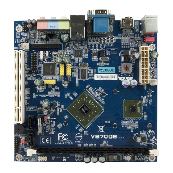
- Page 11 User Manual Lists of Figures Figure 1: Layout diagram of the VB7008 mainboard (top view) ......6 Figure 2: Mounting holes and dimensions of the VB7008 mainboard ....7 Figure 3: External I/O port dimensions of the VB7008 mainboard......7 Figure 4: Height distribution of the VB7008 mainboard...........
- Page 12 VB7008 User Manual VB7008 User Manual VB7008 VB7008 User Manual User Manual Figure 32: SATA DOM voltage select jumper............40 Figure 33: DDR3 memory slots ..................41 Figure 34: Unlocking the memory DIMM slot............42 Figure 35: Inserting the memory module..............42 Figure 36: Locking the memory module ..............
- Page 13 Table 25: Composite + S-Video pin header pinout ..........35 Table 26: CLEAR CMOS jumper settings..............37 Table 27: COM2 voltage select jumper settings ............. 39 Table 28: SATA DOM voltage select jumper settings ........... 40 Table 29: VB7008 mating connector vendor lists ........... 93 xiii...
-
Page 14: Product Overview Product Overview
Padlock Security Engine, VIA StepAhead™ Technology Suite, VIA PowerSaver, and VIA CoolStream™ technology. The VIA VB7008 has one 1066 MHz DDR3 DIMM slot that support up to 4 GB memory size. The VIA VB7008 provides support for high fidelity audio with its included VIA VT1708S High Definition Audio codec. -
Page 15: Via Vx900 Msp Chipset
The VIA VB7008 enables companies to slowly roll out upgrades as necessary instead of having to replace everything all at once. This ensures that companies using the VB7008 obtain the maximum benefits from its past investments in PCI expansion cards. -
Page 16: Product Specifications
VB7008 User Manual VB7008 User Manual VB7008 VB7008 User Manual User Manual 1.2. Product Specifications Processor Processor Processor Processor ® VIA C7 -D 1.6 GHz NanoBGA2 Supports 800MHz Front Side Bus 21 mm x 21 mm FCBGA ... - Page 17 VB7008 User Manual VB7008 User Manual VB7008 VB7008 User Manual User Manual 1 x Front panel pin header 1 x CPU fan connector 1 x System fan connector 1 x COM pin header 1 x LPC pin header ...
- Page 18 VB7008 User Manual VB7008 User Manual VB7008 VB7008 User Manual User Manual System Monitoring & Management System Monitoring & Management System Monitoring & Management System Monitoring & Management Wake-on-LAN Keyboard and Mouse Power-on Timer Power-on System voltage monitoring ...
-
Page 19: Layout Diagram
SMBus pin header Figure Figure Figure Figure 1 1 1 1 : Layout diagram of the : Layout diagram of the : Layout diagram of the : Layout diagram of the VB7008 VB7008 VB7008 VB7008 mainboard mainboard mainboard (top view) mainboard... -
Page 20: Product Dimensions
170.00 mm 4.97 mm 6.17 mm 6.35 mm Figure Figure 2 2 2 2 : Mounting holes and dimensions of the : Mounting holes and dimensions of the VB7008 VB7008 mainboard mainboard Figure Figure : Mounting holes and dimensions of the... -
Page 21: Height Distribution
1.5. Height Distribution Height: 32.00 mm Height: 33.00 mm Height: 34.80 mm Figure Figure 4 4 4 4 : Height distribution of the : Height distribution of the VB7008 VB7008 mainboard mainboard Figure Figure : Height distribution of the : Height distribution of the... -
Page 22: I/O Interface
2. 2. 2. 2. I/O Interface I/O Interface I/O Interface I/O Interface The VIA VB7008 has a wide selection of interfaces integrated into the board. It includes a selection of frequently used ports as part of the external I/O coastline. 2.1. External I/O Ports... -
Page 23: Ps/2 Port
VB7008 User Manual VB7008 User Manual VB7008 VB7008 User Manual User Manual 2.1.1. PS/2 Port The mainboard has two integrated PS/2 ports for keyboard and mouse. Each port is using the 6-pin Mini-DIN connector. The color purple is use for a PS/2 keyboard while the color green is use for a PS/2 mouse. - Page 24 VB7008 User Manual VB7008 User Manual VB7008 VB7008 User Manual User Manual TX0- TXC+ Ground TXC- DDCSCL DDCSDA Ground Hot Plug Detect ® ® ® ® Table Table Table Table 2 2 2 2 : HDMI : HDMI : HDMI...
-
Page 25: Vga Port
VB7008 User Manual VB7008 User Manual VB7008 VB7008 User Manual User Manual 2.1.3. VGA Port The integrated 15-pin VGA port uses a female DE-15 connector. The VGA port is for connecting to analog displays. The pinout of the VGA port is shown below. -
Page 26: Com Port
VB7008 User Manual VB7008 User Manual VB7008 VB7008 User Manual User Manual 2.1.4. COM Port The integrated 9-pin COM port uses a male DE-9 connector. The COM (COM1) port supports the RS-232 standard. The pinout of the COM port is shown below. -
Page 27: Usb 2.0 Port
User Manual 2.1.5. USB 2.0 Port There are two integrated USB 2.0 ports in VB7008 mainboard. The USB- interface port gives complete Plug and Play and hot swap capability for external devices and it complies with USB UHCI, rev. 2.0. Each USB port is using the USB Type A receptacle connector. -
Page 28: Rj45 Lan Port: Gigabit Ethernet
VB7008 User Manual VB7008 User Manual VB7008 VB7008 User Manual User Manual 2.1.6. RJ45 LAN port: Gigabit Ethernet The integrated 8-pin Gigabit Ethernet port is using an 8 Position 8 Contact (8P8C) receptacle connector (commonly referred to as RJ45). The pinout of the Gigabit Ethernet port is shown below. -
Page 29: Audio Ports
VB7008 User Manual VB7008 User Manual VB7008 VB7008 User Manual User Manual 2.1.7. Audio Ports There are three audio jack receptacles integrated into a single stack on the I/O coastline. Each receptacle can fit a 3.5 mm Tip Ring Sleeve (TRS) connector to enable connections to Line-Out Line-In, and MIC-in. -
Page 30: Onboard Connectors
VB7008 User Manual VB7008 User Manual VB7008 VB7008 User Manual User Manual 2.2. Onboard Connectors 2.2.1. ATX Power Connector The mainboard has a 20-pin ATX power connector onboard. The ATX power connector is labeled as “ATX_POWER1”. The pinout of the ATX power connector is shown below. -
Page 31: Cmos Battery Slot
VB7008 User Manual VB7008 User Manual VB7008 VB7008 User Manual User Manual 2.2.2. CMOS Battery Slot The mainboard is equipped with a CMOS battery slot, which is compatible with CR2032 coin batteries. The CMOS battery slot is labeled as “BAT2”. -
Page 32: Front Panel Pin Header
VB7008 User Manual VB7008 User Manual VB7008 VB7008 User Manual User Manual 2.2.3. Front Panel Pin Header The front panel pin header consists of 15 pins in a 16-pin block. Pin 15 is keyed. The front panel pin header is labeled as “F_PANEL1”. It provides access to system LEDs, power, reset, system speaker and HDD LED. -
Page 33: Smbus Pin Header
VB7008 User Manual VB7008 User Manual VB7008 VB7008 User Manual User Manual 2.2.4. SMBus Pin Header The SMBus pin header consists of three pins that allow connecting the SMBus devices. Devices communicate with a SMBus host and/or other SMBus devices using the SMBus interface. - Page 34 VB7008 User Manual VB7008 User Manual VB7008 VB7008 User Manual User Manual CPU fan fan (C (C (C (CPUFAN1 PUFAN1 PUFAN1) ) ) ) PUFAN1 SYSFAN1 Signal Signal Signal Signal FANIN1 CPUFAN1 FANCTL Ground System fan System fan (SYSFAN1 (SYSFAN1) ) ) )
-
Page 35: Sata Connectors
VB7008 User Manual VB7008 User Manual VB7008 VB7008 User Manual User Manual 2.2.6. SATA Connectors The two SATA connectors on board can support up to 3 Gb/s transfer speeds. The SATA connectors are labeled as “SATA1” and “SATA2”. The pinout of the SATA connectors are shown below. -
Page 36: Usb 2.0 Pin Headers
VB7008 User Manual VB7008 User Manual VB7008 VB7008 User Manual User Manual 2.2.7. USB 2.0 Pin Headers The mainboard has three USB 2.0 pin header blocks that support up to six USB 2.0 ports. The pin header blocks are labeled as “USB_2”, USB_3, and “USB_4”. - Page 37 VB7008 User Manual VB7008 User Manual VB7008 VB7008 User Manual User Manual USB_ USB_4 4 4 4 USB_ USB_ Signal Signal Signal Signal Signal Signal Signal Signal VUSB6 VUSB6 USBD_T6- USB_T7- USBD_T6+ USB_T7+ Ground Ground Ground Table Table Table Table 15...
-
Page 38: Com Pin Header
VB7008 User Manual VB7008 User Manual VB7008 VB7008 User Manual User Manual 2.2.8. COM Pin Header The mainboard include one onboard COM pin header in addition to the COM port 1 on the external I/O. The onboard COM pin header labeled as “COM2”... -
Page 39: Ps/2 Keyboard And Mouse Pin Header
VB7008 User Manual VB7008 User Manual VB7008 VB7008 User Manual User Manual 2.2.9. PS/2 Keyboard and Mouse Pin Header The mainboard has a pin header for a PS/2 keyboard and mouse. The pin header is labeled as “KBMS1”. The pinout of the pin header is shown below. -
Page 40: Front Audio Pin Header
VB7008 User Manual VB7008 User Manual VB7008 VB7008 User Manual User Manual 2.2.10. Front Audio Pin Header In addition to the TRS audio jacks on the external I/O coastline, the mainboard has a pin header for Line-Out and MIC-In. The pin header is labeled as “F_AUDIO1”. -
Page 41: Spdif Connector
VB7008 User Manual VB7008 User Manual VB7008 VB7008 User Manual User Manual 2.2.11. SPDIF Connector The mainboard has one 3-pin SPDIF (Sony Philips Digital Interface) connector. The SPDIF output provides digital audio to external speakers or compressed AC3 data to an external Dolby Digital Decoder. The connector is labeled as “SPDIF1”. -
Page 42: Spi Pin Header
VB7008 User Manual VB7008 User Manual VB7008 VB7008 User Manual User Manual 2.2.12. SPI Pin Header The mainboard has one 8-pin SPI pin header. The SPI (Serial Peripheral Interface) pin-header is used to connect to the SPI BIOS programming fixture. -
Page 43: Lpc Pin Header
VB7008 User Manual VB7008 User Manual VB7008 VB7008 User Manual User Manual 2.2.13. LPC Pin Header The mainboard has one LPC pin header for connecting LPC devices. The pin header is labeled as “LPC”. The pinout of the pin header is shown below. -
Page 44: Lpt Pin Header
VB7008 User Manual VB7008 User Manual VB7008 VB7008 User Manual User Manual 2.2.14. LPT Pin Header The mainboard has one LPT pin header for connecting 25-pin LPT female external connector for parallel port. A parallel port is a standard printer port that supports Enhanced Parallel Port (EPP) and Extended Capabilities Parallel Port (ECP) modes. - Page 45 VB7008 User Manual VB7008 User Manual VB7008 VB7008 User Manual User Manual -LP_ACK Ground LP_BUSY Ground LP_PE Ground LP_SLCT Table Table 22 22: LPT pin header pinout : LPT pin header pinout Table Table 22 22 : LPT pin header pinout...
-
Page 46: Sir Pin Header
VB7008 User Manual VB7008 User Manual VB7008 VB7008 User Manual User Manual 2.2.15. SIR Pin Header The mainboard has SIR (Serial Infrared) pin header. This pin header is used to connect to a serial infrared module. The pin header is labeled as “SIR1”. The pinout of the SIR pin header is shown below. -
Page 47: Temperature Sensor Pin Header
VB7008 User Manual VB7008 User Manual VB7008 VB7008 User Manual User Manual 2.2.16. Temperature Sensor Pin Header The mainboard supports a pin header (3-pin) that allows the connection of a temperature sensor cable for detecting the system’s internal air temperature. -
Page 48: Composite + S-Video Out Pin Header (Optional)
VB7008 User Manual VB7008 User Manual VB7008 VB7008 User Manual User Manual 2.2.17.Composite + S-Video Out Pin Header (optional) The mainboard provide an optional Composite + S-Video out pin header that allows connecting the TV port/jack connector in order to interface TV monitor or S-Video device to the mainboard. -
Page 50: Jumpers
VB7008 User Manual VB7008 User Manual VB7008 VB7008 User Manual User Manual 3. 3. 3. 3. Jumpers Jumpers Jumpers Jumpers 3.1. Clear CMOS Jumper The onboard CMOS RAM stores system configuration data and has an onboard battery power supply. To reset the CMOS settings, set the jumper on pins 2 and 3 while the system is off. - Page 51 VB7008 User Manual VB7008 User Manual VB7008 VB7008 User Manual User Manual Note: Note: Note: Note: Except when clearing the RTC RAM, never remove the cap from the CLEAR_CMOS jumper default position. Removing the cap will cause system boot failure. Avoid clearing the CMOS while the system...
-
Page 52: Com2 Voltage Select Jumper
VB7008 User Manual VB7008 User Manual VB7008 VB7008 User Manual User Manual 3.2. COM2 Voltage Select Jumper The additional COM port (available through the onboard COM2 pin header, see page 25) can support both +5V and +12V. The COM2 voltage select pin jumper is a selector to determine the input voltage of COM2 pin header connector. -
Page 53: Sata Dom Voltage Select Jumper
VB7008 User Manual VB7008 User Manual VB7008 VB7008 User Manual User Manual 3.3. SATA DOM Voltage Select Jumper The SATA2 connector (see page 22) can be used to support Disk-on-Module (DOM) flash drive. When the jumper is set, +5V will be delivered to the 7 pin of the SATA2 connector. -
Page 54: Expansion Slots
VB7008 User Manual VB7008 User Manual VB7008 VB7008 User Manual User Manual 4. 4. 4. 4. Expansion Slots Expansion Slots Expansion Slots Expansion Slots 4.1. DDR3 Memory Slots The mainboard provide one DDR3 DIMM memory slot. The memory slot can accommodate up to 4 GB of 1066 MHz memory. -
Page 55: Installing A Memory Module
VB7008 User Manual VB7008 User Manual VB7008 VB7008 User Manual User Manual 4.1.1. Installing a Memory Module Step 1 Step 1 Step 1 Step 1 Disengage the locking mechanism at both ends of the DIMM slot by pressing the retaining clips outward. - Page 56 VB7008 User Manual VB7008 User Manual VB7008 VB7008 User Manual User Manual Step Step 3 3 3 3 Step Step Insert the DIMM memory module into the slot and push down at both ends until the locking clips lock the DIMM memory module into place.
-
Page 57: Removing A Memory Module
VB7008 User Manual VB7008 User Manual VB7008 VB7008 User Manual User Manual 4.1.2. Removing a Memory Module Step 1 Step 1 Step 1 Step 1 To disengage the locking clips, push outward the locking clips on both ends of memory slot. When the locking clips have cleared, the DIMM memory module will automatically pop up. -
Page 58: Pci Slot
VB7008 User Manual VB7008 User Manual VB7008 VB7008 User Manual User Manual 4.1.3. PCI Slot The onboard PCI slot, labeled as “PCI_SLOT1”, supports 5V 32-bit PCI cards. It is not compatible with PCI cards requiring 3.3V signaling. The location of the PCI slot is shown below. -
Page 60: Hardware Installation Hardware Installation
Hardware Installation 5.1. Installing into a Chassis The VB7008 can be fitted into any chassis that has the mounting holes for compatible with the standard Mini-ITX mounting hole locations. Additionally, the chassis must meet the minimum height requirements for specified areas of the mainboard. -
Page 61: Suggested Minimum Chassis Height
VB7008 User Manual VB7008 User Manual VB7008 VB7008 User Manual User Manual coastline should have a buffer of at least 5.00 mm. The two sides adjacent to the I/O coastline should have at least a 10.00 mm buffer. For the side that is close to the PCI slot, the buffer should be at least 100.00 mm if a riser card module will be used. -
Page 62: Suggested Keepout Areas
VB7008 User Manual VB7008 User Manual VB7008 VB7008 User Manual User Manual 5.1.3. Suggested keepout areas The figure below shows the areas of the mainboard that is highly suggested to leave unobstructed. Keep out area Figure Figure 41 41: Suggested keepout areas... - Page 63 VB7008 User Manual VB7008 User Manual VB7008 VB7008 User Manual User Manual...
-
Page 64: Bios Setup Utility
VB7008 User Manual VB7008 User Manual VB7008 VB7008 User Manual User Manual 6. 6. 6. 6. BIOS Setup Utility BIOS Setup Utility BIOS Setup Utility BIOS Setup Utility 6.1. Entering the BIOS Setup Utility Power on the computer and press Delete... -
Page 65: Navigating The Bios Menus
VB7008 User Manual VB7008 User Manual VB7008 VB7008 User Manual User Manual 6.3. Navigating the BIOS Menus Left>/<Right Right> The main menu displays all the BIOS setup categories. Use the <Left Left Left Right Right and <Up Up>/<Down Down> arrow keys to select any item or sub-menu. Descriptions... -
Page 66: Main Menu
VB7008 User Manual VB7008 User Manual VB7008 VB7008 User Manual User Manual 6.5. Main Menu The Main Menu contains thirteen setup functions and two exit choices. Use arrow keys to select the items and press <Enter Enter> to accept or enter Sub-menu. -
Page 67: Pnp/Pci Configurations
VB7008 User Manual VB7008 User Manual VB7008 VB7008 User Manual User Manual Use this menu to set onboard power management functions. 6.5.6. PnP/PCI Configurations Use this menu to set the PnP and PCI configurations. 6.5.7. PC Health Status This menu shows the PC health status. -
Page 68: Standard Cmos Features
VB7008 User Manual VB7008 User Manual VB7008 VB7008 User Manual User Manual 6.6. Standard CMOS Features Phoenix - AwardBIOS CMOS Setup Utility Standard CMOS Features Item Help Date (mm:dd:yy) Mon, Aug 15 2011 Time (hh:mm:ss) 3 : 17 : 8... -
Page 69: Ide Channels
VB7008 User Manual VB7008 User Manual VB7008 VB7008 User Manual User Manual 6.7. IDE Channels Channel 0 Master Channel 0 Master Channel 0 Master Channel 0 Master Phoenix - AwardBIOS CMOS Setup Utility IDE Channel 0 Master Item Help IDE HDD Auto-Detection... - Page 70 VB7008 User Manual VB7008 User Manual VB7008 VB7008 User Manual User Manual The specifications of your drive must match with the drive table. The hard disk will not work properly if you enter incorrect information in this category. Select “Auto”...
-
Page 71: Advanced Bios Features
VB7008 User Manual VB7008 User Manual VB7008 VB7008 User Manual User Manual 6.8. Advanced BIOS Features Phoenix - AwardBIOS CMOS Setup Utility Advanced BIOS Features Hard Disk Boot Priority [Press Enter] Item Help Quick Power On Self Test [Enabled] First Boot Device... -
Page 72: Boot Other Device
VB7008 User Manual VB7008 User Manual VB7008 VB7008 User Manual User Manual 6.8.3. Boot Other Device Enables the system to boot from alternate devices if the system fails to boot from the “First/Second/Third Boot Device” lists. Settings Settings Description Description... -
Page 73: Hard Disk Boot Priority
VB7008 User Manual VB7008 User Manual VB7008 VB7008 User Manual User Manual 6.9. Hard Disk Boot Priority Phoenix - AwardBIOS CMOS Setup Utility Hard Disk Boot Priority Item Help 1. Bootable Add-in Cards Menu Level Use < > or <... -
Page 74: Advanced Chipset Features
VB7008 User Manual VB7008 User Manual VB7008 VB7008 User Manual User Manual 6.10. Advanced Chipset Features Phoenix - AwardBIOS CMOS Setup Utility Advanced Chipset Features Item Help PCIE Bus Control [Press Enter] UMA & P2P Bridge Control [Press Enter] CPU & PCI Bus Control... -
Page 75: Pcie Bus Control
VB7008 User Manual VB7008 User Manual VB7008 VB7008 User Manual User Manual 6.11. PCIE Bus Control Phoenix - AwardBIOS CMOS Setup Utility PCIE Bus Control PCIE Root Port [Enable] Item Help PCIE Target Link Speed [Auto] Menu Level : Move... -
Page 76: Uma & P2P Bridge Control
VB7008 User Manual VB7008 User Manual VB7008 VB7008 User Manual User Manual 6.12. UMA & P2P Bridge Control Phoenix - AwardBIOS CMOS Setup Utility UMA & P2P Bridge Control UMA Enable [Enable] Item Help VGA Share Memory Size [256M] CPU Direct Access FB... -
Page 77: Select Display Device
VB7008 User Manual VB7008 User Manual VB7008 VB7008 User Manual User Manual 6.12.4. Select Display Device This setting refers to the type of display being used with the system. Settings: [Auto, Manual] 6.12.5. Select Display Device 1 This setting refers to the type of display device 1 being used with the system. -
Page 78: Cpu & Pci Bus Control
VB7008 User Manual VB7008 User Manual VB7008 VB7008 User Manual User Manual 6.13. CPU & PCI Bus Control Phoenix - AwardBIOS CMOS Setup Utility CPU & PCI Bus Control Item Help PCI Master 0 WS Write [Enabled] PCI Delay Transaction... -
Page 79: Integrated Peripherals
VB7008 User Manual VB7008 User Manual VB7008 VB7008 User Manual User Manual 6.14. Integrated Peripherals Phoenix - AwardBIOS CMOS Setup Utility Integrated Peripherals Item Help VIA OnChip IDE Device [Press Enter] VIA OnChip PCI Device [Press Enter] SuperIO Device [Press Enter]... -
Page 80: Via Onchip Ide Device
VB7008 User Manual VB7008 User Manual VB7008 VB7008 User Manual User Manual 6.15. VIA OnChip IDE Device Phoenix - AwardBIOS CMOS Setup Utility VIA OnChip IDE Device Item Help OnChip SATA [Enabled] Menu Level : Move Enter: Select +/-/PU/PD: Value... -
Page 81: Via Onchip Pci Device
VB7008 User Manual VB7008 User Manual VB7008 VB7008 User Manual User Manual 6.16. VIA OnChip PCI Device Phoenix - AwardBIOS CMOS Setup Utility VIA OnChip PCI Device Item Help Onboard PCIE LAN [Enabled] Onboard LAN Boot ROM [Disabled] OnChip HDAC Device... -
Page 82: Superio Device
VB7008 User Manual VB7008 User Manual VB7008 VB7008 User Manual User Manual 6.17. SuperIO Device Phoenix - AwardBIOS CMOS Setup Utility SuperIO Device Item Help Onboard Serial Port 1 [3F8/IRQ4] Onboard Serial Port 2 [2F8/IRQ3] SIR Function Setting [Disabled] Menu Level... -
Page 83: Ecp Mode Use Dma
VB7008 User Manual VB7008 User Manual VB7008 VB7008 User Manual User Manual ECP mode. Choosing ECP + EPP will allow the onboard parallel port to support both the ECP and EPP modes simultaneously. Settings: [SPP, EPP, ECP, ECP + EPP] 6.17.6. -
Page 84: Usb Device Setting
VB7008 User Manual VB7008 User Manual VB7008 VB7008 User Manual User Manual 6.18. USB Device Setting Phoenix - AwardBIOS CMOS Setup Utility USB Device Setting Item Help USB 1.0 Controller [Enabled] USB 2.0 Controller [Enabled] USB Operation Mode [High Speed]... -
Page 85: Usb Mouse Function
VB7008 User Manual VB7008 User Manual VB7008 VB7008 User Manual User Manual Settings: [Disabled, Enabled] 6.18.5. USB Mouse Function Settings: [Disabled, Enabled] 6.18.6. USB Storage Function Enable or disable legacy support of USB mass storage. Settings: [Disabled, Enabled]... -
Page 86: Power Management Setup
VB7008 User Manual VB7008 User Manual VB7008 VB7008 User Manual User Manual 6.19. Power Management Setup Phoenix - AwardBIOS CMOS Setup Utility Power Management Setup Item Help EuP/ErP Lot6 [Disabled] ACPI Suspend Type [S1&S3] Soft-Off by PWRBTN [Instant-Off] Menu Level... -
Page 87: Run Vgabios If S3 Resume
VB7008 User Manual VB7008 User Manual VB7008 VB7008 User Manual User Manual Delay 4 Sec System is turned off if power button is pressed for more than four seconds. Instant-Off Power button functions as a normal power-on/-off button. 6.19.4. Run VGABIOS if S3 Resume Select whether to run VGA BIOS if resuming from S3 state. -
Page 88: Wakeup Event Detect
VB7008 User Manual VB7008 User Manual VB7008 VB7008 User Manual User Manual 6.20. Wakeup Event Detect Phoenix - AwardBIOS CMOS Setup Utility Wakeup Event Detect Item Help PS2KB Wakeup Select [Hot Key] PS2KB Wakeup Key Select [Any Key] PS2MS Wakeup Key Select... -
Page 89: Ps2 Mouse Power On
VB7008 User Manual VB7008 User Manual VB7008 VB7008 User Manual User Manual 6.20.5. PS2 Mouse Power ON Settings: [Disabled, Enabled] 6.20.6. RTC Alarm Resume Set a scheduled time and/or date to automatically power on the system. Settings: [Disabled, Enabled] 6.20.7. -
Page 90: Pnp/Pci Configurations
VB7008 User Manual VB7008 User Manual VB7008 VB7008 User Manual User Manual 6.21. PnP/PCI Configurations Phoenix - AwardBIOS CMOS Setup Utility PnP/PCI Configurations Item Help Init Display First [Onboard] Reset Configuration Data [Disabled] Menu Level Resources Controlled By [Auto(ESCD)] IRQ Resources... - Page 91 VB7008 User Manual VB7008 User Manual VB7008 VB7008 User Manual User Manual Settings Settings Description Description Settings Settings Description Description Auto(ESCD) BIOS will automatically assign IRQ, DMA and memory base address fields Manual Unlocks “IRQ Resources” for manual configuration...
-
Page 92: Pc Health Status
VB7008 User Manual VB7008 User Manual VB7008 VB7008 User Manual User Manual 6.22 PC Health Status Phoenix - AwardBIOS CMOS Setup Utility PC Health Status VCore 1.000V Item Help 5.100V +3.3V 3.200V Menu Level +12V 11.880V VSB3V 3.360V Voltage Battery 3.232V... -
Page 93: Frequency/Voltage Control
VB7008 User Manual VB7008 User Manual VB7008 VB7008 User Manual User Manual 6.23 Frequency/Voltage Control Phoenix - AwardBIOS CMOS Setup Utility Frequency/Voltage Control Item Help Current FSB Frequency 100 MHz Current DRAM Frequency 533 MHz DRAM Clock [By SPD] Menu Level... - Page 94 VB7008 User Manual VB7008 User Manual VB7008 VB7008 User Manual User Manual function reduces the EMI generated by modulating the pulses so that the spikes of the pulses are reduced to flatter curves. Settings: [Disabled, +/- 0.1%, +/- 0.2%, +/- 0.3%, +/- 0.4%, +/- 0.5%, +/- 0.6%,...
-
Page 95: Load Optimized Defaults
VB7008 User Manual VB7008 User Manual VB7008 VB7008 User Manual User Manual 6.24 Load Optimized Defaults Phoenix - AwardBIOS CMOS Setup Utility Standard CMOS Features Frequency/Voltage Control Advanced BIOS Features Load Optimized Defaults Advanced Chipset Features Set Supervisor Password Integrated Peripherals... -
Page 96: Set Supervisor/User Password
VB7008 User Manual VB7008 User Manual VB7008 VB7008 User Manual User Manual 6.25 Set Supervisor/User Password Phoenix - AwardBIOS CMOS Setup Utility Standard CMOS Features Frequency/Voltage Control Advanced BIOS Features Load Optimized Defaults Advanced Chipset Features Set Supervisor Password Integrated Peripherals... - Page 97 VB7008 User Manual VB7008 User Manual VB7008 VB7008 User Manual User Manual Additionally, when a password is enabled, the BIOS can be set to request the password each time the system is booted. This would prevent unauthorized use of the system. See “Security Option” in the “Advanced BIOS Features”...
-
Page 98: Save & Exit Setup
VB7008 User Manual VB7008 User Manual VB7008 VB7008 User Manual User Manual 6.26 Save & Exit Setup Phoenix - AwardBIOS CMOS Setup Utility Standard CMOS Features Frequency/Voltage Control Advanced BIOS Features Load Optimized Defaults Advanced Chipset Features Set Supervisor Password... -
Page 99: Exit Without Saving
VB7008 User Manual VB7008 User Manual VB7008 VB7008 User Manual User Manual 6.27 Exit Without Saving Phoenix - AwardBIOS CMOS Setup Utility Standard CMOS Features Frequency/Voltage Control Advanced BIOS Features Load Optimized Defaults Advanced Chipset Features Set Supervisor Password Integrated Peripherals... -
Page 100: Driver Installation
For embedded operating systems, the related drivers can be found in the VIA Embedded website at www.viaembedded.com. 7.2 Linux Driver Support The VIA VB7008 mainboard is highly compatible with many Linux distributions. Support and drivers are provided through various methods including: Drivers provided by VIA Using a driver built into a distribution package Visiting www.viaembedded.com for the latest updated drivers... -
Page 102: Appendix A. Power Consumption Report
Power Consumption Report Power Consumption Report Power Consumption Report Power Consumption Report Power consumption tests were performed on the VIA VB7008. The following tables represent the breakdown of the voltage, amp and wattage values while running common system applications. A.1. VB7008-16 The tests were performed based on the following additional components: ®... -
Page 103: Playing Mp3-Media Player
VB7008 User Manual VB7008 User Manual VB7008 VB7008 User Manual User Manual A.1.2. Playing MP3-Media Player Power Plane Power Plane Power Plane Power Plane Volts Volts Volts Volts Amperes Amperes Amperes Amperes Watts Watts Watts Watts +3.3V 2.761 0.908 2.507 4.737... -
Page 104: Run Burn-In Test V6.0
VB7008 User Manual VB7008 User Manual VB7008 VB7008 User Manual User Manual A.1.5. Run Burn-in Test V6.0 Power Plane Power Plane Power Plane Power Plane Volts Volts Volts Volts Amperes Amperes Amperes Amperes Watts Watts Watts Watts +3.3V 2.897 0.881 2.552... -
Page 106: Appendix B. Mating Connector Vendor Lis
Mating Connector Mating Connector Mating Connector Vendor Lists Vendor Lists Vendor Lists Vendor Lists The following tables listed the mating connector vendor lists of VB7008 mainboard. Connectors Connectors Part No. Part No. Mating Vendor & P/N Mating Vendor & P/N... - Page 107 Taiwan Headquarters Europe 1F, 531 Zhong-Zheng Road 940 Mission Court In den Dauen 6 Xindian District, New Taipei City 231, Fremont, CA 94539 53117 Bonn Taiwan Germany TEL: 886.2.2218.5452 TEL: 1.510.683.3300 TEL: 49.228.688565.0 FAX: 886.2.2218.5453 FAX: 1.510.687.4654 FAX: 49.228.688565.19 Email: embedded@via.com.tw Email: embedded@viatech.com Email: embedded@via-tech.de China...
Need help?
Do you have a question about the VB7008 and is the answer not in the manual?
Questions and answers