Icom IC-PCR1500 Instruction Manual
Icom ic-pcr1500 communication receiver: instruction manual
Hide thumbs
Also See for IC-PCR1500:
- Service manual (68 pages) ,
- Service manual (7 pages) ,
- Instruction manual (77 pages)
Table of Contents
Advertisement
Advertisement
Table of Contents

Subscribe to Our Youtube Channel
Related Manuals for Icom IC-PCR1500


Summary of Contents for Icom IC-PCR1500
- Page 1 INSTRUCTION MANUAL COMMUNICATIONS RECEIVER iPCR1500 iPCR2500...
-
Page 2: Important
FOREWORD IMPORTANT READ ALL INSTRUCTIONS Thank you for purchasing this Icom radio. The IC-PCR1500/ carefully and completely PCR2500 is designed and built before using the receiver. COMMUNICATIONS RECEIVERS with Icom’s state of the art technology and craftsmanship. With SAVE THIS INSTRUCTION MANUAL—... -
Page 3: System Requirements
SYSTEM REQUIREMENTS SUPPLIED ACCESSORIES ® ® • Microsoft Windows XP/2000/Me/98SE installed • USB 2.0 or 1.1 ® ® • Intel Pentium III 450 MHz or faster (Pentium 4 recom- mended) • At least 128 MB of memory or higher (256 MB or more rec- ommended) •... -
Page 4: Precautions
Main unit power OFF or disconnect the If a connection cable is disconnected or has a loose connec- USB cable between the Main unit and PC while IC-PCR1500 tion during operation, an error may occur. Connect the con- or IC-PCR2500 control software is running. -
Page 5: About Apco Project 25
#5,701,390, #5,715,365, #5,649,050, #5,630,011, #5,581,656, The content of this manual, the hardware and software asso- #5,517,511, #5,491,772, #5,247,579, #5,226,084, #5,195,166. ciated with the IC-PCR1500/PCR2500, and the appearance of the IC-PCR1500/PCR2500 are all subject to change with- out notice. For U.S.A. only CAUTION: P25 digital mode is available when optional UT-122 Changes or modifications to this device, not ex-... -
Page 6: Table Of Contents
TABLE OF CONTENTS FOREWORD …………………………………………… i 4 PANEL DESCRIPTION ……………………… 30–43 IMPORTANT …………………………………………… i Application screens …………… 30 (on PC screen) EXPLICIT DEFINITIONS ……………………………… i Main unit ………………………………………… 42 MOUSE PROPERTY SETTING ……………………… i 5 BASIC RECEIVE FUNCTIONS …………… 44–67 SYSTEM REQUIREMENTS …………………………... -
Page 7: Table Of Contents
TABLE OF CONTENTS (Continued) IF shift function ………………………………… 61 Memory/bank scan …………………………… 86 Weather channel operation Versatile memory scan ………………………… 88 ……………… 62 Scan resume condition ………………………… 90 (USA and CANADA versions only) Squelch delay setting ………………………… 63 Scan speed setting …………………………… 91 Single band/Dualwatch operation 8 PRIORITY SCAN ………………………………... -
Page 8: Ut-122 Installation
TABLE OF CONTENTS (Continued) Audio setting screen ………………………… 106 UT-122 installation Multi channel monitor ………………………… 110 ……………………… 128 (IC-PCR2500/R2500 only) Recording operation ………………………… 112 15INTERNAL AUDIO SWITCH ………………… 129 Sampling Rate setting ……………………… 114 16USB PORT SETTING ………………………… 130 Remote recording function …………………... -
Page 9: Hardware Installation
USB remove the antenna holder once it has been taped into cable other than the one supplied by Icom in the original place. Icom Inc cannot accept any responsibility for any IC-PCR1500 or IC-PCR2500 package. -
Page 10: Tnc Connection
INSTALLATION TNC connection DC power supply connection The IC-PCR1500/PCR2500 can receive 9600 bps packet Use a 12 V DC power supply with at least 1.2 A capacity. communication (AFSK) with the use of a TNC (not supplied). Make sure the ground terminal of the DC power supply is Connect the TNC (Terminal Node Controller) as illustrated grounded. -
Page 11: Accessory Attachments
INSTALLATION Accessory attachments D Foot pad Attach 4 foot pads to the bottom of the IC-PCR1500/ PCR2500 as below. IC-PCR2500 Foot pad Detach 4 foot pads from the foot pad sheet. Foot pad sheet (supplied) D Cable hanger The cable hanger is convenient for fixing a cable to the wall, etc. -
Page 12: Driver Installation
CAUTION: Icom Inc. assumes no responsibility for the receiver’s operation resulting from the use of any other USB cable other than the one supplied by Icom in the original IC-PCR1500 or IC-PCR2500 package. e Insert the CD into the appropriate CD drive. - Page 13 DRIVER INSTALLATION ySelect “Search for the best driver in these locations.” then u Click “ ” of the CD drive folder in “My Computer.” select “Include this location in the search,” click [Browse]. • The CD drive folder name (e.g. “D”) is depending on a PC. Select Click Click...
- Page 14 DRIVER INSTALLATION o Click [Next>]. !1 A fter the driver is found, the “Hardware Installation” dialog box appears as below. Click [Continue Anyway] to start the installation. Click Click !2 Windows starts installing the USB driver. !0 T he Wizard starts searching for the driver and shows the dialog below during search.
- Page 15 DRIVER INSTALLATION !3 After the installation is completed, click [Finish]. !5 S elect “Search for the best driver in these locations.” then select “Include this location in the search:”, click [Browse]. Select Click Select Click !4 T he “Found New Hardware Wizard” will come up again to install the USB serial port driver.
- Page 16 DRIVER INSTALLATION !7 C lick “ ” of the “Driver” folder in the CD drive folder, then !9 T he Wizard starts searching for the driver and shows the select “Win” folder. dialog below during search. Click [OK]. Select Click !8 Click [Next>].
- Page 17 DRIVER INSTALLATION @1 Windows starts installing the USB driver. @3 A fter clicking [Finish], the dialog appears as below. @4 Eject the CD. • Restarting the PC is recommended. @2 After the installation is completed, click [Finish]. Click...
-
Page 18: Microsoft ® Windows ® 2000
CAUTION: Icom Inc. assumes no responsibility for the Click receiver’s operation resulting from the use of any other USB cable other than the one supplied by Icom in the original IC-PCR1500 or IC-PCR2500 package. ySelect “Search for a suitable driver for my device (recom- e Insert the CD into the appropriate CD drive. - Page 19 DRIVER INSTALLATION uSelect “Specify a location,” then click [Next>]. o Select the CD drive in “My Computer,” then click [Open]. • The CD drive folder name (e.g. “D”) is depending on a PC. Click No check marks Click Select Click !0 Select the “Driver”...
- Page 20 DRIVER INSTALLATION !1 Select “Win” in the “Driver” folder, then click [Open]. !3 Click [OK]. Click Click Click !4 W hen the driver is found, the following dialog is displayed. Click [Next>] to start the installation. !2 Select “Slabbus” in the “Win” folder, then click [Open]. Click Click Click...
- Page 21 DRIVER INSTALLATION !5 After the installation is completed, click [Finish]. !7 S elect “Search for a suitable driver for my device (recom- mended),” then click [Next>]. Select Click Click !6 T he “Found New Hardware Wizard” appears again. !8 S elect “Specify a location,” then click [Next>]. Click [Next>].
- Page 22 DRIVER INSTALLATION !9 C lick [Browse...]. @1 Select the “Driver” folder in the CD drive, then click [Open]. Click Click Click @0 Select the CD drive in “My Computer,” then click [Open]. • The CD drive folder name (e.g. “D”) is depending on a PC. @2 Select “Win”...
- Page 23 DRIVER INSTALLATION @3 Select “Slabw2k” in the “Win” folder, then click [Open]. @5 W hen the driver is found, the following dialog is displayed. Click [Next>] to start the installation. Click Click Click @4 Click [OK]. Click @6 After the installation is completed, click [Finish]. Click @7 Eject the CD.
-
Page 24: Microsoft Windows 98Se
CAUTION: Icom Inc. assumes no responsibility for the receiver’s operation resulting from the use of any other USB cable other than the one supplied by Icom in the original IC-PCR1500 or IC-PCR2500 package. e Insert the CD into the appropriate CD drive. - Page 25 DRIVER INSTALLATION i Click “ ” of the CD drive folder in “My Computer”. !0 Click [Next>]. • The CD drive folder name (e.g. “D”) is depending on a PC. Click Click !1 W hen the driver is found, the following dialog is displayed. Click [Next>] to start the installation.
- Page 26 DRIVER INSTALLATION !2 After the installation is completed, click [Finish]. !4 S elect “Search for the best driver for your device. (Recom- mended),” then click [Next>]. Select Click Click !3 T he “Add New Hardware Wizard” appears again. Click [Next>]. !5 S elect “Specify a location:”, click [Browse...].
- Page 27 DRIVER INSTALLATION !6 Click “ ” of the CD drive folder in “My Computer.” !8 Click [Next>]. • The CD drive folder name (e.g. “D”) is depending on a PC. Click Click !9 W hen the driver is found, the following dialog is displayed. Click [Next>] to start the installation.
-
Page 28: Microsoft Windows Me
USB cable. CAUTION: Icom Inc. assumes no responsibility for the receiver’s operation resulting from the use of any other USB cable other than the one supplied by Icom in the original IC-PCR1500 or IC-PCR2500 package. Click e Insert the CD into the appropriate CD drive. - Page 29 DRIVER INSTALLATION tThe CP2101 USB device is detected automatically, and the ySelect “Search for the best driver for your device. (Recom- “Add New Hardware Wizard” will come up as below. mended),” then select “Specify a location:”, click [Browse]. Select “Specify the location of the driver (Advanced),” then click [Next>].
- Page 30 DRIVER INSTALLATION i Select “WinMe” in the “Driver” folder, click [OK]. !0 W hen the driver is found, the following dialog is displayed. Click [Next>] to start the installation. Select Click Click o Click [Next>]. !1 After the installation is completed, click [Finish]. Click Click...
- Page 31 DRIVER INSTALLATION !2 T he “Add New Hardware Wizard” appears again. Select !4 Click “ ” of the CD drive folder in “My Computer.” “Specify the location of the driver (Advanced),” then click • The CD drive folder name (e.g. “D”) is depending on a PC. [Next>].
- Page 32 DRIVER INSTALLATION !6 Click [Next>]. !8 After the installation is completed, click [Finish]. Click Click !9 Eject the CD. !7 W hen the driver is found, the following dialog is displayed. • Restarting the PC is recommended. Click [Next>] to start the installation. Click...
-
Page 33: Application Installation
APPLICATION INSTALLATION Installation q Quit all applications when Windows is running. tSelect the display language type from “English” or “Japan- w Insert the CD into the CD drive. ese.” Click [OK]. eOpen the CD drive contents via “My computer” or “Win- dows Explorer.”... - Page 34 • Click [Browse...] then type the desired location if you specifying the installation location. Click Click o Eject the CD. • The IC-PCR1500 2500 shortcut icon is created on the desktop. • The installation starts. • Restarting the PC is recommended.
-
Page 35: Launching The Ic-Pcr1500_2500
APPLICATION INSTALLATION Launching the IC-PCR1500_2500 D Microsoft ® ® D Microsoft ® ® Windows Windows 98SE/Me/2000 qBefore launching the program, please be sure the Main qBefore launching the program, please be sure the Main unit is turned ON. unit is turned ON. •... -
Page 36: Uninstall
APPLICATION INSTALLATION Uninstall rClick the “Icom IC-PCR1500/2500,” then click [Change/Re- In this section, screen shots of Windows XP are used for the instruction example. However, the instructions are similar to move]. the other operating systems, Windows 98SE, Me and 2000. - Page 37 APPLICATION INSTALLATION yAfter the preparation, “Confirm Uninstall” appears, click u After the uninstall is completed, click [Finish]. [OK] to remove the program from the PC. Click • The uninstallation starts. Click...
-
Page 38: Panel Description
The application screen can be seen after the application installation. See page 25 for details. q COMPONENT BUTTON (pgs. 37, 45) IC-PCR2500 IC-PCR1500 Click to display the Component screen. w SIMPLE BUTTON (pgs. 36, 46) Click to display the Simple screen. - Page 39 !1 S ETTING BUTTON For IC-PCR2500 Click to make the DTMF remote commander screen ap- For IC-PCR1500 (pgs. 55, 116) pear/disappear for main band (right button) and sub band Click to make the auto mode setting list, short cut key list (left button).
- Page 40 PANEL DESCRIPTION D [Receiver] (Multi-function receiver) screen $3 b IC-PCR2500 single band operation @3 @4...
- Page 41 PANEL DESCRIPTION q CLOSE BUTTON (p. 46) u AUDIO FREQUENCY GAIN CONTROL [AF GAIN] (p. 52) Click to quit and exit the application screen. Click to adjust the audio output level. • Right-click to increase the audio output level. w MINIMIZE BUTTON •...
- Page 42 PANEL DESCRIPTION !4 IF-SHIFT CONTROL (p. 61) @2 W EATHER ALERT BUTTON [WX] (p. 62) Click to set a signal passband position. Push to start the weather alert function. (USA and • Right-click to increase the signal passband position. CANADA version only) •...
- Page 43 PANEL DESCRIPTION @9 FREQUENCY BUTTON [FREQ] (p. 98) #8 ATTENUATOR BUTTON [ATT] (p. 59) Click to show the receiving signal relative to signal strength Click to turn the ATT (Attenuator) function ON or OFF. • “ATT” appears when the ATT function is turned ON. while sweeping..
- Page 44 PANEL DESCRIPTION $3 b DSQL SETTING BUTTON [DSQL] D Simple screen Click to turn the digital squelch ON or OFF. The Simple screen buttons, controls, etc. operate the same • Available only when DV or P25 mode is selected. as the Multi-function receiver screens. Please refer to the ex- When the digital squelch is turned ON, right-click to planations on pages 33 to 36.
- Page 45 PANEL DESCRIPTION D Component screen The Component screen buttons, controls, etc. operate the same as the Multi-function receiver screens. Please refer to the explanations on pages 33 to 36. #4 #3 $3 b $2 $1 IC-PCR2500 single band operation @1 !9 @3 @4...
- Page 46 PANEL DESCRIPTION D Function display (on Multi-function receiver screen) q TUNING STEP INDICATOR Indicates the tuning step digit. w FREQUENCY READOUT Indicates the receive frequency and data as it is being input such as memory channel numbers, etc. e TUNING STEP INDICATOR (p. 50) This is the frequency increment used when selecting a fre- quency using the tuning dial and when searching for sig- nals using a scan function.
- Page 47 PANEL DESCRIPTION o IF-SHIFT INDICATOR (p. 61) !7 ATTENUATOR INDICATOR [ATT] (p. 59) Indicates the received signal passband position. Appears when the ATT (Attenuator) function is ON. !0 IF-FILTER PASSBAND WIDTH INDICATOR (p. 58) !8 TSQL/DTCS INDICATOR [TSQL]/[DTCS] Indicates the current signal passband width. “TSQL”...
- Page 48 PANEL DESCRIPTION @5 R ECEIVE MODE INDICATORS (p. 54) D Function display (on Simple screen) Indicate the current receive mode. The function display indicators on the Simple screen operate @6 IF FILTER INDICATOR (p. 58) the same as on the Multi-function receiver screens. Please refer to the explanations on pages 38 to 40.
- Page 49 PANEL DESCRIPTION D Function display (on Component screen) The function display indicators on the Component screen op- erate the same as on the Multi-function receiver screens. Please refer to the explanations on pages 38 to 40. !8 !9...
-
Page 50: Main Unit
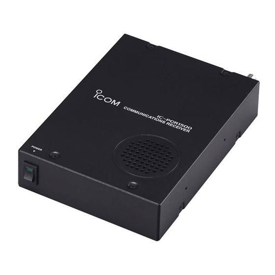
2-conductor 3.5 (d) mm ( ⁄ ˝)/100 kΩ 2-conductor 3.5 (d) mm ( ⁄ ˝)/8 Ω IC-PCR1500 Rear z POWER SWITCH [POWER] Turn the Main unit power ON and OFF. x POWER INDICATOR Lights when the Main unit is turned ON. - Page 51 PANEL DESCRIPTION q ANTENNA CONNECTOR1 [ANT1] y EXTERNAL SPEAKER JACK [EXT SP] Connects a 50 Ω antenna with a BNC connector and a 50 Connects an 8 Ω external speaker. Ω coaxial cable. • Audio output power is more than 0.5 W. w DATA JACK [DATA] u CONTROLLER [CONTROLLER] Connect to a PC via the RS-232 cable (D-sub 9 pin) for data...
-
Page 52: Basic Receive Functions
IC-PCR1500_2500 program. (p. 27) screen. eClick the zPowerx icon on the tool bar to connect the con- IC-PCR1500 trol software and Main unit. rClick the desired icon, zReceiverx, zCompox or zSimplex on the tool bar to select the control screen that you want to use. - Page 53 BASIC RECEIVE FUNCTIONS Click the zCompox icon for the Component screen. IC-PCR1500 IC-PCR2500...
-
Page 54: Closing The Control Screen
BASIC RECEIVE FUNCTIONS Click the zSimplex icon for the Simple screen. Closing the control screen IC-PCR1500 Click the close button ([X]) to close the control screen. • Click the close button (X) in each [TUNING PANEL], [MODE/VOL PANEL], [METER/SCAN PANEL] and [SCOPE PANEL] when the Component screen is displayed. -
Page 55: Receiving
Main unit is turned ON (p. 42). • [Receiver] screen zAF GAINx qClick the zPowerx icon on the tool bar to turn power ON. IC-PCR1500 IC-PCR2500 wClick the desired icon, zReceiverx, zCompox or zSimplex on the tool bar to select the displayed receiver screen type that you want to use. -
Page 56: Setting A Frequency
BASIC RECEIVE FUNCTIONS Setting a frequency D Using the tuning dial Depending on the situation, the receive frequency can be set using the following methods. Frequencies can be set from Click zDIALx to set the receive frequency with the selected 0.010 to 3299.9999 MHz. - Page 57 BASIC RECEIVE FUNCTIONS • [Receiver] screen 10-KEYPAD IC-PCR1500 IC-PCR2500 zDIALx zCEx z•x MAIN zENTx 10-KEYPAD 10-KEYPAD Active band only • [Compo] screen IC-PCR1500 IC-PCR2500 10-KEYPAD zDIALx TUNING MAIN zCEx 10-KEYPAD 10-KEYPAD z•x zENTx Active band only • [Simple] screen IC-PCR1500...
-
Page 58: Setting A Tuning Step
Setting a tuning step When using the tuning dial to change the frequency, or when • [Receiver] screen a scan function is activated, the frequency changes in incre- IC-PCR1500 IC-PCR2500 ments determined by the set tuning step. The tuning step is adjustable. - Page 59 “USER TS Setting...”. You can edit the desired tuning step from 0.001–9999.999 • [Simple] screen kHz (in 0.001 step) directly. IC-PCR1500 IC-PCR2500 *Available only when [Simple] screen is displayed. MAIN Tuning step indication...
-
Page 60: Audio Level Setting
• Push the PC’s [↑] (UP) or [↓] (DOWN) key also sets the audio level. • Push the PC’s [↑] (UP) or [↓] (DOWN) key also sets the audio level. • [Simple] screen • [Receiver] screen IC-PCR1500 IC-PCR2500 IC-PCR1500 IC-PCR2500... -
Page 61: Squelch Level Setting
The squelch function sets a minimum receive signal level below which no audio is sent to the speaker. This prevents • [Receiver] screen static or hiss from being heard through the speaker between IC-PCR1500 IC-PCR2500 transmissions. A higher squelch setting removes weak signals. The remove level is displayed on the S-meter (S-meter squelch). -
Page 62: Receive Mode Selection
BASIC RECEIVE FUNCTIONS Receive mode selection • [Receiver] screen IC-PCR1500 IC-PCR2500 Receive modes are determined by the physical properties of the radio signals. The receiver has 5 receive modes: USB LSB, CW, AM, WFM and FM modes. The mode selection is stored independently in each memory channel. -
Page 63: Automatic Mode Selection
• When inputting a new frequency, other data automatically ap- pears in the other column. • To delete a frequency range setting, enter [0] or [Space] into the IC-PCR1500 [Freq Low] column from the keyboard. tInput the higher frequency of the frequency range into the [Freq High] column, push the [Enter] key. -
Page 64: Monitor Function
Monitor function This function is used to listen to weak signals without disturb- • [Receiver] screen ing the squelch setting or to open the squelch manually even IC-PCR1500 IC-PCR2500 when mute functions such as the tone squelch are in use. zMONIx zMUTEx Click zMONIx to monitor the operating frequency. -
Page 65: Duplex Operation
BASIC RECEIVE FUNCTIONS Duplex operation Duplex communication uses one frequency for transmit, and • [Receiver] screen a different frequency for receive. Generally, duplex is used in IC-PCR1500 IC-PCR2500 communication through a repeater, some utility communica- zMONIx tions, etc. During duplex operation, the transmit station frequency is... -
Page 66: If Filter Selection
Selectable passband width are from 3, 6, 15, 50 and 230 (depending on the selected mode). filter widths. • [Simple] screen • Selectable passband width for each mode. IC-PCR1500 IC-PCR2500 SSB mode : 2.8 kHz or 6 kHz Filter indication CW mode : 2.8 kHz or 6 kHz... -
Page 67: Afc Function
AFC function The AFC (Automatic Frequency Control) function tunes the • [Receiver] screen displayed frequency automatically when an off-center fre- IC-PCR1500 IC-PCR2500 quency is received. It activates in FM mode and IF filter set- ting is 6 or 15 kHz only. -
Page 68: Nb Function
NB function The NB (Noise Blanker) function removes pulse-type noise • [Receiver] screen when USB, LSB, CW or AM mode is selected. Note that the IC-PCR1500 IC-PCR2500 noise blanker is not effective against natural noise such as atmospheric static. zNBx Click z z NBx x to turn the NB (Noise Blanker) function ON or OFF. -
Page 69: Vsc Function
• “VSC” appears when the VSC function is turned ON. wClick zCENTERx to set the shift control to its center posi- tion when there is no interference. • [Receiver] screen • [Receiver] screen IC-PCR1500 IC-PCR2500 IC-PCR1500 IC-PCR2500 zSHIFTx control zVSCx... -
Page 70: Weather Channel Operation (Usa And Canada Versions Only)
NOAA broadcast stations transmit weather alert tones before • [Receiver] screen important weather announcements. When the weather alert IC-PCR1500 IC-PCR2500 function is turned ON, the selected weather channel is moni- tored each 5 sec. for the announcement. When the alert sig- nal is detected, the “WX Alert”... -
Page 71: Squelch Delay Setting
Squelch delay setting Select squelch delay from short and long to prevent repeated • [Receiver] screen opening and closing of the squelch during reception of the IC-PCR1500 IC-PCR2500 same signal. • Short : Short squelch delay. • Long : Long squelch delay. -
Page 72: Single Band/Dualwatch Operation (Ic-Pcr2500 Only)
Main band is activate and Sub band is inhibited. The single band operation’s control screens are similar as the IC-PCR1500. q Click the zSinglex icon on the tool bar to toggle the single band operation or dualwatch operation. - Page 73 BASIC RECEIVE FUNCTIONS • [Compo] screen Dualwatch operation Single band operation • [Simple] screen Dualwatch operation Single band operation...
-
Page 74: Diversity Operation (Ic-Pcr2500 Only)
BASIC RECEIVE FUNCTIONS Diversity operation (IC-PCR2500 only) The diversity receiving function compares the receiving sig- nal strength from two different antennas, ANT1 and ANT2. • [Receiver] screen And it always selects and switches to the strong signal side. This function is useful when you are receiving the signal that the transmitter is moving place and/or you are moving. -
Page 75: Main/Sub Band Selection (Ic-Pcr2500 Only)
BASIC RECEIVE FUNCTIONS Main/Sub band selection (IC-PCR2500 only) Some functions can be set to active band only depending on the control screen. Then you must select the desired band, Main band or sub band, to active band. Click the zMAINx (or zSUBx) icon on the tool bar to toggle the active band as Main band (or Sub band). -
Page 76: Memory Channels
D Memory channel contents memory channel. The following information can be programmed into memory • [Receiver] screen channels: MEMO BANK IC-PCR1500 IC-PCR2500 zYx/zZx zYx/zZx • Memory channel name (p. 73) • Sub name (p. 73) • Operating frequency (p. 48) •... - Page 77 Click zRX Entryx, or right-click a cell then click zRX Entryx in the edit menu. • [Receiver] screen • The selected channel data is displayed on the receiver screen. IC-PCR1500 IC-PCR2500 10-KEYPAD q Select a memory bank. e Click...
-
Page 78: Memory Channel Programming
Memory channel programming 100 memory channels are assigned into a memory bank. • [Receiver] screen There are 26 memory banks. Any of the following information IC-PCR1500 IC-PCR2500 can be stored. • Bank name, memory name, frequency, duplex direction, offset fre- quency, mode, filter, attenuator, tuning step, select memory scan,... - Page 79 CD into the “IC-PCR1500_2500” folder. • [Simple] screen - Right-click the copied file and select [Properties]. Then click IC-PCR1500 IC-PCR2500 [Read-only] check box (no check mark) to cancel the read pro- tection. q Click...
-
Page 80: Editing The Memory List
MEMORY CHANNELS Editing the memory list q Click the zMemory Editx icon on the tool bar to call up the q Select a memory bank. [Memory Channel Editor] screen if it is not displayed. w Click zYx(BANK) or zZx(BANK) to select the desired memory bank. - Page 81 • [Sub Name] (up to 6 characters) is used for the memory name of DV or P25 setting indication does not appear for IC-PCR1500, or for IC-PCR2500 that is depending on version or option installation. the IC-R1500 or IC-R2500’ controller.
- Page 82 MEMORY CHANNELS D Calling up the memory channel data from D Copying a memory contents q Click the zMemory Editx icon on the tool bar to call up the the control screen q Click the zMemory Editx icon on the tool bar to call up the [Memory Channel Editor] screen if it is not displayed.
- Page 83 MEMORY CHANNELS D Memory channel insert/delete D Bank name programming Insert: Each memory bank can be programmed with an alphanu- New blank channels can be inserted into the channel list. meric bank name for easy recognition and can be indicated Channels below the cursor are shifted down automatically.
-
Page 84: Memory Channel Clearing
*Available only when [Simple] screen is displayed. r After selection, click close button ([X]) to close the mem- ory channel list screen. • [Receiver] screen e Click IC-PCR1500 IC-PCR2500 q Click w Select Active band only MEMO zYx/zZx... - Page 85 Click zYx(BANK) or zZx(BANK) to select a memory bank. • [Compo] screen e Right click the cell of the unneeded memory channel to be IC-PCR1500 IC-PCR2500 cleared, then click [Clear] from the displayed menu. r Click [OK] in the displayed dialog box to clear the selected memory channel contents.
-
Page 86: Saving Memory Channel Data
MEMORY CHANNELS Saving memory channel data Creating new memory channel data file The memory channels can be stored as a PC file. Click [Save] or [Save As...] in the [File] menu to back up The new memory channel data file can be created. memory channel data. -
Page 87: Importing A Csv File
MEMORY CHANNELS Importing a CSV file Exporting a CSV file The CSV (Comma Separated Values) format file (which is The selected bank contents are exportable in CSV (Comma saved in CSV format) can be imported and overwrite to the Separated Values) file format. selected bank contents. -
Page 88: Scan Operation
SCAN OPERATION (Multi-function receiver/Component screens only) Scan types Up to 50 programmed scan ranges, memory scan, memory select scan, memory skip scan, mode select memory scan and auto memory write scan provide scanning versatility. MEMORY SCAN PROGRAMMED SCAN Repeatedly scans between Repeatedly scans memory (p. -
Page 89: Programmed Scan
SCAN OPERATION (Multi-function receiver/Component screens only) Programmed scan • [Receiver] screen Programmed scan automatically searches for signals within IC-PCR1500 IC-PCR2500 a specified frequency range. For programmed scan, scan edges must be programmed in advance. D Programming scan edge channels Active band only... - Page 90 SCAN OPERATION (Multi-function receiver/Component screens only) D Skip area setting D Starting a programmed scan qMake sure the squelch is set to the threshold point (closed The skip area setting is available for skipping unwanted fre- quencies that inconveniently stop scanning. condition).
- Page 91 • When the frequency is changed after cancelling a scan and a new scan is activated, scanning starts from the starting frequency of the specified frequency range. When the frequency is not changed, scan starts from the previously stopped frequency. • [Receiver] screen IC-PCR1500 IC-PCR2500 zPROGx zPAUSEx zSTOPx...
-
Page 92: Auto Memory Write Scan
Click wRight-click zAUTOx to call up the [Auto MW Scan] setting screen if it is not displayed. • [Receiver] screen Click to turn the skip area IC-PCR1500 IC-PCR2500 function ON. Active band only zAUTOx Click to clear the Select a memory selected memory bank to be written. - Page 93 SCAN OPERATION (Multi-function receiver/Component screens only) tClick zAUTOx to start auto memory write scan. • “AUTO Scan” blinks and [AUTO] appears while scanning. yTo stop the scan, click zSTOPx or zAUTOx. • [Receiver] screen IC-PCR1500 IC-PCR2500 zAUTOx zPAUSEx zSTOPx Active band only...
-
Page 94: Memory/Bank Scan
SCAN OPERATION (Multi-function receiver/Component screens only) Memory/bank scan This function searches all memory channels in a selected • [Compo] screen memory bank. IC-PCR1500 IC-PCR2500 D Starting a memory/bank scan q Make sure the squelch is set to the threshold point (closed BANK condition). - Page 95 SCAN OPERATION (Multi-function receiver/Component screens only) y Click the zMEMOx button to start memory scan. • “MEMO Scan” blinks and [MEMO] appears while scanning. u To stop the scan, click zSTOPx or zMEMOx. • [Receiver] screen IC-PCR1500 IC-PCR2500 zMEMOx zPAUSEx zSTOPx...
-
Page 96: Versatile Memory Scan
• When selecting the [SKIP] box (memory skip scan), repeatedly • [Receiver] screen scans memory channels except “SKIP” setting is turned ON in IC-PCR1500 IC-PCR2500 memory channel list screen. • When selecting the [MODE SEL] box (mode select memory scan), repeatedly scans all memory channels with the selected operating mode (in [Select Mode] as below). - Page 97 • “MEMO Scan” blinks and [MEMO] appears while scanning. list screen. rTo stop the scan, click zSTOPx or zMEMOx. • At least 2 memory channels must be programmed with the desired condition for scan to proceed. • [Receiver] screen IC-PCR1500 IC-PCR2500 zMEMOx zPAUSEx zSTOPx Active band only...
-
Page 98: Scan Resume Condition
Disappears,’ ‘Delay Volume’ or ‘Scan Stop.’ (a) ‘Pause until Signal Disappears’ • [Receiver] screen Scan pauses when receiving a signal and remains IC-PCR1500 IC-PCR2500 paused until the signal disappears. (b) ‘Delay Volume’ When setting a delay time using the [DELAY] control... -
Page 99: Scan Speed Setting
• Right-click to increase the speed level. • Left-click to decrease the speed level. • When clicking and holding zSPEEDx, the scan speed scrolls up or down. • [Receiver] screen zSPEEDx IC-PCR1500 IC-PCR2500 MAIN • [Compo] screen IC-PCR1500 IC-PCR2500 zSPEEDx... -
Page 100: Priority Scan
• [Receiver] screen The scan resumes according to the selected scan resume IC-PCR1500 IC-PCR2500 condition. See p. 90 for details. NOTE: If the pocket beep function is activated, the receiver automatically selects the tone squelch function when pri- ority scan starts. - Page 101 Click zPRIOx button to start priority scan. priority scan in step r. • “PRIO Scan” blinks and [PRIO] appears while scanning. • The receiver checks the memory channel according to the set- ting interval. • [Receiver] screen IC-PCR1500 IC-PCR2500 zPAUSEx zSTOPx zPRIOx Active band only...
-
Page 102: Tone/Dtcs Operation
(Multi-function receiver/Component screens only) Tone/DTCS operation • [Receiver] screen The tone or DTCS opens only when receiving a signal with IC-PCR1500 IC-PCR2500 the same pre-programmed subaudible tone or DTCS code, respectively in FM mode. You can silently wait for the speci- zTSQLx fied signal using the same tone. -
Page 103: Tone Squelch Operation (Multi Function Receiver/Component Screens Only)
D DTCS code setting qClick zFMx to select FM mode. • [Receiver] screen wClick zDTCSx to turn the DTCS squelch ON. IC-PCR1500 IC-PCR2500 • “DTCS” appears in the function display. eRight-click zDTCSx to display the [DTCS] setting screen. rClick zZx to select the desired DTCS code. -
Page 104: Dtcs Polarity Setting
TONE SQUELCH OPERATION (Multi-function receiver/Component screens only) DTCS polarity setting Pocket beep operation As well as a code setting, the polarity setting is also available This function uses subaudible tones for calling and can be for the DTCS operation. When a different polarity is set, the used as a “common pager”... -
Page 105: Tone Scan Operation
By monitoring a signal that is being operated with pocket • [Receiver] screen beep, tone or DTCS squelch function, you can determine the IC-PCR1500 IC-PCR2500 tone frequency or DTCS code necessary to open a squelch. qClick zFMx to select FM mode. -
Page 106: (Multi Function Receiver/Component Screens Only)
BAND SCOPE (Multi-function receiver/Component screens only) Operation eClick zSPAN +x or zSPAN –x to select the sweep width The band scope function has 2 modes, Frequency and Time modes. through SPAN1 (±25.0 kHz) to SPAN5 (±500 kHz).* When Frequency mode is selected, the band scope function •... - Page 107 (p. 102), “LIMIT” appears in the band • [Receiver] screen Sweep step indicator scope display during the band scope operation. Frequency LIMIT indicator • [Receiver] screen IC-PCR1500 IC-PCR2500 Center frequency Time Time interval Active band only zPAUSEx...
-
Page 108: Pick Up Signal Function
BAND SCOPE (Multi-function receiver/Component screens only) Pick up signal function Saving the sweeping data The pick up signal function provides quick frequency setting The band scope sweep data can be saved in CSV (Comma during the band scope operation. By clicking the desired Separated Values) file format. - Page 109 BAND SCOPE (Multi-function receiver/Component screens only) • [Receiver] screen When Time mode is selected. IC-PCR1500 IC-PCR2500 zTIMEx Right click Active band only Click to select the zSTOPx desired save time zTIMEx interval. zSTARTx zRECx Click • [Compo] screen IC-PCR1500 IC-PCR2500 q Select the desired folder.
-
Page 110: Changing The Automatic Sweep Step Limit
[Scope • [Receiver] screen (FREQ)] setting screen if it is not displayed. IC-PCR1500 IC-PCR2500 wClick the desired frequency step range in the [Automatic Sweep Step Limit]. • The sweep step range can be selected from one of 1–100 kHz, 1–50 kHz or 1–25 kHz. -
Page 111: Wide Band Scope Function
BAND SCOPE (Multi-function receiver/Component screens only) Wide band scope function Band scope options The wide band scope function is available to sweep a wide The following optional functions are available for the band band scope (±1, 2 or 5 MHz.) scope function. -
Page 112: 11Other Function
OTHER FUNCTIONS DTMF Operation The control software can be remotely controlled using DTMF IC-PCR1500 IC-PCR2500 codes in FM mode. When receiving a programmed DTMF code, the control software displays a message, activates a program/screen saver or plays a Windows sound file. - Page 113 OTHER FUNCTIONS D Setting the DTMF receive code q Click the zDTMFx icon on the tool bar to call up the [DTMF • [DTMF Remote Commander] screen t Click Remote Commander] screen if it is not displayed. q Click The received DTMF code is displayed. w Click zSETx to call up the receive code setting screen.
-
Page 114: Audio Setting Screen
The Audio Setting screen adjusts the audio level and mute • [Audio setting] screen condition of the Main unit and the connected PC, and also, IC-PCR1500 e Click the confirmation beep ON/OFF, the pocket beep emission type and the pocket beep repeating times can be set. -
Page 115: Beep Settings
OTHER FUNCTIONS D Beep settings Confirmation Beep • [Audio setting] screen r Click This function sets the confirmation beep ON or OFF. Pocket Beep This function sets the pocket beep emission type. Repeat (1–60) This function sets the number of times for pocket beep re- Enter the wave peating. - Page 116 OTHER FUNCTIONS D When playing through the computer’s speaker The [Audio Device] setting is necessary when the audio is ® ® Microsoft Windows wClick the [Start] button and click [Control Panel] in [My emitted via the built-in or connected PC speaker whenever the USB cable is connected.
- Page 117 Continued to step y (as below) y Turn the receiver’s main unit ON, then click the [Power] icon on the tool bar to turn the IC-PCR1500/PCR2500 ON. Continued to step y (as right) • The power indicator of the main unit lights green.
-
Page 118: Multi Channel Monitor
OTHER FUNCTIONS Multi channel monitor The receiver has 250 multi channels. A total of 10 memory • [Multi CH Monitor] screen banks are available for usage by group, etc., and 25 chan- nels are assigned into a bank. The multi channel monitor function scans the programmed multi channels, and makes you to check the received signal strength level on the channels visually. - Page 119 OTHER FUNCTIONS D Multi channel monitor operation q Click the zMulti CH Monitorx icon on the tool bar to call up During scanning the [Multi CH Monitor] screen if it is not displayed. • The channel name and frequency are displayed on the pro- grammed channel.
-
Page 120: Recording Operation
Recording operation The receiver has a recorder function that enables you to • [Recording] screen record a signal. The recording data can be saved into the PC. IC-PCR1500 IC-PCR2500 D Recording a receiving signal q Click q Receive a signal. (p. 47) - Page 121 D Stereo Recording (IC-PCR2500 only) • [Recording] screen (While recording) You can record the receiving signal as stereo sound. This IC-PCR1500 zPAUSEx Recording counter function must be set the same receiving frequencies for both of Main band and Sub band.
-
Page 122: Sampling Rate Setting
Receive a signal. (p. 47) • [Recording] screen w Click zRecordingx icon on the tool bar to call up the IC-PCR1500 IC-PCR2500 [Recording] screen if it is not displayed. q Click IC-PCR1500... -
Page 123: Remote Recording Function
Receive a signal. (p. 47) • [Recording] screen w Click the zRecordingx icon on the tool bar to call up the IC-PCR1500 IC-PCR2500 [Recording] screen if it is not displayed. q Click IC-PCR1500... -
Page 124: Short Cut Key Operation
([X]) to close the [Setting] screen. w Select ‘AM’ in [Action]. e Click [Key] text box, then push [Ctrl] and [A] key. IC-PCR1500 IC-PCR2500 • “Ctrl + A” is indicated in the [Key] text box. r Click [Add] to add the shortcut combination keys to the list. -
Page 125: (Available Only When The Ut-106 Is Installed)
Digital Filter] screen if it is not displayed. w Click zON/OFFx to turn the DSP (Digital Signal Processor) • ANF indicator lights. function ON. IC-PCR1500 IC-PCR2500 • “ON/OFF” indicator lights. e Click zNRx to turn the NR function ON. zDSPx •... -
Page 126: (Ic-Pcr2500 Main Band Only)
DIGITAL MODE OPERATION (IC-PCR2500 Main band only) Digital mode operation The IC-PCR2500 can operate the DV* mode or P25* mode • [Receiver] screen when optional UT-118 or UT-122 is installed. Single band Dualwatch : The optional UT-118 is required. : The optional UT-122 is required. Some versions are already installed UT-122, additional installa- tion is not necessary. -
Page 127: Dv Mode Setting
DIGITAL MODE OPERATION (IC-PCR2500 Main band only) DV mode setting The IC-PCR2500 can be received in DV* mode and low- • [Setting] screen e Click speed data. If the transmit signal is included the GPS data, q Click position data receiving is available. *The optional UT-118 is required. -
Page 128: Dv Digital Squelch Function
DIGITAL MODE OPERATION (IC-PCR2500 Main band only) DV digital squelch function • [Receiver] screen Single band Dualwatch While in DV mode operation, the digital call sign (DSQL) or digital code squelch opens only when receiving a voice signal with the same pre-programmed digital call sign or code, re- spectively. -
Page 129: P25 Mode Setting
DIGITAL MODE OPERATION (IC-PCR2500 Main band only) P25 mode setting The IC-PCR2500 can be received in P25* mode. • [Setting] screen e Click *The optional UT-122 is required. Some versions are already installed q Click UT-122. q Click the zSettingx icon on the tool bar to call up the [Set- ting] screen if it is not displayed. -
Page 130: P25 Digital Squelch Function
DIGITAL MODE OPERATION (IC-PCR2500 Main band only) P25 digital squelch function While in P25 mode operation, 2 type of digital squelch, NAC or Selective, are available. D Digital squelch setting qClick zP25x to select P25 mode. • [Receiver] screen wClick zDSQLx to turn the digital squelch ON. Single band Dualwatch •... -
Page 131: Digital Menu Indication
DIGITAL MODE OPERATION (IC-PCR2500 Main band only) Digital menu indication Click the zDigitalx icon on the tool bar to display the DV digital • [P25 Digital SQL] screen menu and/or P25 digital menu. NAC squelch r Click Enter the digital code. zDigitalx e Check the check box to turn the [Pocket Beep] ON. -
Page 132: Dv Digital Menu
DIGITAL MODE OPERATION (IC-PCR2500 Main band only) DV Digital menu D DV Received call record D DV Terminal window • [DV Terminal Window] screen • [DV Received call record] screen Check the check box to turn the DV Received call record screen automatically, when new call sign signal is received. -
Page 133: P25 Digital Menu
DIGITAL MODE OPERATION (IC-PCR2500 Main band only) P25 Digital menu D P25 Received call record • [P25 Received call record] screen Check the check box to turn the hexadecimal indication ON. Check the check box to turn the DV Received call record screen automatically, when new call sign signal is received. -
Page 134: 14Optional Unit Installation
OPTIONAL UNIT INSTALLATION Opening the top cover UT-106 installation CAUTION: DISCONNECT the AC adaptor or DC power The optional UT-106 provides AF DSP (Dig- DSP RECEIVE UNIT cable from the receiver Main unit before performing any ital Signal Processor) functions such as ANF (Auto Notch Fil- work on the receiver. - Page 135 OPTIONAL UNIT INSTALLATION yRemove the protective paper from the supplied velcro ® , rConnect P1 (4 pin) of the UT-106 to J16 of the LOGIC board. then attach it to the UT-106 and the shield case of MAIN board. UT-106 Protective paper Velcro UT-106...
-
Page 136: Ut-108/Ut-118 Installation (Ic-Pcr2500/R2500 Only)
OPTIONAL UNIT INSTALLATION UT-108/UT-118 installation UT-122 installation ( IC-PCR2500/R2500 only) ( IC-PCR2500/R2500 only) qRemove the top cover as shown in p. 126. qRemove the top cover as shown in p. 126. w Connect the UT-108 or UT-118 as shown below. w Connect the UT-122 as shown below. -
Page 137: 15Internal Audio Switch
INTERNAL AUDIO SWITCH The internal switch must be toggled when using an external speaker, headphones or earphone. SPEAKER qRemove the top cover as shown in p. 126. switch wToggle the switch as desired (shown at right). • Toggles the switch to [SPEAKER] when an external speaker is connected to the receiver. -
Page 138: 16Usb Port Setting
2 or more Main units cannot be operated si- ber of the Main unit to be controlled. t After selection, click zOKx. multaneously. IC-PCR1500 IC-PCR2500 D USB port confirmation qClick zPort Settingx icon on the tool bar to call up the [Port Setting] screen. -
Page 139: Usb Audio Setting
USB audio output function can be turned ON or OFF in [Port IC-PCR1500 IC-PCR2500 Setting] screen when the IC-PCR1500/PCR2500 power is OFF. When the USB audio output function is OFF, the audio/mute setting for PC, recording function (pgs. 106, 112) are dis-... -
Page 140: (Available Only When The Ic-R1500 Or Ic-R2500 Is Connected)
When the IC-R1500 or IC-R2500 is connected, data cloning is available. Cloning allows you to quickly and easily transfer the programmed contents from a personal computer to a re- ceiver using the IC-PCR1500/PCR2500 program. See the cloning instruction manual, supplied with the IC- R1500 or IC-R2500, for details. -
Page 141: 18Troubleshooting
TROUBLESHOOTING If your receiver seems to be malfunctioning, please check the following points before sending it to a service center. PROBLEM POSSIBLE CAUSE SOLUTION REF. Does not turn on. • An AC adapter is not connected to the Main unit •... -
Page 142: 19Specifications And Options
Available when optional UT-122 is installed depending on versions. • Antenna connector : BNC (50 Ω) • Number of memory channels Main unit : 2600 Controller [R1500/R2500] : 1100 (incl. 100 scan edges) [1500]: IC-PCR1500/IC-R1500, [2500]:IC-PCR2500/R2500 [R1500]: IC-R1500, [R2500]: IC-R2500, [R1500/R2500]: IC-R1500/R2500... - Page 143 SPECIFICATIONS AND OPTIONS • Dimensions (1 kHz/52.5 kHz Dev.; 12 dB SINAD) (proj. not included) Main unit : 146(W) × 41(H) × 206(D) mm 50.000–699.999 MHz : Less than 1.4 µV ⁄ (W)×1 ⁄ (H)×8 ⁄ (D) in 700.000–1300.000 MHz : Less than 1.8 µV Controller 1300.000001–2299.999 MHz: Less than 18 µV...
-
Page 144: Options
SPECIFICATIONS AND OPTIONS (1 kHz/30% MOD.) Options 0.495–1.799 MHz : Less than 18 µV 1.800–14.999 MHz : Less than 0.89 µV UT-106 DSP RECEIVE UNIT 15.000–49.999 MHz : Less than 0.89 µV Provides AF DSP functions such as noise reduction and auto notch. 50.000–299.999 MHz : Less than 0.71 µV CP-12L... -
Page 145: 20Doc
DECLARATION OF CONFORMITY We Icom Inc. Japan 1-1-32, Kamiminami, Hirano-ku Osaka 547-0003, Japan Düsseldorf 5th Dec.2005 Declare on our sole responsibility that this equipment complies with the Place and date of issue essential requirements of the Radio and Telecommunications Terminal... - Page 146 DECLARATION OF CONFORMITY We Icom Inc. Japan 1-1-32, Kamiminami, Hirano-ku Osaka 547-0003, Japan Düsseldorf 24th Mar.2006 Declare on our sole responsibility that this equipment complies with the Place and date of issue essential requirements of the Radio and Telecommunications Terminal...
- Page 147 MEMO...
- Page 148 <Intended Country of Use> #22 Europe IC-PCR2500 #22 Europe IC-PCR1500 <Intended Country of Use> #23 U.K. IC-PCR2500 #23 U.K. IC-PCR1500 <Intended Country of Use> #26 France IC-PCR2500 #26 France A-6469H-1EX-w Printed in Japan 1-1-32 Kamiminami, Hirano-ku, Osaka 547-0003, Japan 2005–2006 Icom Inc. ©...
Need help?
Do you have a question about the IC-PCR1500 and is the answer not in the manual?
Questions and answers