Table of Contents
Advertisement
Quick Links
Download this manual
See also:
Instruction Manual
Advertisement
Table of Contents

Subscribe to Our Youtube Channel
Related Manuals for Icom IC-PCR100


Summary of Contents for Icom IC-PCR100
- Page 1 SERVICE MANUAL COMMUNICATION RECEIVER FOR COMPUTER iC-pcr100...
- Page 2 ON for a long time when the 1130004200 S.IC TC4S66F IC-PCR100 MAIN UNIT 1 piece 8810008660 Screw PH B0 3 × 8 NI-ZU IC-PCR100 CHASSIS 4 pieces receiver is defective. READ the instructions of test equipment thoroughly Addresses are provided on the inside back cover for your before connecting equipment to the receiver.
-
Page 3: Table Of Contents
TABLE OF CONTENTS SECTION 1 SPECIFICATIONS SECTION 2 INSIDE VIEWS SECTION 3 DISASSEMBLY INSTRUCTIONS SECTION 4 CIRCUIT DESCRIPTION 4 - 1 RECEIVER CIRCUITS..........................4 - 1 4 - 2 PLL CIRCUITS............................4 - 4 4 - 3 POWER SUPPLY CIRCUITS........................4 - 5 4 - 4 CPU PORT ALLOCATIONS ........................ - Page 4 SECTION 1 SPECIFICATIONS GENERAL • Frequency range Version Frequency Range (MHz) 0.010 – 823.999* U.S.A.-1 849.001 – 868.999 894.001 – 1300.000 Europe, U.K. 0.010 – 1300.000* Canada Other *Specifications guaranteed 0.5–1300 MHz only • Mode : AM, FM, WFM • Frequency stability : ±5 ppm (at 1300 MHz: ±0˚C to +50˚C;...
- Page 5 SECTION 2 INSIDE VIEWS ¡MAIN UNIT Top view 700–1300 MHz RF filter circuit 350–700 MHz RF filter circuit 150–300 MHz RF filter circuit AM demodulator 0.01–1.8 MHz RF filter circuit (D63: 1SS372) IF 6 kHz filter 1.8–15 MHz RF filter circuit (FI6: CFWS450HT) IF 15 kHz filter (FI7: CFWS450E)
- Page 6 SECTION 3 DISASSEMBLY INSTRUCTIONS • Removing the cover panel • Removing the MAIN unit 1 Unscrew 4 screws, A. 1 Unscrew 7 screws from the MAIN unit, C (set screw, 3 2 Disconnect the speaker jack J8. mm), to separate the chassis and unit. 3 Remove the cover panel in the direction of the arrow.
-
Page 7: Circuit Description
SECTION 4 CIRCUIT DESCRIPTION 4-1 RECEIVER CIRCUITS The 15–29.999 MHz signals pass through the low-pass filter (L10, L11, C33–C37) and high-pass filter (L11, L12, 4-1-1 RF ATTENUATOR CIRCUIT C38–C42) between the band switching diodes (D90, D91), The attenuator circuit attenuates the signal strength to and are then applied to the 1st mixer circuit via the RF ampli- approx. - Page 8 The 150–349.999 MHz signals from the band switching 4-1-5 1ST MIXER CIRCUIT diode (D16) pass through the high-pass filter (L27–L29, The 1st mixer circuit converts the received RF signals into a C69–C74) and tunable bandpass filter (D18, L31–L33), and fixed frequency of the 1st IF signal with a PLL output fre- are then amplified at the RF amplifier (Q9) and pass through quency.
- Page 9 4-1-7 3RD MIXER CIRCUIT (3) AM mode The filtered 3rd IF signal from the one of 2 bandpass filters The 3rd mixer circuit mixes the 2nd IF signal and 3rd LO sig- (FI6 or FI7) is amplified at the IF and buffer amplifiers (Q42, nal to produce a 450 kHz 3rd IF signal (except WFM mode).
-
Page 10: Pll Circuits
• S-METER SQUELCH AGC speed is controlled by changing the time constant at The S-meter signal is applied to the CPU from the meter the AGC control line with resistors (R284, R290, R291) and amplifier circuit (IC13a) via the SMAD line, and also the S- capacitors (C372, C373, C905). -
Page 11: Power Supply Circuits
4-2-3 2ND LO LOOP 4-3 POWER SUPPLY CIRCUITS The 2nd LO circuit generates the 2nd LO frequencies, and 4-3-1 VOLTAGE LINES the signals are applied to the 2nd mixer circuit. Description Line The generated signal at the VCO 3 (Q34) enters the PLL IC The voltage from a DC power supply. - Page 12 4-4 PORT ALLOCATIONS 4-4-1 CPU (IC20) CPU (IC20) — continued Port Port Description Description number name number name Input port from WFM IC (IC7, pin 7) for Output VCO2/VCO1 select signals. FMST the stereo indicator. Display freq. Selected VCO freq. OSC1, Input ports for the CPU system clock [MHz]...
- Page 13 4-4-2 OUTPUT EXPANDER IC (1) IC1 Port Description number name Outputs low-pass filter select signal. High: When frequencies below 1.8 MHz are displayed. Outputs bandpass filter select signal. High: When frequencies from 1.8 to 14.999 MHz are displayed. Outputs bandpass filter select signal. High: When frequencies from 15.0 to 29.999 MHz are displayed.
-
Page 14: Adjustment Procedures
EX-2206, an adjust- ment program for IC-PCR100. The software that comes with q Connect IC-PCR100 and PC with an RS-232C serial the IC-PCR100 is not necessary for adjustments in this sec- cable. tion. w Boot up Windows. - Page 15 • POWER PANEL Indicates or selects tone frequency for the tone q POWER button squelch. Turns IC-PCR100 on and off. !6 External speaker button w COM port button Indicates or select external speaker. Used to select a COM port. !7 AD1 indicator...
-
Page 16: Pll Adjustments
5-2 PLL ADJUSTMENTS MEASUREMENT ADJUSTMENT ADJUSTMENT CONDITION VALUE ADJUSTMENT UNIT LOCATION Use the adjust- REFERENCE • Display freq. : 800.0000 MHz MAIN Connect a frequen- 256.0000 MHz ment software. FREQUENCY cy counter to check (see page 5-7) point CP4. • Display freq. : 100.0040 MHz MAIN Connect a frequen-... - Page 17 to RS-232C port DC power supply Computer 13.8 V/1.0 A to DC 13.8 V Reference frequency check point VXO frequency check point 2nd LO lock voltage check point 1st LO lock voltage LCT voltage check point check point 5 - 4...
-
Page 18: If Peak And Total Gain Adjustments
5-3 IF PEAK AND TOTAL GAIN ADJUSTMENTS ADJUSTMENT MEASUREMENT POINT ADJUSTMENT ADJUSTMENT CONDITION VALUE UNIT LOCATION UNIT ADJUST Use the adjust- IF PEAK • Display freq. : 130.0200 MHz Maximum S-meter ment software. • Mode : FM level (see page 5-7, •... - Page 19 DC power supply External speaker 13.8 V/1.0 A to DC 13.8 V Standard signal generator AC milivoltmeter 0.01–1500 MHz to external speaker jack –17 to –125 dBm 0.13 µV to 32 mV to antenna connector Computer to RS-232C port L112 R523 Total gain adjustment...
-
Page 20: Software Adjustments
5-4 SOFTWARE ADJUSTMENT ADJUSTMENT ADJUSTMENT CONDITION OPERATION REFERENCE • Click adjustment item [Xtal] on the Adjustment Panel. • Click “Y” or “Z” to set reference frequency to 256.0000 MHz. FREQUENCY • Connect a frequency counter to check point CP4 on the MAIN unit. - Page 21 SOFTWARE ADJUSTMENT (continued) ADJUSTMENT ADJUSTMENT CONDITION OPERATION • Same operation as step 1 for the listed levels. S-METER • Set an SSG as: FM S3 : 1.3 µV* (–105 dBm) WFM S0 : 0.79 µV* (–109 dBm) FM S5 : 3.2 µV* (–97 dBm) WFM S3 : 1.6 µV* (–103 dBm) FM S7...
-
Page 22: Parts List
SECTION 6 PARTS LIST [MAIN UNIT] [MAIN UNIT] ORDER ORDER DESCRIPTION DESCRIPTION 1130007510 S.IC BU4094BCFV-E1 1510000880 S.TRANSISTOR 2SA1622-6-TL 1130007510 S.IC BU4094BCFV-E1 1590001770 S.TRANSISTOR XP1213 (TX) 1110004470 S.IC µPC2721GV-E1 1530003280 S.TRANSISTOR 2SC4211-6-TL 1110004470 S.IC µPC2721GV-E1 1590002010 S.TRANSISTOR XP1114 (TX) 1110004610 S.IC µPB1508GV-E1 1590001330 S.TRANSISTOR DTA114EUA T106... - Page 23 [MAIN UNIT] [MAIN UNIT] ORDER ORDER DESCRIPTION DESCRIPTION 1750000520 S.DIODE DAN222TL 6200007070 S.COIL ELJND 15NKF 1750000550 S.DIODE 1SS355 TE-17 6200007070 S.COIL ELJND 15NKF 1790001560 S.DIODE 1SS372 (TE85R) 6200004770 S.COIL ELJNC R56J-F 1750000550 S.DIODE 1SS355 TE-17 6200005690 S.COIL ELJRE 18NG-F 1750000550 S.DIODE 1SS355 TE-17 6200005690 S.COIL ELJRE 18NG-F...
- Page 24 [MAIN UNIT] [MAIN UNIT] ORDER ORDER DESCRIPTION DESCRIPTION L154 6200005680 S.COIL ELJRE 15NG-F 7030003440 S.RESISTOR ERJ3GEYJ 102 V (1 kΩ) L155 6200005680 S.COIL ELJRE 15NG-F 7030003440 S.RESISTOR ERJ3GEYJ 102 V (1 kΩ) L156 6200005690 S.COIL ELJRE 18NG-F 7030003460 S.RESISTOR ERJ3GEYJ 152 V (1.5 kΩ) L157 6200005690 S.COIL ELJRE 18NG-F...
- Page 25 [MAIN UNIT] [MAIN UNIT] ORDER ORDER DESCRIPTION DESCRIPTION R235 7030003440 S.RESISTOR ERJ3GEYJ 102 V (1 kΩ) R368 7030003800 S.RESISTOR ERJ3GEYJ 105 V (1 MΩ) R240 7030003480 S.RESISTOR ERJ3GEYJ 222 V (2.2 kΩ) R369 7030003800 S.RESISTOR ERJ3GEYJ 105 V (1 MΩ) ERJ1WYJ270H (27 Ω) R241 7030003480 S.RESISTOR ERJ3GEYJ 222 V (2.2 kΩ)
- Page 26 [MAIN UNIT] [MAIN UNIT] ORDER ORDER DESCRIPTION DESCRIPTION R523 7310004110 S.TRIMMER EVM-1YSX50 B54 (503) 4030011280 S.CERAMIC C1608 CH 1H 271J-T-A ERJ3GEYJ 470 V (47 Ω) R525 7030003280 S.RESISTOR 4030009980 S.CERAMIC C1608 JB 1H 152K-T-A ERJ3GEYJ 271 V (270 Ω) R526 7030003370 S.RESISTOR 4030006860 S.CERAMIC C1608 JB 1H 102K-T-A ERJ3GEYJ 271 V (270 Ω)
- Page 27 [MAIN UNIT] [MAIN UNIT] ORDER ORDER DESCRIPTION DESCRIPTION C100 4030006850 S.CERAMIC C1608 JB 1H 471K-T-A C184 4030006860 S.CERAMIC C1608 JB 1H 102K-T-A C101 4030006860 S.CERAMIC C1608 JB 1H 102K-T-A C185 4030009500 S.CERAMIC C1608 CH 1H 0R5B-T-A C102 4030006860 S.CERAMIC C1608 JB 1H 102K-T-A C186 4030007090 S.CERAMIC C1608 CH 1H 470J-T-A C103 4030009530 S.CERAMIC...
- Page 28 [MAIN UNIT] [MAIN UNIT] ORDER ORDER DESCRIPTION DESCRIPTION C269 4030006860 S.CERAMIC C1608 JB 1H 102K-T-A C375 4550000550 S.TANTALUM TESVA 1V 224M1-8L C271 4030007050 S.CERAMIC C1608 CH 1H 220J-T-A C376 4030006860 S.CERAMIC C1608 JB 1H 102K-T-A C272 4030007010 S.CERAMIC C1608 CH 1H 100D-T-A C377 4030011600 S.CERAMIC C1608 JB 1C 104KT-N C273 4030006980 S.CERAMIC...
- Page 29 [MAIN UNIT] [MAIN UNIT] ORDER ORDER DESCRIPTION DESCRIPTION C502 4030007120 S.CERAMIC C1608 CH 1H 820J-T-A 5040002440 LED MPY4361F C504 4030006900 S.CERAMIC C1608 JB 1E 103K-T-A C506 4030006850 S.CERAMIC C1608 JB 1H 471K-T-A C507 4030006860 S.CERAMIC C1608 JB 1H 102K-T-A C508 4030009520 S.CERAMIC C1608 CH 1H 020B-T-A 7030003860 S.JUMPER ERJ3GE JPW V...
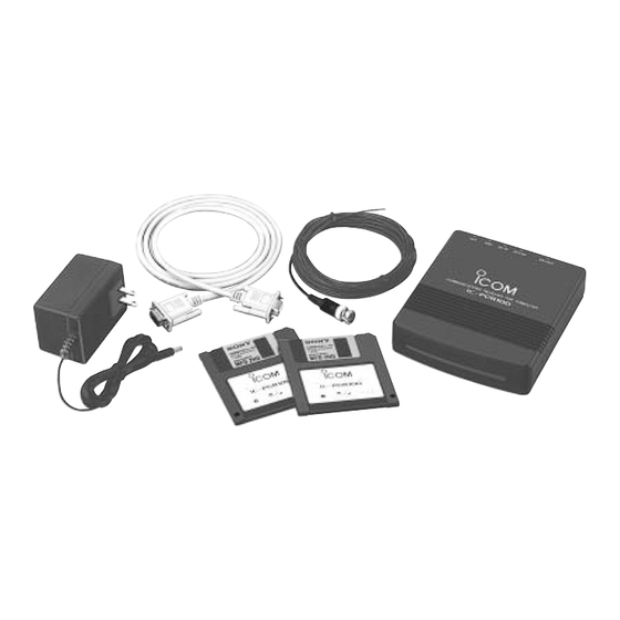
- Page 30 SECTION SECTION 7 PARTS LIST MECHANICAL PARTS AND DISASSEMBLY 7-1 CABINET PARTS 7-2 ACCESSORIES [CHASSIS] ORDER ORDER DESCRIPTION QTY. DESCRIPTION QTY. 6510015550 Connector BNC-R117 (incl. nut) 5210000040 Fuse FGB 2A [UK] only 8900007650 RS-232C cable OPC-743 MP 1 8110006550 2197 Cover MP 2 8010017560 2197 Chassis...
- Page 31 MP1 (C) MP24 (C) MP3 (C) MP7 (C) MP4 (M) SP1 (C) MP30 (C) MP10 (C) J1 (C) MP6 (M) MP7 (M) MP10 (C) MP10 (C) MP10 (C) MAIN unit MP1 (M) MP2 (M) MP3 (M) MP4 (C) MP29 (C) MP31 (C) J1 (C) MP32 (C)
- Page 32 SECTION SECTION 8 PARTS LIST SEMI-CONDUCTOR INFORMATION 8-1 TRANSISTORS AND FET’S NAME SYMBOL INSIDE VIEW NAME SYMBOL INSIDE VIEW 2SA1622-6-TL 3SK228XR 2SB1123T-TD DTA114EU 2SC4117-BL 2SC4211-6 DTA144EU 2SC4835-R 2SC5193-T1 XP1114 2SK2171-4 2SK880-Y XP1213 2SK882-GR XP4311 XP4601 3SK131-T2 8-2 DIODES NAME SYMBOL INSIDE VIEW NAME SYMBOL...
- Page 33 SECTION 9 BOARD LAYOUTS 9-1 MAIN UNIT • TOP VIEW ACHV DC IN SPO1 INSP JACK EXT SP SPO2 INSP PDTR PDTR PCTS PCTS FROM PC PTXD PTXD PRTS PRTS PRXD PRXD PDSR PDSR PDSR PDSR 9 - 1...
- Page 34 • BOTTOM VIEW 9 - 2...
-
Page 35: Block Diagram
SECTION 10 BLOCK DIAGRAM CHASSIS IC27 TC4S66F D56,D88 RF UNIT Q40 2SC4211 HVU359 FIL2 UNIT VXOV ADJUST FIL3 (2nd-IF 10.7 MHz) J1 (ANT) CR-630 BW:230 kHz –1.8 MHz CDBCA450CX24 (10.25 MHz) SFT10.7MS2-A IC31 TC4S66F Q58, Q59 (1st-IF 266.7 MHz) Q54 XP4311 D89 1SS372 2SC4211 /WF5... -
Page 36: Voltage Diagram
SECTION 11 VOLTAGE DIAGRAM 4.0 V 1SV307 ATT ON : 6.0 V ATT ON : 6.0 V ATT OFF: 4.3 V ATT OFF: 3.6 V 0.15 µH 0.18 µH 0.001 C608 L170 1SV307 1SV307 470 µH 20 p MA77 C479 10 p 0.001 4.6 V... - Page 37 4.0 V C140 EFCH266MWNT1 1SV307 C129 100 k µPC2721GV 0.18 µH 5.6 µH 5.6 µH 2SK2171 0.15 µH 0.001 1SV307 C608 C128 C130 C144 L170 1SV307 C610 C624 LR-86 33 nH 470 µH 270 p 2.2 µH LR-171 0.001 0.001 20 p MA77 22 p...
-
Page 38: Main Unit
C140 R83 4.7 k EFCH266MWNT1 C129 µPC2721GV 100 k R477 C234 1SV307 0.001 C506 C139 470 p 6.7 V C144 0.22 C238 R150 C128 C130 C610 R198 33 nH 0.01 10 k R159 C243 50 kHz: 4.1 V R197 C246 LR-171 0.001 0.001... - Page 39 SECTION 11 VOLTAGE DIAGRAM 4.0 V C140 R83 4.7 k 1SV307 EFCH266MWNT1 ATT ON : 6.0 V ATT ON : 6.0 V ATT OFF: 4.3 V ATT OFF: 3.6 V µPC2721GV C129 100 k R477 0.001 0.15 µH 0.18 µH 5.6 µH 5.6 µH 2SK2171...
- Page 40 08190 Sant Cugat Del Valles Barcelona, SPAIN Phone : ( 93 ) 589 46 82 Fax : ( 93 ) 589 04 46 A Division of Icom America Inc. E-mail : icom@lleida.com 3071 #5 Road, Unit 9, Richmond, B.C., V6X 2T4, Canada...
- Page 41 A-5548MI-S 6-9-16, Kamihigashi, Hirano-ku Osaka 547-0002, Japan © 1998 by Icom Inc.
Need help?
Do you have a question about the IC-PCR100 and is the answer not in the manual?
Questions and answers