Table of Contents
Advertisement
Quick Links
INSTRUCTION MANUAL
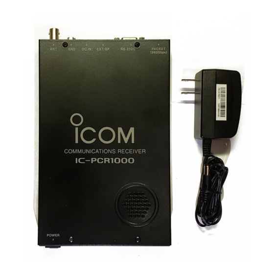
COMMUNICATIONS RECEIVER FOR COMPUTER
iPCR1000
This device complies with Part 15 of the FCC Rules. Operation is sub-
ject to the following two conditions: (1) This device may not cause
harmful interference, and (2) this device must accept any interference
received, including interference that may cause undesired operation.
Advertisement
Table of Contents

Related Manuals for Icom IC-PCR1000


Summary of Contents for Icom IC-PCR1000
- Page 1 INSTRUCTION MANUAL COMMUNICATIONS RECEIVER FOR COMPUTER iPCR1000 This device complies with Part 15 of the FCC Rules. Operation is sub- ject to the following two conditions: (1) This device may not cause harmful interference, and (2) this device must accept any interference received, including interference that may cause undesired operation.
-
Page 2: Important
NOTE of personal injury, fire or electric shock. SCANS • DIGITAL AFC CIRCUIT Versions of the IC-PCR1000 which display “CE” on the serial Icom, Icom Inc. and are registered trademarks of Icom Incorporated number seal, comply with the essential requirements of the (Japan) in the United States, United Kingdom, Germany, France, Spain, Russia 89/336/EEC directive for Electromagnetic Compatibility. -
Page 3: Precaution
AC CAUTION: outlet. This may pose a fire hazard or result in an electric Changes or modifications to this receiver, not expressly approved by Icom Inc., could void your authority to operate shock. this receiver under FCC regulations. NEVER connect other than the specified AC adapter to the... -
Page 4: Table Of Contents
I Grounding …………………………………………………………2 I AF output level selection …………………………………………3 I TNC connection ……………………………………………………4 I Software installation ………………………………………………5 I Uninstallation ………………………………………………………6 I Starting the IC-PCR1000 …………………………………………7 I Serial port setting …………………………………………………7 2 PANEL DESCRIPTION …………………………………………8–12 I Component screen…………………………………………………8 I Radio screen………………………………………………………12 I Communications receiver screen ………………………………12... -
Page 5: Installation
INSTALLATION I Hardware installation Refer to the diagram below for connections. Remove the protective sheet and attach to a specified place. USB serial adapter cable to an USB port Ground to an AC adapter to an Personal computer RS-232C port * When using the USB serial adapter cable, USB serial port can be used. -
Page 6: I Antenna Installation
R WARNING: NEVER Antennas play a very important role in receiver operation. use a gas pipe or electrical Connecting a poor quality antenna to the IC-PCR1000 will re- conduit pipe for grounding. sult in less than optimum performance. To prevent accidents involving electricity and interference Select antenna(s), such as a well-matched 50 Ω... -
Page 7: I Af Output Level Selection
Remove the 8 screws from the cover as shown below. Open the cover. e Replace the 8 screws and cover. r Connect an appropriate cable between IC-PCR1000 and - Plug for [EXT-SP] is supplied with the receiver. IC-PCR1000 to [LINE IN]... -
Page 8: I Tnc Connection
INSTALLATION I TNC connection The IC-PCR1000 can receive 9600 bps packet communica- tion (AFSK). Connect the TNC (Terminal Node Controller) as follows. IC-PCR1000 Personal computer to [PACKET]... -
Page 9: I Software Installation
INSTALLATION I Software installation ® • The “InstallShild Wizard” starts preparing the installation. When installing into a Windows XP or Windows 2000 envi- ronment, log on as the administrator. q Quit all applications when windows is running. w Insert the CD into the CD drive. e Select ‘Run’... -
Page 10: I Uninstallation
This section describes [IC-PCR1000] uninstallation. D Windows XP [Procedure] q Click <Start> and select [Control Panel]. w Click [Add or Remove Programs] and select [ICOM IC- PCR1000] and click <Change/Remove>. e [IC-PCR1000] Uninstall Wizard starts automatically. r Click <Uninstall> and follow the prompts. -
Page 11: I Starting The Ic-Pcr1000
Click the [Contents] in the [Help] menu to bring up the on- D Windows XP line help. q Before launching the program, make sure the IC-PCR1000 w Click the desired information you want to know. interface unit power is turned ON (the LED lights when power is on). -
Page 12: Panel Description
PANEL DESCRIPTION I Component screen r FREQ (frequency) indication Indicates the receive frequency and data as it is being input such as memory channel numbers, etc. See the on-line help for more information. t TS (tuning step) indicator q w e r t This is the frequency increment used when selecting a fre- quency using the [Main dial] and when searching for signals using a scan function. - Page 13 PANEL DESCRIPTION !8 SPEED (scan speed) scroll bar Sets the speed at which scans search through frequen- cies/memories for signals. Moving the knob to the right in- creases the speed; to the left decreases the speed. !9 VSC (Voice Scan Control) button Turns the voice scan control function on and off.
- Page 14 PANEL DESCRIPTION #1 MONI (Monitor) button Turns the monitor function on and off. The monitor function is used to temporarily open the squelch to listen to weak sig- nals. #2 ATT (Attenuator) button Turns the attenuator on and off. #3 AGC (Automatic Gain Control) button Turns the AGC function on and off.
- Page 15 PANEL DESCRIPTION $2 LIMIT indicator $0 $1 $4 $5 $6 Indicates when the tuning step is greater than the automatic sweep step setting. In the diagram, the tuning step is greater than the automatic sweep step setting and the tuning step (TS) and the sweep step width are not the same.
-
Page 16: I Radio Screen
PANEL DESCRIPTION I Radio screen I Communications receiver screen The radio screen shows 10 memory channel buttons and fre- quency readout, etc. like a typical stereo tuner—this provides The communications receiver screen shows S-meter (signal the simplest operation for monitoring your most-listened-to- strength) level, a large frequency readout, keypad, etc.—what stations, such as AM/FM broadcasting and TV, etc. -
Page 17: Specifications
SPECIFICATIONS • Frequency coverage (MHz) • Receive sensitivity (typical)*: U.S.A. : 0.010000–823.999999* Frequency SSB/CW 849.000001–868.999999 (MHz) (10 dB S/N) (10 dB S/N) (12 dB SINAD) (12 dB SINAD) 894.000001–1300.000000 0.5–1.799999 0.56 µV 2.5 µV Europe : 0.010000–1300.000000* — * Specifications guaranteed 0.5–1300 MHz only. 1.8–27.99999 0.28 µV 1.4 µV... -
Page 18: Specifications
SPECIFICATIONS • Selectivity : 230 kHz/–6 dB WFM/FM/AM : 50 kHz/–6 dB FM/AM : 15 kHz/–6 dB FM/AM/SSB/CW : 6 kHz/–6 dB AM/SSB/CW : 2.8* kHz/–6 dB *Software indicates 3 kHz. • IF shift range : More than ±1.2 kHz •... -
Page 19: Supplied Accesories And Options
SUPPLIED ACCESSORIES AND OPTIONS I Supplied accessories I Options • AH-7000 SUPER WIDEBAND OMNIDIRECTIONAL ANTENNA Frequency coverage Receive 25–1300 MHz Transmit 50, 144, 430, 900, 1200 MHz bands Type of antenna : Discone Weight : 1 kg • UT-106 DSP UNIT Provide AF DSP functions such as noise reduction and auto notch. - Page 20 A-5456H-1EX-e Printed in Japan 1-1-32 Kamiminami, Hirano-ku, Osaka 547-0003 Japan © 1997–2003 Icom Inc.
Need help?
Do you have a question about the IC-PCR1000 and is the answer not in the manual?
Questions and answers