Table of Contents
Advertisement
Quick Links
Oct. 2008
SERVICE MANUAL
ADDENDUM
CONTENTS
REPLACEMENT PAGES. . . . . . . . . . . . . . . . . . . . . . . . . . . . . . . –
PARTS LIST. . . . . . . . . . . . . . . . . . . . . . . . . . . . . . . . . . . . . . . . . 1
BOARD LAYOUTS. . . . . . . . . . . . . . . . . . . . . . . . . . . . . . . . . . . . 9
VOLTAGE DIAGRAM . . . . . . . . . . . . . . . . . . . . . . . . . . . . . . . . . .11
Advertisement
Table of Contents

Related Manuals for Icom IC-A110EURO


Summary of Contents for Icom IC-A110EURO
- Page 1 Oct. 2008 SERVICE MANUAL ADDENDUM CONTENTS REPLACEMENT PAGES....... – PARTS LIST......... 1 BOARD LAYOUTS.
- Page 2 (REPLACEMENT PAGE) Oct. 2008 SECTION 4 ADJUSTMENT PROCEDURES 4-1 PREPARATION Some versions may need the optional CS-A110 and OPC-478, OPC-592 for setting the CLONING SOFTWARE CLONING CABLE adjustment frequency. All adjustments must be performed on the [Wide] mode. ■REQUIRED TEST EQUIPMENT EQUIPMENT GRADE AND RANGE EQUIPMENT...
- Page 3 (REPLACEMENT PAGE) Oct. 2008 4-2 PLL ADJUSTMENT ADJUSTMENT MEASUREMENT POINT ADJUSTMENT ADJUSTMENT CONDITION VALUE UNIT LOCATION UNIT ADJUST Operating frequency : MAIN Connect a digital 13.5 V MAIN R392 DRAIN 118.000 MHz multi-meter to drain VOLTAGE Receiving terminal of Q51. 1) Unsolder CP5.
- Page 4 (REPLACEMENT PAGE) Oct. 2008 pin 2 ( MICE) Audio generator pin 4 ( GND) pin 3 ( MIC) pin 5 ( PTT) J6, pin 3 DC power supply Audio input point 13.75 V/10 A R336 Head set modulation R222 adjustment Idd adjustment Vdd check point TUNE voltage adjustment...
- Page 5 Oct. 2008 PARTS LIST [FRONT UNIT] [FRONT UNIT] ORDER ORDER DESCRIPTION DESCRIPTION 4030006860 S.CER C1608 JB 1H 102K-T 1140008780 S.IC HD6433823A19D Except [A110EURO] 4030006860 S.CER C1608 JB 1H 102K-T 1140009830 S.IC HD6433823A80D [A110EURO] 4030011600 S.CER C1608 JB 1E 104K-T 1110005771 S.IC S-80942CNMC-G9CT2G 4030006860 S.CER C1608 JB 1H 102K-T 1130007111 S.IC...
- Page 6 Oct. 2008 [MAIN UNIT] [MAIN UNIT] ORDER ORDER DESCRIPTION DESCRIPTION LOCATION LOCATION 1590000430 S.TRA DTC144EUA T106 33.2/98.8 1130008831 S.IC TB31207AFNG(EL) 1 88/26.6 1510000771 S.TRA 2SA1586-GR(TE85L,F) 85.4/69.5 1110003670 S.IC BA3308F-E2 102.7/22.9 1530002851 S.TRA 2SC4116-BL(TE85R,F) 91.5/72.4 1110002751 S.IC TA75S01F(TE85R,F) 109.7/21 Q100 1590003820 S.FET FW261-TL-E 16.7/111.1 1130004201 S.IC TC4S66F(TE85R,F)
- Page 7 Oct. 2008 [MAIN UNIT] [MAIN UNIT] ORDER ORDER DESCRIPTION DESCRIPTION LOCATION LOCATION 7030003280 S.RES ERJ3GEYJ 470 V (47) 118.6/66.5 6050010831 S.XTA CR-657A TCXO GS41130 12.8 MHz 7030003720 S.RES ERJ3GEYJ 224 V (220K) 112.3/62.1 [GEN] 89.2/24.9 7030003720 S.RES ERJ3GEYJ 224 V (220K) 108.9/62.1 6050010831 S.XTA CR-657A TCXO GS41130 12.8 MHz 7030003720 S.RES ERJ3GEYJ 224 V (220K)
- Page 8 Oct. 2008 [MAIN UNIT] [MAIN UNIT] ORDER ORDER DESCRIPTION DESCRIPTION LOCATION LOCATION R374 7030003680 S.RES ERJ3GEYJ 104 V (100K) 112.3/31.5 R148 7030003600 S.RES ERJ3GEYJ 223 V (22K) 87.6/84.2 R375 7030003530 S.RES ERJ3GEYJ 562 V (5.6K) 113.2/27.5 R149 7030003520 S.RES ERJ3GEYJ 472 V (4.7K) 84.3/79 R376 7030003770 S.RES ERJ3GEYJ 564 V (560K)
- Page 9 Oct. 2008 [MAIN UNIT] [MAIN UNIT] ORDER ORDER DESCRIPTION DESCRIPTION LOCATION LOCATION 4030011180 S.CER GRM31M2C2H220JV01L R467 7030003800 S.RES ERJ3GEYJ 105 V (1M) 43.6/63.7 (GRM42-6 CH) 97.7/102.6 R468 7030006120 S.RES ERJ1WYJ4R7U (4.7)0 50.3/105.4 4030011020 S.CER GRM31M4C2H1R0CY21L R469 7030006120 S.RES ERJ1WYJ4R7U (4.7)0 51.3/105.4 (GRM42-6 CK) 96.1/96.1...
- Page 10 Oct. 2008 [MAIN UNIT] [MAIN UNIT] ORDER ORDER DESCRIPTION DESCRIPTION LOCATION LOCATION C299 4030006890 S.CER C1608 JF 1H 103Z-T 25.3/46.6 C126 4030011600 S.CER C1608 JB 1E 104K-T 51.2/37 C300 4030011600 S.CER C1608 JB 1E 104K-T 28.8/46 C127 4030006900 S.CER C1608 JB 1H 103K-T 56.5/44.8 C301 4510008580 S.ELE EEE0JA470SR...
- Page 11 Oct. 2008 [MAIN UNIT] [MAIN UNIT] ORDER ORDER DESCRIPTION DESCRIPTION LOCATION LOCATION C538 4030009650 S.CER C1608 CH 1H 240J-T [EUR] C422 4030007070 S.CER C1608 CH 1H 330J-T 110/39.4 4030009650 S.CER C1608 CH 1H 240J-T [EUR-1] C423 4030006970 S.CER C1608 CH 1H 060D-T 110.8/37.2 C539 4030007010 S.CER C1608 CH 1H 100D-T...
- Page 12 Oct. 2008 [MAIN UNIT] ORDER DESCRIPTION LOCATION 9040901901 TUB 0.7 L=12MM 6910010220 BEA HF70BB3.5X5X1.3 [EUR] 6910010220 BEA HF70BB3.5X5X1.3 [EUR-1] 9025608001 TUB 1 L=7MM M.=Mounted side (T: Mounted on the Top side, B: Mounted on the Bottom side) S.=Surface mount...
- Page 13 Oct. 2008 SECTION 9 BOARD LAYOUTS (Jun. 2008) • MAIN UNIT (A110/A110EURO) (TOP VIEW) • FRONT UNIT (A110) • FRONT UNIT (A110EURO) (TOP VIEW) (TOP VIEW) B5531E MP13 C554 R473 R336 C504 C389 C502 C503 C388 C217 C501 C103 C366 C573 C220 C513...
- Page 14 Oct. 2008 • MAIN UNIT (A110/A110EURO) • FRONT UNIT (A110EURO) • FRONT UNIT (A110) (BOTTOM VIEW) (BOTTOM VIEW) (BOTTOM VIEW) R418 R462 R420 R419 R463 C331 R417 R441 C518 C549 C249 C562 C563 Q101 C564 R433 C569 C316 C570 C571 R323 R153 C410...
- Page 15 Oct. 2008 SECTION 11. VOLTAGE DIAGRAM • MAIN UNIT 1SV307 R447 C333 0.01 1.2K R377 617DB LS-527 LS-527 0.5P IC52 C358 C342 C165 1SV271 C362 C255 3SK293 0.75P 0.001 0.001 LA-244 LA-244 0.001 LA-263 LA-253 LA-243 0.01 0.001 #617DB 220K T:0V SPM5001 DTB123EK...
- Page 16 Jun. 2008 SERVICE MANUAL ADDENDUM CONTENTS PARTS LIST......... 1 BOARD LAYOUTS.
- Page 17 Jun. 2008 PARTS LIST [FRONT UNIT] [FRONT UNIT] ORDER ORDER DESCRIPTION DESCRIPTION 4030011600 S.CER C1608 JB 1E 104K-T 1140008780 S.IC HD6433823A19D 4030006860 S.CER C1608 JB 1H 102K-T except[A110EURO] 4030006860 S.CER C1608 JB 1H 102K-T 1140009830 S.IC HD6433823A80D [A110EURO] 4030011600 S.CER C1608 JB 1E 104K-T 1110005771 S.IC S-80942CNMC-G9CT2G 4030006860 S.CER C1608 JB 1H 102K-T...
- Page 18 Jun. 2008 [MAIN UNIT] [MAIN UNIT] ORDER ORDER DESCRIPTION DESCRIPTION LOCATION LOCATION 1720000781 S.VCP HVU350BTRF-E 110.6/65 1130008831 S.IC TB31207AFNG (EL) 88/26.6 1720000781 S.VCP HVU350BTRF-E 107.2/65.6 1110003670 S.IC BA3308F-E2 102.7/22.9 1790000620 S.DIO MA77 (TX) 99.5/51.7 1110002751 S.IC TA75S01F (TE85R,F) 109.7/21 1790000620 S.DIO MA77 (TX) 98.7/54.4 1130004201 S.IC TC4S66F (TE85R,F)
- Page 19 Jun. 2008 [MAIN UNIT] [MAIN UNIT] ORDER ORDER DESCRIPTION DESCRIPTION LOCATION LOCATION R127 7030003560 S.RES ERJ3GEYJ 103 V (10 k) 70.1/17.5 6190001690 S.COL ZBFS5105-PT-01 42.7/46.2 R128 7030003560 S.RES ERJ3GEYJ 103 V (10 k) 65.3/18.9 6190001690 S.COL ZBFS5105-PT-01 22.2/44.5 R131 7030003440 S.RES ERJ3GEYJ 102 V (1 k) 53/37.6 6190001690 S.COL ZBFS5105-PT-01 55.2/16.8...
- Page 20 Jun. 2008 [MAIN UNIT] [MAIN UNIT] ORDER ORDER DESCRIPTION DESCRIPTION LOCATION LOCATION R486 7030003420 S.RES ERJ3GEYJ 681 V (680) 46.7/45.4 R379 7030003680 S.RES ERJ3GEYJ 104 V (100 k) 58.3/35.7 R487 7030003560 S.RES ERJ3GEYJ 103 V (10 k) 45.8/39.5 R380 7030006060 S.RES ERJ12YJ100U (10) 38/81.7 R488 7030003560 S.RES ERJ3GEYJ 103 V (10 k)
- Page 21 Jun. 2008 [MAIN UNIT] [MAIN UNIT] ORDER ORDER DESCRIPTION DESCRIPTION LOCATION LOCATION C300 4030011600 S.CER C1608 JB 1E 104K-T 28.8/46 C110 4030012600 S.CER C2012 JB 1A 105M-T 106.4/11.9 C301 4510008580 S.ELE EEE0JA470SR 18.8/49.4 C112 4550006220 S.TAN TEESVA 0J 156M8R 109.4/26.5 C308 4030006900 S.CER C1608 JB 1H 103K-T 91/12.4...
- Page 22 Jun. 2008 [MAIN UNIT] [MAIN UNIT] ORDER ORDER DESCRIPTION DESCRIPTION LOCATION LOCATION C571 4030005030 S.CER C2012 CH 1H 221J-T C447 4030012600 S.CER C2012 JB 1A 105M-T 8.8/18.7 [A110EURO] only B 42.8/94.6 C448 4510008500 S.ELE EEE1CA101WP 10.7/43 C572 4030007170 S.CER C1608 CH 1H 221J-T C449 4030006900 S.CER C1608 JB 1H 103K-T 12.9/38.8...
- Page 23 Jun. 2008 SECTION 9 BOARD LAYOUTS (Jun. 2008) • MAIN UNIT (A110/A110EURO) (TOP VIEW) • FRONT UNIT (A110) • FRONT UNIT (A110EURO) (TOP VIEW) (TOP VIEW) B5531D MP13 C554 R473 R336 C504 C389 C502 C503 C388 C217 C501 C103 C366 C573 C220 C513...
- Page 24 • MAIN UNIT (A110/A110EURO) • FRONT UNIT (A110EURO) • FRONT UNIT (A110) (BOTTOM VIEW) (BOTTOM VIEW) (BOTTOM VIEW) R418 R462 R420 R419 R463 C331 R417 R441 C518 C549 C249 C562 C563 Q101 C564 R433 C569 C316 C570 C571 R323 R153 C410 R152 C139...
- Page 25 Jun. 2008 SECTION 11. VOLTAGE DIAGRAM 1SV307 R447 C333 R377 0.01 1.2K 617DB LS-527 LS-527 0.5P IC52 C358 C342 C165 1SV271 C362 C255 3SK293 0.75P 0.001 0.001 LA-244 LA-244 0.001 LA-263 LA-253 LA-243 0.01 0.001 #617DB 220K T:0V SPM5001 1SV307 DTB123EK C330 R:3.77V...
- Page 26 Sep. 2006 SERVICE MANUAL ADDENDUM CONTENTS PARTS LIST......... 1 BOARD LAYOUTS.
- Page 27 PARTS LIST [FRONT UNIT] [FRONT UNIT] ORDER ORDER DESCRIPTION DESCRIPTION 4030011600 S.CER C1608 JB 1E 104K-T 1140008780 S.IC HD6433823A19D except[EUR], [EUR-1] 4030006860 S.CER C1608 JB 1H 102K-T 1140009830 S.IC HD6433823A80D [EUR], [EUR-1] 4030011600 S.CER C1608 JB 1E 104K-T 1110005771 S.IC S-80942CNMC-G9CT2G 4550006480 S.TAN TEESVA 1C 475M8R 1130007111 S.IC...
- Page 28 [MAIN UNIT] [MAIN UNIT] ORDER ORDER DESCRIPTION DESCRIPTION LOCATION LOCATION 1790001670 S.DIO RB706F-40T106 88.3/90.4 1130008831 S.IC TB31207AFNG (EL) 88/26.6 1720000781 S.VCP HVU350BTRF-E 133.5/65.7 1110003670 S.IC BA3308F-E2 102.7/22.9 1720000781 S.VCP HVU350BTRF-E 110.6/65 1110002751 S.IC TA75S01F 109.7/21 1720000781 S.VCP HVU350BTRF-E 107.2/65.6 1130004201 S.IC TC4S66F 60.1/37.4 1790000620 S.DIO MA77 (TX)
- Page 29 [MAIN UNIT] [MAIN UNIT] ORDER ORDER DESCRIPTION DESCRIPTION LOCATION LOCATION R123 7030003630 S.RES ERJ3GEYJ 393 V (39 k) 112.7/9.3 6200009120 S.COL 0.20-0.7-4TR 8.8N 49.9/94.6 R124 7030003630 S.RES ERJ3GEYJ 393 V (39 k) 110.6/6.5 6200008270 S.COL 0.26-1.0-5TL 17N 50.5/98.8 R126 7030003560 S.RES ERJ3GEYJ 103 V (10 k) 74.8/17.8 6110001520 COL LA-232...
- Page 30 [MAIN UNIT] [MAIN UNIT] ORDER ORDER DESCRIPTION DESCRIPTION LOCATION LOCATION R469 7030000100 S.RES MCR10EZHJ 4R7 (4.7) R370 7030003560 S.RES ERJ3GEYJ 103 V (10 k) 130.4/10.4 [GEN-1], [USA], [USA-1] B 51.3/105.4 R371 7030003560 S.RES ERJ3GEYJ 103 V (10 k) 122.3/13 R470 7030003600 S.RES ERJ3GEYJ 223 V (22 k) 15.8/23.7 R372...
- Page 31 [MAIN UNIT] [MAIN UNIT] ORDER ORDER DESCRIPTION DESCRIPTION LOCATION LOCATION C260 4030006860 S.CER C1608 JB 1H 102K-T 65.1/30 4030006860 S.CER C1608 JB 1H 102K-T 93.1/62.1 C261 4030008880 S.CER C1608 JB 1H 223K-T 61.3/34.8 4030007030 S.CER C1608 CH 1H 150J-T 88/58.2 C262 4030011340 S.CER C1608 CH 1H 471J-T 58.3/33.4...
- Page 32 [MAIN UNIT] [MAIN UNIT] ORDER ORDER DESCRIPTION DESCRIPTION LOCATION LOCATION C546 4030007000 S.CER C1608 CH 1H 090D-T 81.7/36.2 C407 4030009910 S.CER C1608 CH 1H 040B-T 111.5/67.4 C547 4030009650 S.CER C1608 CH 1H 240J-T 79.3/36.6 C409 4030006860 S.CER C1608 JB 1H 102K-T 93.4/46.9 C548 4030006860 S.CER C1608 JB 1H 102K-T...
- Page 33 BOARD LAYOUTS...
- Page 34 S P E S P E...
- Page 35 VOLTAGE DIAGRAM 1SV307 C333 R447 0.01 1.2K R377 617DB LS-527 LS-527 0.5P IC52 C358 C342 C165 1SV271 C362 C255 3SK293 0.75P 0.001 0.001 LA-244 LA-244 0.001 LA-263 LA-253 LA-243 0.01 0.001 #617DB T:0V SPM5001 220K DTB123EK 1SV307 R:3.77V C330 R438 R439 R499 R500...
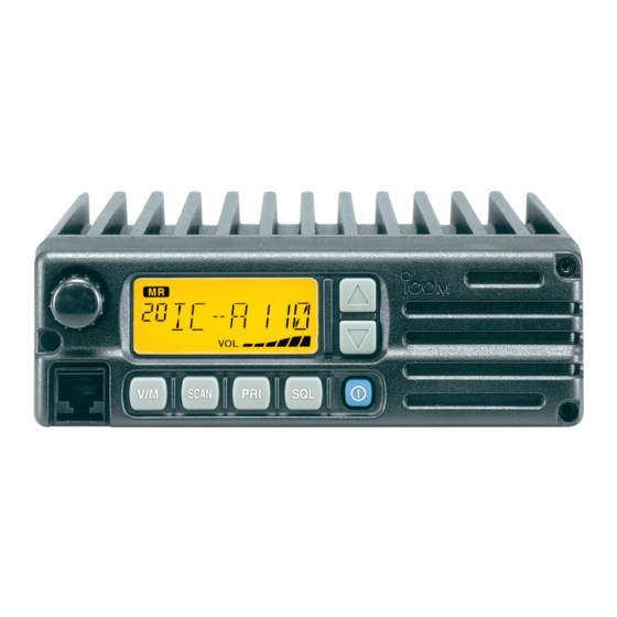
- Page 36 SERVICE MANUAL VHF AIR BAND TRANSCEIVER iA110 iA110EURO...
- Page 37 This service manual describes the latest service information NEVER connect the transceiver to an AC outlet or to a DC for the IC-A110, IC-A110EURO VHF AIR BAND TRANS- power supply that uses more than 16 V. This will ruin the transceiver.
-
Page 38: Table Of Contents
FRONT UNIT (IC-A110) ........................... 8 - 1 8 - 2 MAIN UNIT (IC-A110) ..........................8 - 3 8 - 3 FRONT UNIT (IC-A110EURO)........................8 - 5 8 - 4 MAIN UNIT (IC-A110EURO) ........................8 - 7 SECTION 9 BLOCK DIAGRAM SECTION 10 VOLTAGE DIAGRAM 10 - 1 FRONT UNIT ............................10 - 1... -
Page 39: Specifications
SECTION 1 SPECIFICATIONS 1-1 IC-A110 SPECIFICATIONS ‘ GENERAL • Frequency coverage : 118.000–136.975 MHz • ], [CHN] 25 kHz/8.33 kHz [USA], [USA-1] • • Number of memory channels : 99 channels : SO-239 (50 Ω) • Antenna connector • Power supply requirement : 13.75 V DC or 27.5 V DC (negative ground) •... -
Page 40: Ic-A110Euro
1-2 IC-A110EURO SPECIFICATIONS ‘ ‘ RECEIVER • Receive system : Double conversion super- ‘ ‘ GENERAL heterodyne system • Frequency coverage : 118.000–136.975 MHz • Intermediate frequencies : 1st 38.85 MHz • Channel spacing : 25 kHz/8.33 kHz 450 kHz •... -
Page 41: Inside Views
SECTION 2 INSIDE VIEWS ¡MAIN UNIT (IC-A110) <TOP VIEW> Power complifier (Q51: MRF137) Low-pass filter Antenna switching circuit APC amplifier (Q11: 2SC4081) Crystal band pass filter (FI2: FL-307 [USA/-1] only) Crystal band pass filter VCO circuit (FI1: FL-306) Ceramic band pass filter TCXO (FI3: CFWM450D) (X1: CR-657A) -
Page 42: Ic-A110Euro
¡MAIN UNIT (IC-A110EURO) <TOP VIEW> Power complifier (Q51: MRF137) Low-pass filter Antenna switching circuit APC amplifier (Q11: 2SC4081) Crystal band pass filter (FI2: FL-307) Crystal band pass filter VCO circuit (FI1: FL-306) Ceramic band pass filter TCXO (FI3: CFWM450D) (X1: CR-658A) -
Page 43: Circuit Description
SECTION 3 CIRCUIT DESCRIPTION 3-1 RECEIVER CIRCUITS 3-1-3 1ST MIXER AND 1ST IF CIRCUITS (MAIN UNIT) 3-1-1 ANTENNA SWITCHING CIRCUIT (MAIN UNIT) The 1st mixer circuit converts the received signal into a fixed The antenna switching circuit functions as a low-pass filter frequency of the 1st IF signal with a PLL output frequency. - Page 44 3-1-5 AM DETECTOR CIRCUIT (MAIN UNIT) 3-1-7 SQUELCH CIRCUIT The AM detector circuit converts the 2nd IF signal into AF (MAIN AND FRONT UNITS) signals. The squelch circuit cuts out AF signals when receiving no modulated signal. When no voice modulation is included in The amplified 2nd IF signal from the 2nd IF amplifier (Q6) is the signal, the squelch circuit cuts out the AF signal by com- applied to the AM detector circuit (Q7).
-
Page 45: Transmitter Circuits
3-2 TRANSMITTER CIRCUITS 3-2-3 DRIVE/POWER AMPLIFIER CIRCUITS (MAIN UNIT) 3-2-1 MICROPHONE AMPLIFIER CIRCUIT The amplifier circuit amplifies the VCO oscillating signal to (MAIN UNIT) the output power level. The microphone amplifier circuit amplifies audio signals from the microphone, within +6 dB/octave pre-emphasis The signal from the buffer amplifiers (Q14, Q15) is passed characteristics (300 Hz–3 kHz), to a level needed for the through the TX/RX switch (D11), and is amplified at the pre-... -
Page 46: Pll Circuits
3-3 PLL CIRCUIT 3-3-3 RX LOOP (MAIN UNIT) The generated signal at the RX-VCO (Q59, D65) enters the 3-3-1 GENERAL (MAIN UNIT) PLL IC (IC2, pin 8), and is divided at the programmable A PLL circuit provides stable oscillation of the transmit fre- divider section. -
Page 47: Power Supply Circuits
3-5 PORT ALLOCATIONS 3-4 POWER SUPPLY CIRCUITS VOLTAGE LINES (MAIN UNIT) 3-5-1 OUTPUT EXPANDER IC (FRONT UNIT: IC5) Port LINE DESCRIPTION Description number name The voltage from the external DC power con- nector which is controlled by the power switch Outputs backlight control signals. - Page 48 3-5-2 CPU (FRONT UNIT; IC1) Port Port Description Description number name number name 1, 2, 3, Input port for the microphone hanger Input ports for the key matrix. 5, 8, 12 HANG detection signal. Low: Microphone on hook. RESET Input port for the CPU reset signal. Input port for the PTT switch.
-
Page 49: Adjustment Procedures
SECTION 4 ADJUSTMENT PROCEDURES 4-1 PREPARATION • Some versions may need the optional CS-A110 and OPC-478, OPC-592 for setting the CLONING SOFTWARE CLONING CABLE adjustment frequency. • All adjustments must be performed on the [Wide] mode. ■REQUIRED TEST EQUIPMENT EQUIPMENT GRADE AND RANGE EQUIPMENT GRADE AND RANGE... - Page 50 CONNECTION Modulation Attenuator Power supply analyzer 40 dB or 50 dB DC 13.75 V, 10 A RF power meter 50 Ω, 1–50 W Standard signal generator (SSG) 0.1–300 MHz Distortion –127 to –17 dBm (0.1 µV to 32 mV) meter CAUTION! AC millivoltmeter DO NOT transmit...
-
Page 51: Pll Adjustments
4-2 PLL ADJUSTMENT ADJUSTMENT MEASUREMENT POINT ADJUSTMENT ADJUSTMENT CONDITION VALUE UNIT LOCATION UNIT ADJUST • Operating frequency : MAIN Connect a digital 13.5 V MAIN R392 VOLTAGE 118.000 MHz multi-meter to drain • Receiving terminal of Q51. PLL LOCK • Operating frequency : MAIN Connect a digital 0.5 V... - Page 52 pin 2 ( MICE) Audio generator pin 4 ( GND) pin 3 ( MIC) pin 5 ( PTT) J6, pin 3 Audio input point DC power supply 13.75 V/10 A R336 Head set modulation adjustment Vdd voltage check point TUNE voltage adjustment TUNE voltage check point R150 Output power adjustment...
-
Page 53: Receiver Adjustment
4-4 RECEIVER ADJUSTMENT “SQUELCH ADJUSTMENT” must be performed at “SQUELCH ADJUSTMENT MODE”. ADJUSTMENT MEASUREMENT POINT ADJUSTMENT ADJUSTMENT CONDITION VALUE UNIT LOCATION UNIT ADJUST • Operating frequency : Rear Connect an AC milli- Maximum AF output MAIN L9, L10, SENSITIVITY 118.000 MHz panel voltmeter and dis- level... - Page 54 DC power supply 13.75 V/10 A RX sensitivity adjustment 4 - 6...
-
Page 55: Parts List
SECTION 5 PARTS LIST [FRONT UNIT] [FRONT UNIT] ORDER ORDER DESCRIPTION DESCRIPTION 7030003580 S.RESISTOR ERJ3GEYJ 153 V (15 kΩ) 1140008780 S.IC HD6433823A19D 7030003610 S.RESISTOR ERJ3GEYJ 273 V (27 kΩ) 1140009830 S.IC HD6433823A80D 1130009110 S.IC S-80942ANMP-DD6-T2 7030003580 S.RESISTOR ERJ3GEYJ 153 V (15 kΩ) 1130007110 S.IC TC7W04FU (TE12L) 1190001600 S.IC... - Page 56 [MAIN UNIT] [MAIN UNIT] ORDER ORDER DESCRIPTION DESCRIPTION 1130008830 S.IC TB31207AFN (EL) 1590000430 S.TRANSISTOR DTC144EUA T106 1110003670 S.IC BA3308F-T1 1590000430 S.TRANSISTOR DTC144EUA T106 1110002750 S.IC TA75S01F (TE85R) 1510000770 S.TRANSISTOR 2SA1586-GR (TE85R) 1130004200 S.IC TC4S66F (TE85R) 1530002850 S.TRANSISTOR 2SC4116-BL (TE85R) 1180000800 S.IC S-81350HG-KD-T1 Q100 1590002870 S.FET...
- Page 57 [MAIN UNIT] [MAIN UNIT] ORDER ORDER DESCRIPTION DESCRIPTION 6200008270 S.COIL 0.26-1.0-5TL 17N 7030003460 S.RESISTOR ERJ3GEYJ 152 V (1.5 kΩ) 6140000670 COIL LR-89 7030003480 S.RESISTOR ERJ3GEYJ 222 V (2.2 kΩ) 6200004480 S.COIL MLF1608D R82K-T 7030003440 S.RESISTOR ERJ3GEYJ 102 V (1 kΩ) 6200009080 S.COIL MC152-E558CN-100025=P3 7030003500 S.RESISTOR...
- Page 58 [MAIN UNIT] [MAIN UNIT] ORDER ORDER DESCRIPTION DESCRIPTION B only R231 7030003520 S.RESISTOR ERJ3GEYJ 472 V (4.7 kΩ) R400 7030003440 S.RESISTOR ERJ3GEYJ 102 V (1 kΩ) R232 7030003520 S.RESISTOR ERJ3GEYJ 472 V (4.7 kΩ) R401 7030003480 S.RESISTOR ERJ3GEYJ 222 V (2.2 kΩ) R233 7030003520 S.RESISTOR ERJ3GEYJ 472 V (4.7 kΩ)
- Page 59 [MAIN UNIT] [MAIN UNIT] ORDER ORDER DESCRIPTION DESCRIPTION 4030011210 S.CERAMIC GRM42-6 CH 330J 500PT C103 4030007100 S.CERAMIC C1608 CH 1H 560J-T-A 4030011070 S.CERAMIC GRM42-6 CH 050C 500PT C110 4030012600 S.CERAMIC C2012 JB 1A 105M-T-A 4030011230 S.CERAMIC GRM42-6 CH 390J 500PT C112 4550006220 S.TANTALUM TEMSVA 0J 156M-8L...
- Page 60 [MAIN UNIT] [MAIN UNIT] ORDER ORDER DESCRIPTION DESCRIPTION C261 4030008880 S.CERAMIC C1608 JB 1C 223K-T-A C396 4030012610 S.CERAMIC C2012 JB 1C 474K-T-A C262 4030011340 S.CERAMIC C1608 CH 1H 471J-T-A C397 4030012610 S.CERAMIC C2012 JB 1C 474K-T-A C263 4030012660 S.CERAMIC C1608 JB 1C 683K-T-N C398 4030009000 S.CERAMIC C2012 JB 1C 224K-T-A...
- Page 61 [MAIN UNIT] [MAIN UNIT] ORDER ORDER DESCRIPTION DESCRIPTION C523 4030006870 S.CERAMIC C1608 JB 1H 222K-T-A 7030003860 S.JUMPER ERJ3GE JPW V C524 4030008550 S.CERAMIC C2012 JF 1H 473Z-T-A 7030003860 S.JUMPER ERJ3GE JPW V C525 4030006860 S.CERAMIC C1608 JB 1H 102K-T-A 7030003860 S.JUMPER ERJ3GE JPW V C529 4030008920 S.CERAMIC...
-
Page 62: Mechanical Parts And Dissasembly
SECTION 6 MECHANICAL PARTS AND DISSASEMBLY [CHASSIS PARTS] [MAIN UNIT] REF. NO ORDER NO. DESCRIPTION QTY. REF. NO ORDER NO. DESCRIPTION QTY. 6510004880 Connector MR-DS-E 01 6450000140 Connector HSJ0807-01-010 8010017872 2270 chassis-2 42-324 8900009210 Cable OPC-905 8810008660 Screw PH BT M3 X 8 NI-ZU 8810008490 Setscrew H M2.6 X 8 NI 8510011660... - Page 63 OPPOSITE DIRECTION TO THE MAIN UNIT MP4 (C) MP4 (M) J1 (C) MP12 (C) W1 (M) MP5 (M) MP9 (M) MP3 (C) FRONT UNIT MP6 (M) MP10 (F) MP14 (F) MP2 (M) MP2 (C) MP6 (C) MP10 (F) MP2 (C) MP8 (M) EP2 (F) MP15 (F)
-
Page 64: Semi-Conductor Information
SECTION 7 SEMI-CONDUCTOR INFORMATION • • TRANSISTORS AND FET’S DIODES 2SA1471R 2SA1586 GR 2SA1622 6 TL 2SB1132 T100 R 2SB798 T2 DK 1SS193 1SS352 1SV271 1SV307 DA204 U T107 (Symbol: SG) (Symbol: M6) (Symbol: BART) (Symbol: DK) (Symbol: F3) (Symbol: C1) (Symbol: TG) (Symbol: TX) (Symbol: K) -
Page 65: Front Unit (Ic-A110)
SECTION 8 BOARD LAYOUTS 8-1 FRONT UNIT (IC-A110) The combination of this page and the next page show the unit layout in the same configuration as the actual P.C.Board. ¡TOP VIEW HANG MICE CLON 8 - 1... - Page 66 ¡BOTTOM VIEW RMUT AFMUT SMUT BEEP from/to MAIN FISW unit J5 TMUT UNLK PSWC PLSTB CPU5V MICE PDET PTTS SQLI 8 - 2...
-
Page 67: Main Unit (Ic-A110)
8-2 MAIN UNIT (IC-A110) EXT SP The combination of this page and the next page show the unit layout in the same configuration as the actual ¡TOP VIEW P.C.Board. from/to FRONT unit J1 8 - 3... - Page 68 ¡BOTTOM VIEW 8 - 4...
-
Page 69: Front Unit (Ic-A110Euro)
8-3 FRONT UNIT (IC-A110EURO) The combination of this page and the next page show the unit layout in the same configuration as the actual P.C.Board. ¡TOP VIEW HANG MICE CLON 8 - 5... - Page 70 ¡BOTTOM VIEW RMUT AFMUT SMUT BEEP from/to MAIN FISW unit J5 TMUT UNLK PSWC PLSTB CPU5V MICE PDET PTTS SQLI 8 - 6...
-
Page 71: Main Unit (Ic-A110Euro)
8-4 MAIN UNIT (IC-A110EURO) EXT SP The combination of this page and the next page show the unit layout in the same configuration as the actual ¡TOP VIEW P.C.Board. MP13 from/to FRONT unit J1 8 - 7... - Page 72 ¡BOTTOM VIEW MP18 MP16 8 - 8...
-
Page 73: Block Diagram
SECTION 9 BLOCK DIAGRAM [ ANT ] 1st MIX D51-D52 1st IF=38.85 MHz 2nd IF=450 kHz 1SV271×2 D50: 1SV271 Q4-Q5 D44: MA8051 D7,D8 D6,D37 D1-D3 Q3: 2SC4215 3SK184 3SK184 2SC4211 2SC4215 2SC4215×2 CFWM450D IC40: TA31136FN 1SV307 FL-306 1SV307 HVU350B×2 HVU350B×2 1SV271 MA4PH224×3 2nd IF... - Page 74 SECTION 10 VOLTAGE DIAGRAM 10-1 FRONT UNIT Dimmer OFF : 0V Light : 7.8V Dark : 6.1V HLC7453-012400 Note A : [A110EURO] Dimmer OFF : 0V Light : 7.8V C : [A110] Dark : 6.1V DTC114EU CL-170Y-CD CL-170Y-CD CL-170Y-CD DTA143ZU DTA143ZU DTC114EU CL-170Y-CD...
-
Page 75: Main Unit
10-2 MAIN UNIT C333 R447 R448 FL-306 Note 1SV307 0.01 1.2k 1SV307 R377 TX: 0 V 0.5p 0.001 RX: 5.6 V TX: 0.39 V TX: 0 V A : [A110EURO] C255 RX: 2.08 V RX: 1.7 V B : [USA/-1], [A110EURO] 0.001 C358 RF AGC... - Page 76 CHASSIS MOD V (W36) MOD V (ANT) TX: 0 V RX: 5.6 V TX: 0.39 V TX: 0 V HK-08S070- HK-08S070- HK-08S070- 1310 1310 1310 ZBFS5101-PT RX: 2.08 V RX: 1.7 V C358 C342 C165 C362 RF AGC 0.75p 1SV271 0.001 LA-244 LA-244...
- Page 77 10-2 MAIN UNIT CHASSIS MOD V (W36) MOD V C333 R447 R448 FL-306 1SV307 0.01 1.2k 1SV307 (ANT) Note R377 TX: 0 V 0.5p 0.001 RX: 5.6 V TX: 0 V HK-08S070- HK-08S070- HK-08S070- A : [A110EURO] TX: 0.39 V C255 RX: 1.7 V 1310...
- Page 78 Phone : +34 (93) 590 26 70 Fax : +34 (93) 589 04 46 : http://www.icomspain.com Glenwood Centre #150-6165 E-mail : icom@icomspain.com Highway 17 Delta, B.C., V4K 5B8, Canada Phone : +1 (604) 952-4266 Fax : +1 (604) 952-0090 : http://www.icomcanada.com E-mail : info@icomcanada.com...
- Page 79 S-13608HZ-C1-2 1-1-32, Kamiminami, Hirano-ku, Osaka 547-0003, Japan c 2001 Icom Inc.
Need help?
Do you have a question about the IC-A110EURO and is the answer not in the manual?
Questions and answers